1
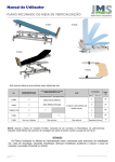
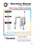
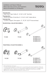
community bed
user manual
bringing you the world in health
Introduction
Congratulations on your purchase of a Novis Community bed. This modular patient support
product is designed especially for home and facility nursing care. It combines ease of
handling with all the functionality necessary for most aspects of patient care.
If you experience difficulties during the assembly or use of this product please ring Novis
Healthcare on 1300 738 885 Australia wide for the cost of a local call.
Novis Healthcare reserves the right to alter any product specification without prior notice.
Novis Healthcare accepts no liability for any use, change or assembly of the product other
that as stated in the User’s manual.
Accessories not described in this manual should not be used with this bed.
Definition of used symbols
Important Information
Caution Symbol
Electrical Hazard
Infection Control
Do Not...
Type B Applied Part
Important Notice
Before operating this medical equipment,
it is important to read this manual and
understand the operating instructions and
safety precautions. Failure to do so could
result in patient injury and/or damage to
the product.
If you have any questions, please contact
Novis Healthcare on 1300 738 885.
Contents
Page
Safety Precautions
4
Product Overview
5
Unpacking & Inspection
6
Assembly Instructions
Accessories
Controller Operation
7-11
12
13-14
Troubleshooting
15
Maintenance & Cleaning
16
Specifications
17
Technical Specifications
18
Parts & Warranty Information
19
Safety Precautions
In General
Do not attempt to use this bed as a
patient transport device – ensure bed
castors are locked when nursing or
positioning a patient.
Only plug into a grounded power
receptacle and ensure there is no
damage to power cord or attachment
to the main actuation module.
Ensure patient is comfortable and not
at risk of injury before activating the
actuators and profiling the bed. If
entrapment is a risk then bed is best
left in a flat position.
Exposure of electronic components
to any liquid may result in a severe
electrical hazard.
Bed is best left in lowest position
whilst patient is unattended to
minimise risk of injury through falls.
Ensure all parts of a patient’s body are
kept away from all moving parts of
the bed frame.
It is the responsibility of the caregiver
to take the necessary precautions to
ensure the safety of the patient. This
includes, but is not limited to, the
appropriate use of side rails to prevent
falls and/or patient entrapment.
Ensure that bed frames and parts are
kept clean at all times. Wipe down
with an antibacterial solution to
avoid risk of patient contamination
from any bacterial buildup on bed
components.
The Community bed’s frame supports
a mattress with maximum dimensions
of 865mm wide by 1960mm long by
150mm high.
Placing an incorrectly sized mattress
on the bed frame will interfere in
the operation of the bed and/or may
result in patient injury.
Use of this bed with patients should
be as advised by a health professional.
4
Actuator Modules
Ensure that power plug is
disconnected from the wall plug
and all cords are wound around their
hooks prior to transporting the bed.
The actuators are precision electronic
products. Use care when handling
or transporting. Dropping, or other
sudden impacts, may result in damage
to these units.
Risk of electric shock. DO NOT OPEN.
Do not attempt to repair or service
the Actuation Modules. Repairs and
service should be conducted by Novis
Healthcare nominated Service Centres.
If the actuators are not functioning
properly, or have been damaged,
unplug the unit and take it out of
service immediately. Contact your
point of purchase for repair and
service information.
Do not place any objects/items, such as
blankets, on or over the actuator arms
or joints. This could result in damage.
The power cord to the main
actuation unit under the bed should
be positioned to avoid a tripping
hazard and/or damage to the cord.
Novis Healthcare recommends placing
the cord under the bed frame and
attaching it to an electrical outlet by
the head of the bed. A clip is provided
on the base frame at the head end to
guide and/or store the excess power
cord above the floor.
Product Overview
Community Bed Patient Support System
The Novis Healthcare Community Bed patient support system is an electronically
controlled bed for the community or home care environment which gives the carer or
patient themselves the ability to reposition for most aspects of care. See below for basic
features of the bed.
Frame End
(interchangeable with foot end)
Removable Patient Lifting Pole
(lockable rotation)
Frame End
(interchangeable with head end)
Bed Frame
(upper body)
Hand
Controller
Positioning Handles
(4 x removable)
Bed Frame
(lower body)
End Actuator
Module
Main Actuator
Module
End Actuator Module
Base Connection Sleeves
(with locking bolts)
Castors
(lockable)
5
Unpacking & Inspection
present before constructing the bed. If any
parts are missing – please call your supplier
or Novis Healthcare to supply the missing
component/s.
The Novis Healthcare Community Bed
is delivered packaged in two boxes.
Standard contents are described below.
Please ensure that all components are
Box 1 of 2
• 2 x Interchangeable frame ends
with actuators, castors and
locking rings fitted.
(c)
(g)
(d)
Box 2 of 2
a) 1 x bed frame – head section
(a)
(g)
(c)
b) 1 x bed frame – foot section
c) 2 x base joining rods
(b)
(e)
d) 4 x rod hand screws
(f)
e) 1 x main actuator unit
f) 1 x hand controller
g) 4 x base handles
(2 shown attached)
h) 1 x patient lifting pole with
adjustable grab handle
6
(h)
Assembly Instructions
Assembling the Community Bed
Before commencing the assembly
– please ensure the following:
a) Select a large open area free of traffic or
other objects which may get in the way
or become damaged.
b) Ensure that the castors are locked so
that the end frames remain stable
during construction.
c) Place components flat on the ground
until needed as they may damage walls
or become damaged if they fall to
the floor.
d) Some of the larger components
are heavy – ask for assistance in
manoeuvring and fitting these
components together.
Step 1.
Arrange all the components on
the floor then insert the two
connection rods into both sides
of either one of the base sections.
Align the holes and screw in the
first two hand screws loosely by
hand at first.
Step 2.
Slide the other half of the
bed base over the exposed
connection rods to join the two
bases together. Once connected,
screw in the remaining hand
screws then tighten them all.
7
Assembly Instructions
Step 3.
Select either one of the bed ends
and ensure that the castors are
locked and the locking rings are
swivelled away from each of the
connection channels. Lift one end
of the base and slot the end hooks
into their corresponding channel
on the bed end.
Slot the hooks into either the
upper or lower two channel pins
(lower two pins are recommended)
Step 4.
Once the base tags have
completely inserted into their
channels, swivel the locking rings
so that they fit into both openings
as shown to lock in the base tabs.
Repeat this same proceedure for
the opposite end of the bed.
8
Assembly Instructions
Step 5.
Select the main actuator unit
and match the head and foot
symbols at each end with the
corresponding symbols at either
end of the base section. Slide out
the control arm covers at both
ends of the actuator – ensure
that they do not slide completely
off the ends but expose the
connection openings.
Step 6.
Working from above the bed
frame, lock in the main actuator
to its corresponding control arms
and completely close the upper
covers into their locked positions
to secure the main actuator.
Ensure covers click completely
back into place to fully lock the
actuation unit.
Step 7.
Select the actuator cords from
both of the bed end units and
fit them into their corresponding
plugs on the main actuator unit
under the bed. These are
clearly marked.
9
Assembly Instructions
Step 8.
Select the hand controller cord
and insert it into its corresponding
plug on the main actuator.
Once connected, hang the hand
controller on either end of
the bed.
Ensure all connectors are
pushed in firmly or the actuation
system will not activate. The
rubber rings on the connectors
have to disappear inside the plug.
Step 9.
Locate the locking clamp on the power cord as it exits the main actuator – this component
unscrews and then screws closed either side of the frame suspension bracket as shown on
the two pictures above.
10
Assembly Instructions
Step 10.
The patient lifting pole comes
standard with every Novis
Community Bed. It can easily and
simply be fitted either side of the
head end base frame as shown.
The female receptor on the frame
has a locking notch that prevents
the lifting pole swinging sideways
when transferring.
Congratulations! you have
successfully completed
the assembly.
Simple buckle adjustment for length
of handle. Handle can slide laterally
giving increased accessibility.
11
Accessories
Collapsible Side Rails
These secure to the side bars
of the base section of the bed
as shown. Both screw on
attachment points indicate
head and foot ends.
The rails fold down with a pull
of the pin for patient access
and transfer.
Ensure when fitting that
hand screws face floor with
bracket on top as shown right.
Patient IV Pole
Patient Support Handles
Can replace or be used in
conjunction with the patient
support pole on the opposite side
of the bed frame.
Come in either small or large
sizes and attach to the side
rail of the bed for additional
transfer support.
The pole comes in two sections
which easily screw together.
Transport Brackets
Two brackets slot the bed ends
together as shown for easy
storage and transportation of the
bed. One bracket also features an
integrated socket for the patient
support or IV pole.
See over for instructions on
how to assemble for transport
and storage.
The accessories and patient
support pole described above are
designed for use only with the
Novis Community Bed.
12
Controller Operation
Activating the hand controller
The Novis Healthcare Community Bed hand controller has a magnetic tamper proof lock.
The magnetic key is located on the cord just below the touch pad.
To activate the controller, first ensure there is power to the system by the activation light to
the bottom left of the pad. Wave the key across the unlock icon on the control pad and the
unlock light will activate allowing the controls to be used.
Power on light
indicates system
is active.
Green unlock light
indicates system is
ready for use.
Wave key across
again and light will
change to amber
indicating activation
of Trendelenburg
function.
Control 1: Upper body incline/decline
Control 2: Lower body incline/decline
Control 3: Upper and lower body
synchronous incline/decline
Control 4A: Bed raise to 750mm*
* Measurements taken from top of bed frame to ground level.
13
Controller Operation
Control 4B: Bed lower to 340mm*
Control 5A: Trendelenburg lift for lower
body raise
Swipe key to
light amber
* Measurements taken from top of bed frame to ground level.
Control 5B: Reverse Trendelenburg lift for
upper body raise
The Trendelenburg control may not
work if the either end is too close to it’s
highest or lowest setting. If this occurs, use
the bed raise or lower control (4 a/b) to
gain more freedom of movement.
To reset the bed to an accurate level
profile, use the bed raise or lower control
(4 a/b) until the bed reaches its highest or
lowest setting at both ends.
14
The Trendelenburg control will not
be active unless the magnetic key is swiped
across the unlock symbol to change it from
green to amber.
Troubleshooting
Fault
Cause
Solution
Controller inactive
and Power on
light is not active.
AC power failure.
1. Check the power cable is firmly plugged into
the mains outlet and the control unit and
check the mains power is switched on.
2. Check that each of the actuator and hand
controller plugs are firmly fitted into the main
actuator under the bed base. The black rings
on the connectors should not be showing
outside the plugs.
3. Check for any damage or disconnection on any
of the actuator power or control cords.
Locking rings
unable to fit in
bed end channel
slot when joining
base to bed end.
Base end hooks
not fully clicked
down into place
over channel pins.
1. Manipulate bed end and bed base parts
slightly whilst exerting downward pressure
and the hooks should click down into place.
Warning light on
hand controller
is lit and actuator
controls not
working.
Actuation system
fault.
1. Ensure main actuator connections are inserted
properly and are vertically aligned.
Hand controller
does not work.
Tamper proof lock
is active.
2. Ensure hooks and channels are properly
aligned at both ends.
2. Check inside each connector to ensure that the
pins are not bent or damaged.
3. Check that each connector is in its correct plug
– this is clearly marked.
1. Swipe magnetic key located on cord beneath
the controller across the unlock symbol
at the base of the controller – the light
should activate.
2. Ensure the flat base of the key is pointed
towards the unlock symbol.
Cannot fit main
actuator onto
its control arms
under bed.
Push rods inside
main actuator not
in proper position.
Place main actuator on floor and plug into
power. Connect the hand controller into its
connection port and activate. Press control 1
and 2 to lower head and foot positions. This will
return the rods to their correct positions.
If the problem is not resolved, please contact a Novis Healthcare Service Centre.
15
Maintenance and Cleaning
Bed frame cleaning and maintenance
Disassembly, storage and transport
• Switch off and remove the power
connection from the mains prior
to cleaning.
1. Before switching off power ensure all
actuation parts of the bed are returned
to the starting position. Also ensure that
the bed is as low as possible whilst still
being able to easily remove the main
actuation unit.
• Remove the main actuation module
from under the bed base and cover all
exposed connectors.
• Hand clean the community bed using
hand spray and wipe methods only.
Novis recommends use of officially
recognized disinfectants and mild
cleaning solutions.
Do not use solvents or alkalines such
as cellulose or acetone thinners.
• Clean the main actuator unit separately
ensuring no excessive amount of
moisture is used and no liquids ingress
the electronic or actuator openings.
Recommendations for service and
maintenance procedures to be performed
on bed and components at least annually:
1. Visual inspection for obvious wear and
tear of frame and components.
2. Noise and performance of all motors.
3. Secure the bed end actuation leads up
around the top of the wooden head
board centre struts so they do not get
caught under the casters or feet when
moving and disassembling.
4. Disassemble the bed by first undoing the
centre connection struts in the bed base
(refer to steps 4 and 5 of the assembly
instructions on page 8)
5. Once the bed ends have been
disconnected from the bases, lock in the
transport brackets to either one of the
bed ends ensuring that they match side
to side. Then lock the castors.
3. Visual inspection of all cables
and connectors.
6. Slot in the other bed end to the other
side of the transport brackets and then
lock the castors.
4. Check all locking collars are attached
and fitted properly.
7. Swivel the locking rings on the bed ends
through the transport brackets.
5. Check action of castors in rolling
and locking.
8. Take the head end base section first and
slot it into the transport brackets using
the lower slots. Ensure the end hooks
are facing up and inwards.
6. If fitted with side rails, check attachment
and movement.
7. Visual inspection of power cord for any
evidence of wear or damage.
8. Lubricate any centres or channels of
rotation in motors and support parts.
16
2. Unplug the power, actuation and hand
controller leads from the main actuation
unit and disconnect the unit from the
bed frame.
9. Take the foot end base section and slot
it into the transport brackets using the
remaining higher slots. Ensure the end
hooks also face inwards and upwards.
See previous page for visual reference.
Specifications
A
185mm
Highest
2120mm
B
Lowest
1300mm
Leg 522mm
Thigh 333mm
Sacral 210mm
Upper Body 700mm
Main Actuator 706mm
2140mm
C
D
Degrees of Movement
A. Upper body profiling
60° Max.
B. Lower body profiling
30° Max.
C. Trendelenburg
12° Max.
D. Reverse Trendelenburg 12° Max.
920mm
17
Technical Specifications
Electrical Ratings:
Voltage supply:
Max current input
Voltage output:
Intermittent operation
Push force
Pull force
Protection class
Insulation class
230V ~ +/- 10%V
5A
24V DC ~ max. 70V DC.
2 min on, 18 min off
Max 0 N to 6000N
Max 0 N to 4000N
IP 66
III
Patient not separated from ground or chassis
Compliances:
EN 60601-1
Medical Electrical Equipment Part 1
CSA-C22.2 No. 601.1
Medical Electrical Equipment
Fulfills requirements of:
IEC 60335-1:2001, EN 60529, EN 60601-1-2:2001 and EN 60335-1:2002
Component Weights:
Mattress Support – Head End
Mattress Support – Foot End
Head Section
Main Actuator Module
Patient Lifting Pole
Side Rail – (1 piece)
17.6kg
17.6kg
17kg
5kg
6.2kg
6.6kg
System Weights:
Complete and assembled
Complete, assembled and
with all accessories fitted
82kg
95kg
Product should be reused where possible.
150kg max patient load
180kg complete load with accessories
18
Parts Codes
Parts Order Codes
Community Bed Complete
BSBE0300
IV Pole
BA-RPM26009
Electro/Mechanical Components
Main Actuation Unit
Trio/Quad 7 Care L 40900
Transport Brackets
Left: BA-STL10-129
Right: BA-STL10-130
Bed End Actuator
Megamat MCZ 56516
Spare Parts
Castors
BP-PLT05-073
Attachment Bolts
BP-PLT09-012
Connection Rods
BP-STL10-128
Actuator End Cover
BP-PLT10063
Accessories
Collapsible Side Rails (Pair)
BA-RPM51109
Support Handles
Large: BA-N14
Small: BA-N15
Warranty Information
Novis Healthcare warrants each of its
products to perform in accordance with
established specifications for the following
time periods, starting from the date the
product is shipped from Novis Healthcare P/L.
Electronics
Bed
1 year
1 year
During the warranty period, Novis
Healthcare P/L through its distributors will
repair or replace at no charge, any products
that are not performing in accordance
with established specifications, unless the
problem/failure is due to (1) customer
damage, negligence and or misuse or (2)
unauthorized repairs. Items not covered
under warranty include, but are not
limited to; stains, punctures, cuts, damage
to electrical cords, rips or tears, dents,
electrical overload, surge, spikes and or
lost/missing parts.
All products returned for warranty repairs
must be assigned a return authorisation
number prior to return. Returns should
include information describing the problem
and or requested repair and be sent to a
Novis Healthcare Service Centre by prepaid
transportation. Novis Healthcare will return
the repaired/replaced product at no charge.
Warranty repairs do not extend the length
of the warranty period.
Neither Novis Healthcare, its distributors,
officers, directors, employees or agents
shall be liable for consequential or other
damages, including but no limited to
personal injury, loss, or any other expense,
directly or indirectly arising from the use of
its products. The sole remedy for breach of
the limited warranty granted herein shall
be repair or replacement or the
Novis Healthcare products.
19
Novis Healthcare has a
policy of continuous product
improvement and reserves the
right to amend specifications
presented in this brochure.
Poon Medical Products, New City District, Danzao, Nanhai 528216, Foshan, Guangdong, China
20
Novis Healthcare Pty Ltd
Unit 12/12 Mars Road
Lane Cove NSW 2066 Australia
ABN 45 102 735 491
T 1300 738 885
F 1300 738 886
E [email protected]
www.novis.com.au
0141 12/11