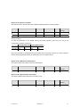
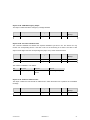
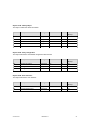
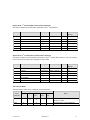
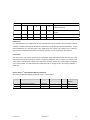
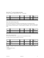
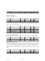
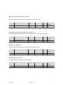
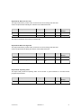
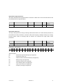
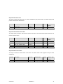
1
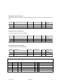
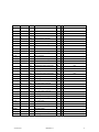
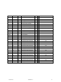
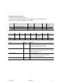
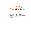
ABSOLUTE ROTAR Y ENCO DER W ITH CANOPEN INT ERFACE
USER MANUAL
Main Features
Programmable Parameters
-
Compact and heavy-duty industrial design
-
Direction of rotation (complement)
-
Interface:
CANopen (DS406)
-
Resolution per revolution
CANopen Lift (DSP417)
-
Total resolution
36 mm
-
Preset value
-
Housing:
-
Solid shaft: 6 or 10mm
-
Two limit switches and eight cams
-
Blind hollow shaft: 6mm
-
Baud rate and CAN-identifier
-
Max. 4096 steps per revolution (12 Bit)
-
Transmission mode: Polled mode, cyclic
-
Max. 32768 revolutions (15 Bit)
-
Code:
-
Velocity Output
-
LSS services
mode, sync mode
Binary
Mechanical Structure
Electrical Features
-
Programmable Termination Resistor
-
Polarity inversion protection
-
Aluminium flange and housing
-
Over-voltage-peak protection
-
Nickel-plated steel housing
-
Galvanic Isolation
Stainless steel shaft
Precision ball bearings
POSITAL GmbH
Carlswerkstraße 13c, D-51063 Köln, Telefon +49(0)221-96213-0, Telefax +49(0)221-96213-20
www.posital.eu, [email protected]
Table of Contents
Main Features ........................................................ 1
Mechanical Structure ............................................. 1
5.2 Communication Profile DS301 specific
objects from 1000h - 1FFFh ................................ 18
Programmable Parameters .................................... 1
Electrical Features ................................................. 1
5.3 Manufacturer specific objects 2000h –
5FFFh .................................................................. 19
Absolute ROTARY ENCODER WITH CANopen
Interface ............................................................ 1
5.4 Application specific objects 6000h – 67FEh .. 19
5.5 Object Descriptions ....................................... 20
USER MANUAL ................................................ 1
Table of Contents................................................. 2
Object 1000h: Device Type ................................. 20
Object 1001h: Error Register ............................... 21
General Security Advise ...................................... 4
About this Manual ................................................ 4
Object 1003h: Pre-Defined Error Field ................ 21
Object 1005h: COB-ID Sync ................................ 22
1. Introduction ...................................................... 5
1.1 General CANopen Information ......................... 5
Object 1008h: Manufacturer Device Name .......... 22
Object 1009h: Manufacturer Hardware Version... 22
2. Installation ........................................................ 7
2.1 Electrical Connection ....................................... 7
Object 100Ah: Manufacturer Software Version.... 22
Object 100Ch: Guard Time .................................. 23
3. Technical Data.................................................. 9
Electrical Data ........................................................ 9
Object 100Dh: Life Time Factor ........................... 23
Object 1010h: Store Parameters ......................... 23
Sensor data............................................................ 9
Tab. 3 Sensor data ................................................ 9
Object 1011h: Restore Parameters ..................... 24
Object 1012h: COB-ID Time Stamp Object ......... 24
Flange .................................................................. 10
Synchro (S) .......................................................... 10
Object 1013h: High Resolution Time Stamp ........ 24
Object 1014h: COB-ID Emergency Object .......... 25
Blind hollow shaft (B) ........................................... 10
Clamp (C) ............................................................ 10
Object 1016h: Consumer Heartbeat Time ........... 25
Object 1017h: Producer Heartbeat Time ............. 25
Minimum Mechanical Lifetime .............................. 10
Cable ................................................................... 10
Object 1018h: Identity Object .............................. 26
Object 1020h: Verify configuration ....................... 26
4. Configuration ................................................. 11
4.1 Operating Modes ........................................... 11
Object 1029h: Error behaviour............................. 26
st
Object 1800h: 1 Transmit PDO Communication
4.1.1 General ....................................................... 11
4.1.2 Mode: Preoperational .................................. 11
Parameter ............................................................ 27
nd
Object 1801h: 2 Transmit PDO Communication
4.1.3 Mode: Start - Operational ............................ 11
4.1.4 Mode: Stopped............................................ 11
Parameter ............................................................ 27
Event Timer ......................................................... 28
4.1.2 Reinitialization of the Encoder..................... 12
4.2 Normal Operating........................................... 12
Object 1A00h: 1 Transmit PDO Mapping
Parameter ............................................................ 28
4.3 Storing Parameter .......................................... 13
4.3.1 List of storable Parameter ........................... 13
Object 1A01h: 2
Transmit PDO Mapping
Parameter ............................................................ 29
4.3.1 Storing Procedure ....................................... 13
4.4 Restoring Parameters .................................... 14
Object 1F50h: Download Program Area .............. 29
Object 1F51h: Program Control ........................... 29
4.5 Usage of Layer Setting Services (LSS) .......... 14
5. Programmable Parameters ........................... 16
Object 2000h: Position Value .............................. 30
Object 2100h: Operating Parameters .................. 30
5.1 Programming example: Preset Value ............ 17
5.1.1 Set Encoder Preset Value ........................... 17
Object 2101h: Resolution per Revolution ............ 31
Object 2102h: Total Resolution ........................... 31
st
nd
Object 2103h: Preset Value ................................. 32
Version 02/09
UME-MCD-CA
2
Object 2104h: Limit Switch, min. .......................... 32
Object 2105h: Limit Switch, max. ......................... 33
Object 6302h: Cam polarity register .................... 40
Object 6400h: Area state register ........................ 43
Object 2160h: Customer storage ......................... 33
Object 2200h: Cyclic Timer PDO ......................... 34
Object 6401h: Work area low limit ....................... 44
Object 6402h: Work area high limit ...................... 44
Object 2300h: Save Parameter with Reset .......... 34
Object 3000h: Node Number ............................... 34
Object 6500h: Operating status ........................... 44
Object 6501h: Single-turn resolution ................... 45
Object 3001h: Baudrate ....................................... 35
Object 3002h: Termination Resistor..................... 35
Object 6502h: Number of distinguishable
revolutions ........................................................... 45
Object 3010h: Speed Control ............................... 35
Object 3011h: Speed Value ................................. 36
Object 6503h: Alarms .......................................... 45
Object 6504h: Supported alarms ......................... 46
Object 3020h: Acceleration Control ..................... 36
Object 3021h: Acceleration Value ........................ 36
Object 6505h: Warnings ...................................... 46
Object 6506h: Supported warnings ..................... 47
Object 4000h: Bootloader Control ........................ 36
Object 6000h: Operating parameters ................... 37
Object 6507h: Profile and software version ......... 47
Object 6508h: Operating time .............................. 47
Object 6001h: Measuring units per revolution ...... 38
Object 6002h: Total measuring range in
Object 6509h: Offset value .................................. 48
Object 650Ah: Module identification .................... 48
measuring units.................................................... 38
Object 6003h: Preset value .................................. 38
Object 650Bh: Serial number............................... 48
6. Diagnosis ....................................................... 49
Object 6004h: Position value ............................... 38
Object 6030h: Speed Value ................................. 39
6.2 Troubleshooting ............................................. 49
Appendix A: Order Codes ................................. 50
Object 6040h: Acceleration Value ........................ 39
Object 6200h: Cyclic timer ................................... 39
Appendix B: History .......................................... 51
Appendix C: Glossary ....................................... 52
Object 6300h: Cam state register ........................ 40
Object 6301h: Cam enable register ..................... 40
Appendix D: List of tables ................................ 55
Appendix E: Document history ........................ 55
Version 02/09
UME-MCD-CA
3
General Security Advise
Important Information
This is the safety alert symbol. It is
Read these instructions carefully, and look at the
used to alert you to potential
equipment to become familiar with the device
personal injury hazards. Obey all
before trying to install, operate, or maintain it.
safety messages that follow this symbol to avoid
The following special messages may appear
possible injury or death.
throughout
this
documentation
or
on
the
equipment to warn of potential hazards or to call
Please Note
attention to information that clarifies or simplifies
Electrical equipment should be serviced only by
a procedure.
qualified personnel. No responsibility is assumed
by POSITAL for any consequences arising out of
The addition of this symbol to a
the use of this material. This document is not
Danger or Warning safety label
intended as an instruction manual for untrained
indicates that an electrical hazard
people.
exists, which will result in personal injury if the
instructions are not followed.
About this Manual
Background
This user manual describes how to install and
Copyright
configure an MCD absolute rotary encoder with
The company POSITAL GmbH claims copyright
CANopen interface.
on this documentation. It is not allowed to
modify, to extend, to hand over to a third party
Relate Note
Version date:
and to copy this documentation without written
08. October 2010
Version number: 10/10
Reference number:
approval by the company POSITAL GmbH. Nor
is any liability assumed for damages resulting
UKE20101008
from the use of the information contained herein.
Further, this publication and features described
Imprint
herein are subject to change without notice.
POSITAL GmbH
Carlswerkstrasse 13c
User Annotation
D-51063 Köln
The POSITAL GmbH welcomes all readers to
Telefon +49 (0) 221 96213-0
send us feedback and commands about this
Telefax +49 (0) 221 96213-20
document. You can reach us by e-mail at
Internet http://www.posital.eu
[email protected]
e-mail
[email protected]
Version 02/09
UME-MCD-CA
4
Typical Applications:
1. Introduction
• Packing Machines
This manual explains how to install and
• Mobile Machines
configure the MAGNETOCODE absolute rotary
• Wind Mills
encoder with CANopen interface applicable for
• Medical Equipment
both military and industrial applications with
CANopen interface. The products are fully
1.1 General CANopen Information
compliant with standard DS406.
The CANopen system is used in industrial
applications. It is a multiple access system
(maximum: 127 participants), which means that
Measuring System
determine
all devices can access the bus. In simple terms,
positions using the Hall effect sensor
each device checks whether the bus is free, and
Magnetic
rotary
encoder
technology developed for the automotive
mass market. A permanent magnet fixed to
the shaft generates a magnetic field that is
sampled
by
the
Hall
sensor,
which
if it is the device is able to send messages. If two
devices try to access the bus at the same time,
the device with the higher priority level (lowest
ID number) has permission to send its message.
Devices with the lowest priority level must delay
translates the measured value into a unique
their data transfer and wait before retrying to
absolute position value.
send their message. Data communication is
carried out via messages. These messages
To register revolutions even when no
consist of 1 COB-ID followed by a maximum of 8
voltage is applied, energy from the turning
bytes of data. The COB-ID, which determines
of
the
shaft must suffice for proper
operation.
An
innovative,
patented
technology makes this feasible even at low
rotational
speeds
and
through
long
standstill periods – a Wiegand wire ensures
the priority of the message, consists of a
function code and a node number. The node
number corresponds to the network address of
the device. It is unique on a bus. The function
code varies according to the type of message
being sent:
that the magnetic field can only follow the
turning of the shaft in discrete steps. A coil
Management messages (LMT, NMT)
wound on the Wiegand wire receives only
Messaging and service (SDOs)
brief, strong voltage spikes, which prompt
Data exchange (PDOs)
the reliable recognition of each revolution.
Layer Setting Services (LSS)
Predefined messages (synchronization,
emergency messages)
Version 02/09
UME-MCD-CA
5
The absolute rotary encoder supports the
Further information is available at:
following operating modes:
CAN in Automation (CiA) International Users
and Manufacturers Group e.V.
Polled mode: The position value is only
Kontumazgarten 3
sent on request.
DE-90429 Nurenberg
Cyclic mode: The position value is sent
cyclically (regular, adjustable interval)
(*) Reference:
on the bus.
Industrial Applications
a
synchronization
message
Application
Layer
for
CiA Draft Standard 201 ... 207, Version
SYNC mode: The position value is sent
after
CAN
1.1
(SYNC) is received. The position value
CAL-based
Communication
is sent every n SYNCs (n ≥ 1).
Industrial Systems
Profile
for
CiA Draft Standard 301
Other functions (offset values, resolution, etc)
CiA Draft Standard 305 Layer Setting
can be configured. The absolute rotary encoder
Services
corresponds to the class 2 encoder profile (DS
CiA Draft Standard 406 Device Profile
406 in which the characteristics of encoder with
for Encoders
CANopen interface are defined). The node
number and speed in bauds are determined by
Note: All datasheets and manuals can be
their corresponding object dictionary entries.
downloaded
The
transmission
speed
can
range
from
for
free
from
our
website
www.posital.eu
20kBaud up to 1Mbaud (30m cable for a
maximum speed of 1Mbaud, 1000m cable for a
We
do
not
assume
maximum speed of 20 kbaud). Various software
technical
tools for configuration and parameter-setting are
Specifications are subject to change without
available from different suppliers. It is easy to
notice.
inaccuracies
responsibility
or
for
omissions.
align and program the rotary encoders using the
EDS (electronic data sheet) configuration file
provided.
Version 02/09
UME-MCD-CA
6
2. Installation
2.1 Electrical Connection
Function
Wire end
Connector Pin RJ45
Connector Pin M12
Can High
white
1
4
Can Low
brown
2
5
Can-GND
green
3
1
GND
yellow
4
3
red
8
2
+ Ub= 10-30 V
Tab.1 Signal Assignment Connector / Cable
5 pin male M12 connector
4
RJ45 Connector
3
5
1
Version 02/09
2
UME-MCD-CA
7
Setting Node Number via SDO Objects
The node number has to be adjusted via SDO
the node number, object 3000h has to be
objects. The default node number is 32. To set
written. For further information regard
chapter
5.5
Object
Dictionary.
Setting Baud Rate via SDO Objects
The baud rate has to be adjusted via SDO
further information please regard chapter 5.5
objects. The default baud rate is 125 kBaud. To
Object Dictionary.
set baud rate object 3001h has to be written. For
Setting Node Number via LSS
The node number can also be adjusted via
Layer Setting
Services
(LSS). For further
information regard chapter 4.5
Setting Baud Rate via LSS
The baud rate can also be adjusted via Layer
Setting Services (LSS). The default baud rate is
125 kBaud. For further information regard
chapter 4.5.
Bus Termination
If the encoder is the last device in the bus you
can use the internal termination resistor which
can
be
Version 02/09
enabled
with
an
SDO
object..
UME-MCD-CA
8
3. Technical Data
In the following section you will find general technical data about MCD absolute rotary encoders with
CANopen interface.
Electrical Data
Interface
Transceiver according ISO 11898,
galvanically isolated by opto-couplers
Transmission rate
max. 1 MBaud
Device addressing
Adjustable by SDO telegrams or Layer Setting Services
Supply voltage
10 – 30* V DC (absolute limits)
Current consumption
max. 100 mA with 10 V DC, max. 50 mA with 24 V DC
Power consumption
max. 1,2 Watts
EMC
Emitted interference:
EN 61000-6-4
Noise immunity:
EN 61000-6-2
Electrical lifetime
5
> 10 h
Tab. 2 Electrical Data
*Absolute rotary encoders should be connected only to subsequent electronics whose power supplies comply with EN
50178 (protective low voltage)
Sensor data
Singleturn technology
magnetic 2 axis Hall sensor
Singleturn resolution
up to 4096 steps / revolution (12 Bit)
Singleturn accuracy
+/-0,35°
Internal cycle time
< 1 ms
Multiturn technology
self supplied magnetic pulse counter
Multiturn resolution
Can measure up to 200 Billion revolutions
Tab. 3 Sensor data
Environmental Conditions
Operating temperature
- 30 ... + 85 °C (M12 connector version
- 30 ... + 70 °C (Cable exit version) *
Storage temperature
- 30 ... + 85 °C (M12 connector version
- 30 ... + 70 °C (Cable exit version) *
Humidity
98 % (without liquid state)
Protection Class (EN 60529)
Casing side: IP54 (Cable exit version)
IP65 (M12 Connector version)
Shaft side:
IP65
Tab.4 Environmental Conditions
Version 02/09
UME-MCD-CA
9
Mechanical Data
Housing
Nickel-plated iron housing
Flange
Aluminium
Shaft
Stainless steel
Lifetime
Dependent on shaft version and shaft loading – refer to table
Max. shaft loading
Axial 40 N, radial 110 N
2
Inertia of rotor
30 gcm
Friction torque
3 Ncm
RPM (continuous operation)
max. 12.000 RPM
Shock (EN 60068-2-27)
100 g (half sine, 6 ms)
Permanent shock (EN 60028-2-29)
10 g (half sine, 16 ms)
Vibration (EN 60068-2-6)
10 g (10 Hz ... 1,000 Hz)
Weight (standard version)
150 g, including cable
Flange
Shaft diameter
Shaft length
Hollow shaft depth min. / max.
Synchro (S)
Blind hollow shaft (B)
Clamp (C)
6 mm
6 mm
10 mm
11,5 mm
-
20 mm-
-
8 mm / 18 mm
-
Tab. 5 Mechanical data
Minimum Mechanical Lifetime
8
Flange
Lifetime in 10 revolutions with Fa / Fr
S06 (Synchro flange 6 x 11.5)
40 N / 60 N
40 N / 80 N
40 N / 110 N
216
91
35
Tab. 6 Minimum Mechanical Lifetime
Cable
Operating temperature cable
flexing -5°C bis +70°C
static -30°C bis +70°C
Minimum bend radius
flexing 10x cable diameter
static 5x cable diameter
Cable
aprox 6 mm
/ type : LIYCY 4x2x0.14
Tab.7 Cable properties
Version 02/09
UME-MCD-CA
10
4. Configuration
The purpose of this chapter is to describe the configuration parameters of the absolute rotary encoder with
CANopen interface.
4.1 Operating Modes
4.1.1 General
The encoder accesses the CAN network after
preoperational
powerup in pre-operational mode:
entails reduced activity on the network, which
mode.
Pre-operational
mode
BootUp Message: 700 hex + Node Number
simplifies the checking of the accuracy of the
sent/received SDOs. It is not possible to send or
It is recommended that the parameters can be
receive
PDOs
in
pre-operational
mode.
changed by the user when the encoder is in
4.1.2 Mode: Preoperational
To set a node to pre-operational mode, the master must send the following message:
Identifier
Byte 0
Byte 1
Description
0h
80 h
00
NMT-PreOp, all nodes
0h
80 h
NN
NMT-PreOp, NN
NN: node number
It is possible to set all nodes (Index 0) or a single node (Index NN) to pre-operational mode.
4.1.3 Mode: Start - Operational
To put one or all nodes in the operational state, the master have to send the following message:
Identifier
Byte 0
Byte 1
Description
0h
01 h
00
NMT-Start, all nodes
0h
01 h
NN
NMT-Start, NN
NN: node number
It is possible to set all nodes (Index 0) or a single node (Index NN) to operational mode.
4.1.4 Mode: Stopped
To put one or all nodes in the stopped state, the master have to send the following message:
Identifier
Byte 0
Byte 1
Description
0h
02 h
00
NMT-Stop, all nodes
0h
02 h
NN
NMT-Stop, NN
Version 02/09
UME-MCD-CA
11
NN: node number
It is possible to set all nodes (Index 0) or a single node (Index NN) to stop mode.
4.1.2 Reinitialization of the Encoder
If a node is not operating correctly, it is advisable to carry out a reinitialization:
NN
Command
Index
Description
0h
82 h
00
Reset Communication
0h
81 h
NN
Reset Node
NN: node number
It is possible to set all nodes (Index 0) or a single node (Index NN) in reset mode.
After reinitialization, the encoder accesses the bus in pre-operational mode.
4.2 Normal Operating
Polled Mode
By a remote-transmission-request telegram the connected host calls for the
current process value. The encoder reads the current position value,
calculates eventually set-parameters and sends back the obtained process
value by the same identifier.
Cyclic Mode
The encoder transmits cyclically - without being called by the host - the
current process value. The cycle time can be programmed in milliseconds
for values between 1 ms and 65536 ms.
Sync Mode
After receiving a sync telegram by the host, the encoder answers with the
current process value. If more than one node number (encoder) shall
answer after receiving a sync telegram, the answer telegrams of the nodes
will be received by the host in order of their node numbers. The
programming of an offset-time is not necessary. If a node should not answer
after each sync telegram on the CAN network, the parameter sync counter
can be programmed to skip a certain number of sync telegrams before
answering again.
Tab. 8 CAN Transmission Mode Description
Version 02/09
UME-MCD-CA
12
4.3 Storing Parameter
4.3.1 List of storable Parameter
Object Index
Object Description
1005h
COB-ID Sync
100Ch
Guard Time
100Dh
Life Time Factor
1016h
Consumer Heartbeat Time
1017h
Producer Heartbeat Time
1020h
Verify configuration
1800h
Communication parameter PDO 1
1801h
Communication parameter PDO 2
1A00h
Transmit PDO1 Mapping Parameter
1A01h
Transmit PDO2 Mapping Parameter
2100h
Operating Parameters
2101h
Resolution per Revolution
2102h
Total Resolution
2103h
Preset Value
2104h
Limit Switch, min.
2105h
Limit Switch, max.
2160h
Customer Storage
2200h
Cyclic Timer
3000h
Node Number
3001h
Baud rate
3002h
Termination Resistor
6000h
Operating Parameter
6001h
Steps per Revolution
6002h
Total Resolution
6003h
Preset Value
6200h
Cyclic Timer
Tab. 9 List of Storable Parameters
4.3.1 Storing Procedure
Version 02/09
UME-MCD-CA
13
The parameter settings can be stored in a non-
by the parameter memory transfer. The
2
volatile E PROM. The parameter settings are
stored parameters are copied after a RESET
stored in RAM when being programmed. When
(Power on, NMT-Reset) from the E PROM to
all the parameters are set and proved, they can
2
the RAM (volatile memory).
2
be transferred in one burn cycle to the E PROM
Storing without Reset
By
using
the
object
1010h
from
the
communication profile related object dictionary
you can store the parameters into the nonvolatile
memory
without
a
reset.
Storing with Reset
By using the object 2300h from the manufacturer
storing the parameters a reset of the device is
specific object dictionary you can store the
performed.
parameters into the non-volatile memory. After
4.4 Restoring Parameters
The default parameters can be restored by using
parameter the following telegram is used. The
the object 1011h from communication profile
restored parameters are equal for every type of
related object dictionary. The already in the non-
CANopen encoder and might not fit with the
volatile memory programmed parameters are
status after delivery. Please check the restored
not overwritten. Only after a new store command
parameters before you store them to the non-
the default parameters are stored in the non-
volatile memory.
volatile
memory.
To
restore
the
default
4.5 Usage of Layer Setting Services (LSS)
To configure the encoder via LSS the encoder
device. After receiving this information the
will be the LSS slave device and the control has
control can unequivocally identify the encoder
to support LSS master device functionality.
and the node number and baud rate can be set.
The LSS master device requests services, that
are performed by the LSS slave devices
(encoder). The LSS master device requests the
LSS address (vendor-id, product-code, revisionnumber, serial-number) from the LSS slave
Version 02/09
UME-MCD-CA
14
Version 02/09
UME-MCD-CA
15
5. Programmable Parameters
Objects are based on the CiA 406 DS V3.2: CANopen profile for encoders (www.can-cia.org)
Command
Function
Telegram
Description
22h
Domain Download
Request
Parameter to Encoderr
23h, 27h, 2Bh, 2Fh (*)
Domain Download
Request
60h
Domain Download
Confirmation
Parameter received
40h
Domain Upload
Request
Parameter request
43h, 47h, 4Bh, 4Fh (*)
Domain Upload
Reply
80 h
Warning
Reply
Parameter to Encoder (Bytes
indicated)
Parameter to Master (Bytes
indicated)
Transmission error
Tab. 10 General Command Byte Description
(*)The value of the command byte depends on the data length of the called parameter:
Command
Data length
Data type
Command
Data length
Data type
43h
4 Byte
Unsigned 32
23h
4 Byte
Unsigned 32
47h
3 Byte
Unsigned 24
27h
3 Byte
Unsigned 24
4Bh
2 Byte
Unsigned 16
2Bh
2 Byte
Unsigned 16
4Fh
1 Byte
Unsigned 8
2Fh
1 Byte
Unsigned 8
Tab. 11 Detailed Command Byte Description
Object Dictionary
The data transmission according to CAL is realized
Index (hex)
Object
exclusively by object oriented data messages. The
0000
not used
objects are classified in groups by an index record.
0001-001F
Static Data Types
Each index entry can be subdivided by sub-indices.
0020-003F
Complex Data Types
0040-005F
Manufacturer Specific Data Types
0060-0FFF
Reserved for further use
1000-1FFF
Communication Profile Area
2000-5FFF
Manufacturer Specific Profile Area
6000-9FFF
Standardized Device Profile Area
A000-FFFF
Reserved for further use
The overall layout of the standard object dictionary is
shown beside:
Tab. 12 Overview Object Dictionary
Version 02/09
UME-MCD-CA
16
5.1 Programming example: Preset Value
If a CANopen device is connected and configured with the right baudrate and also configured to a unused
node number, it will start up into the pre-operational mode and send a bootup massage to the master.
5.1.1 Set Encoder Preset Value
Master to Encoder with Node Number 1
Setting Preset Value (Value 1000)
Identifier
DLC
NN 1
601
8
Command
Index
Subindex
Download
6003h
22
03
Command
Index
Download
6003h
43
03
60
Service/Process data
Byte 4
Byte 5
Byte 6
Byte 7
00
00
10
00
00
Subindex
Service/Process data
Answer of the Encoder
Identifier
DLC
NN 1
581
8
60
Byte 4
Byte 5
Byte 6
Byte 7
00
00
00
00
00
Subindex
Service/Process data
Read Preset Value from the Encoder
Identifier
DLC
NN 1
601
8
Command
Index
Download
6003h
40
03
Command
Index
Download
6003h
43
03
Command
Index
Download
1010h
22
10
60
Byte 4
Byte 5
Byte 6
Byte 7
00
00
00
00
00
Subindex
Service/Process data
Answer of the Encoder
Identifier
DLC
NN 1
581
8
60
Byte 4
Byte 5
Byte 6
Byte 7
00
00
10
00
00
Subindex
Service/Process data
Save Preset Values
Identifier
DLC
NN 1
601
Version 02/09
8
10
UME-MCD-CA
01
Byte 4
Byte 5
Byte 6
Byte 7
73
61
76
65
17
5.2 Communication Profile DS301 specific objects from 1000h - 1FFFh
In this manual we refer to the communication profile DS301 V4.02
Object Description
Page
Page
Hand-
DS301
Page
DS406
Book
1000h
Device type
22
86
8
1001h
Error register
22
87
8
1003h
Pre-defined error field
22
88
1005h
COB-ID SYNC-message
23
89
1006h
ComCyclePeriode
23
90
1008h
Device name
24
91
1009h
Hardware version
24
91
100Ah
Software version
24
91
100Ch Guard Time
24
92
100Dh Life Time Factor
24
92
1010h
Store parameters
25
92
1011h
Restore default parameters
25
94
1012h
COB-ID Time Stamp
26
97
1013h
High Resolution Time Stamp
26
98
1014h
COB-ID Emergency
26
98
1016h
Consumer Heartbeat Time
26
100
1017h
Producer Heartbeat Time
27
101
1018h
Identity Object
27
101
1020h
Verify Configuration
117
1029h
Error Behaviour
133
9
1800h
Communication parameter PDO 1
28
111
9
1801h
Communication parameter PDO 2
28
111
11
1A00h
Transmit PDO1 Mapping Parameter
30
112
11
1A01h
Transmit PDO2 Mapping Parameter
30
112
12
1F50h
Download Program Area
1F51h
Program Control
Tab. 13 Object Dictionary 1000h-1FFFh
Version 02/09
UME-MCD-CA
18
5.3 Manufacturer specific objects 2000h – 5FFFh
Object Description
Page
Hand-Book
2000h
Position Value
31
2100h
Operating Parameters
31
2101h
Resolution per Revolution
31
2102h
Total Resolution
33
2103h
Preset Value
34
2104h
Limit Switch, min.
34
2105h
Limit Switch, max.
33
2160h
Customer Storage
35
2200h
Cyclic Timer
35
2300h
Save Parameter with reset
35
3000h
Node Number
36
3001h
Baudrate
36
3002h
Termination Resistor
36
3010h
Speed Control
37
3011h
Speed Value
37
3020h
Acceleration Control
37
3021h
Acceleration Value
37
4000h
Bootloader Control
38
Tab. 14 Object Dictionary 2000-5FFF
5.4 Application specific objects 6000h – 67FEh
In this manual we refer to the communication profile DS406 V3.2
Object Description
Page
Hand-Book
Page
DS406
6000h
Operating Parameters
38
17
6001h
Measuring units per revolution
38
18
6002h
Total measuring range in measuring units
39
19
6003h
Preset value
39
19
6004h
Position Value
40
20
6030h
Speed Value
40
25
6040h
Acceleration Value
40
26
6200h
Cyclic Timer
40
28
Version 02/09
UME-MCD-CA
19
6300h
Cam state register
40
30
6301h
Cam enable register
41
32
6302h
Cam polarity register
41
33
6400h
Area state register
44
6401h
Work area low limit
44
6402h
Work area high limit
44
6500h
Operating status
45
63
6501h
Single-turn resolution
45
64
6502h
Number of distinguishable revolutions
45
65
6503h
Alarms
46
65
6504h
Supported alarms
46
66
6505h
Warnings
47
67
6506h
Supported warnings
47
68
6507h
Profile and software version
48
69
6508h
Operating time
48
70
6509h
Offset value
49
70
650Ah
Module identification
49
71
650Bh
Serial number
49
72
Tab. 15 Object Dictionary 6000h-6FFFh
5.5 Object Descriptions
In the following chapter you will find detailed information of the object dictionary related to the encoder
device.
Object 1000h: Device Type
The object at index 1000h describes the type of device and its functionality. It is composed of a 16-bit field
which describes the device profile that is used and a second 16-bit field which gives additional information
about optional functionality of the device. The additional information parameter is device profile specific.
Subindex
Description
Data Type
Default Value
Access
Restore after
BootUp
0
-
Unsigned 32
N/A
ro
no
MCD absolute rotary encoder single turn: 10196h
Version 02/09
UME-MCD-CA
20
MCD absolute rotary encoder multi turn: 20196h
Object 1001h: Error Register
This object is used by the device to display internal faults. When a fault is detected, the corresponding bit
is therefore activated.
The following errors are supported:
Bit
Description
Comments
0
Generic Error
The generic error is signaled at any error situation.
Subindex
Description
Data Type
Default Value
Access
Restore after
BootUp
0
-
Unsigned 8
N/A
ro
no
Object 1003h: Pre-Defined Error Field
The object holds the errors that have occurred on the device and have been signaled via the Emergency
Object.
The error code is located in the least significant word
Additional Information is located in the most significant word
Subindex 0 contains the number of recorded errors
Subindex
Description
Data Type
Default Value
Access
Restore after
BootUp
0
Number of recorded errors
Unsigned 8
0
rw
no
1
Most recent errors
Unsigned 32
-
ro
no
2
Second to last error
Unsigned 32
-
ro
no
…
10
Clearing Error Log
The error log can be cleared by writing 0 to subindex 0 of object 1003.
Version 02/09
UME-MCD-CA
21
Object 1005h: COB-ID Sync
This object contains the synchronization message identifier.
Subindex
Description
Data Type
Default Value
Access
Restore after
BootUp
0
-
Unsigned 32
80000080h
rw
no
Data Type
Default Value
Access
Restore after
Object 1008h: Manufacturer Device Name
This object contains the device name.
Subindex
Description
BootUp
0
-
String
-
ro
no
Default Value
Access
Restore after
Object 1009h: Manufacturer Hardware Version
This object contains the article name of the circuit board.
Subindex
Description
Data Type
BootUp
0
-
String
-
ro
no
There is one actual version of circuit boards for MCD:
POS033 (MCD-CA)
Object 100Ah: Manufacturer Software Version
This object contains the manufacturer software version. The new encoder line 2008 starts with version
4.00.
Subindex
Description
Data Type
Default Value
Access
Restore after
BootUp
0
Version 02/09
-
String
UME-MCD-CA
4.00
ro
no
22
Object 100Ch: Guard Time
This object contains the guard time in milliseconds.
Subindex
Description
Data Type
Default Value
Access
Restore after
BootUp
0
-
Unsigned 16
0
rw
yes
Object 100Dh: Life Time Factor
This object contains the life time factor parameters. The life time factor multiplied with the guard time gives
the life time for the node guarding protocol.
Subindex
Description
Data Type
Default Value
Access
Restore after
BootUp
0
-
Unsigned 8
0
rw
yes
Object 1010h: Store Parameters
This object is used to store device and CANopen related parameters to non volatile memory.
Subindex
Description
Data Type
Default Value
Access
Restore after
BootUp
0
Number of sub indices
Unsigned 8
2
ro
no
1
Store all parameters
Unsigned 32
“save”
rw
no
Storing procedure
To save the parameters to non volatile memory the access signature “save” has to be sent to the
corresponding subindex of the device.
Most significant word Least significant word
ASCII
E
v
a
s
Hex value
65h
76h
61h
73h
Version 02/09
UME-MCD-CA
23
Object 1011h: Restore Parameters
This object is used to restore device and CANopen related parameters to factory settings.
Subindex
Description
Data Type
Default Value
Access
Restore after
BootUp
0
Number of sub indices
Unsigned 8
2
ro
no
1
Restore all parameters
Unsigned 32
“load”
rw
no
Storing procedure
To save the parameters to non volatile memory the access signature “load” has to be sent to the
corresponding subindex of the device.
Most significant word Least significant word
ASCII
D
a
o
l
Hex value
64h
61h
6Fh
6Ch
Note: The restoration of parameters will only be taken into account after a power up or reset command.
Please check all parameters before you store them to the non volatile memory.
Object 1012h: COB-ID Time Stamp Object
This object contains the COB-ID of the Time Stamp object.
Subindex
Description
Data Type
Default Value
Access
Restore after
BootUp
0
-
Unsigned 32
100h
rw
no
Default Value
Access
Restore after
Object 1013h: High Resolution Time Stamp
This object contains a time stamp with a resolution of 1µs.
Subindex
Description
Data Type
BootUp
0
Version 02/09
-
Unsigned 32
UME-MCD-CA
0
rw
no
24
Object 1014h: COB-ID Emergency Object
This object contains the EMCY emergency message identifier.
Subindex
Description
Data Type
Default Value
Access
Restore after
BootUp
0
-
Unsigned 32
80h + Node ID
rw
no
Object 1016h: Consumer Heartbeat Time
The consumer heartbeat time defines the expected heartbeat cycle time in ms. The device can only
monitor one corresponding device. If the time is set to 0 the monitoring is not active. The value of this
object must be higher than the corresponding time (object 1017) of the monitored device.
Subindex
Description
Data Type
Default Value
Access
Restore after
BootUp
0
Number of indices
Unsigned 8
1
ro
no
1
Consumer heartbeat time
Unsigned 32
0
rw
yes
The context of subindex 1 is as follows:
Bit
31 to 24
23 to 16
15 to 0
Value
0h (reserved)
Address of monitored Monitoring time (ms
device
Object 1017h: Producer Heartbeat Time
The object contains the time intervall in milliseconds in which the device has to produce the a heartbeat
message.
Subindex
Description
Data Type
Default Value
Access
Restore after
BootUp
0
Version 02/09
-
Unsigned 16
UME-MCD-CA
0
rw
yes
25
Object 1018h: Identity Object
This object contains the device information.
Subindex
Description
Data Type
Default Value
Access
Restore after
BootUp
0
Number of entries
Unsigned 8
4
ro
no
1
Vendor ID
Unsigned 32
42h
ro
no
2
Product Code
Unsigned 32
ro
no
3
Revision Number
Unsigned 32
ro
no
4
Serial Number
Unsigned 32
ro
no
Access
Restore after
10000h
Object 1020h: Verify configuration
This object indicates the downloaded configuration date and time.
Subindex
Description
Data Type
Default Value
BootUp
0h
Number of entries
Unsigned 8
1h
Configuration date
2h
Configuration time
2h
ro
no
Unsigned 32
rw
no
Unsigned 32
rw
no
Access
Restore after
Object 1029h: Error behaviour
This object indicates the error behavior.
Subindex
Description
Data Type
Default Value
BootUp
0h
Number of entries
Unsigned 8
1h
Communication error
Unsigned 8
Version 02/09
UME-MCD-CA
1h
ro
no
rw
no
26
st
Object 1800h: 1 Transmit PDO Communication Parameter
st
This object contains the communication parameter of the 1 transmit PDO.
Subindex
Description
Data Type
Default Value
Access
Restore after
BootUp
0
Number of sub indices
Unsigned 8
5
ro
yes
1
COB-ID
Unsigned 32
180h + Node ID
rw
yes
2
Transmission Mode
Unsigned 8
FE
rw
yes
3
Inhibit Time
Unsigned 32
0
rw
yes
4
Not available
5
Event Timer
Unsigned 32
64h or 0
rw
yes
Object 1801h: 2
nd
Transmit PDO Communication Parameter
This object contains the communication parameter of the 2
nd
transmit PDO. NOTE: In the OCD versions
C2 and C5 the second PDO was configured via object 1802!
Subindex
Description
Data Type
Default Value
Access
Restore after
BootUp
0
Number of sub indices
Unsigned 8
5
ro
yes
1
COB-ID
Unsigned 32
280h + Node ID
rw
yes
2
Transmission Mode
Unsigned 8
1
rw
yes
3
Inhibit Time
Unsigned 32
0
rw
yes
4
Not available
5
Event Timer
Unsigned 32
0
rw
yes
Transmission Mode
The transmission mode can be configured as described below:
Transmission Mode
Transfer
Value
Cyclic
Acyclic
(decimal)
0
1-240
Version 02/09
X
X
Synchro
Asynchr
RTR
nous
onous
only
Notes
Send
X
PDO on
first
Sync message
following an event
X
Send PDO every x Sync messages
UME-MCD-CA
27
241-251
reserved
252
X
X
253
X
Receive SYNC message and send PDO
on Remote Request
Update data and send PDO on Remote
Request
254
X
Send PDO on event
255
X
Send PDO on event
Inhibit Time
For "Transmit PDOs", the "inhibit time" for PDO transmissions can be entered in this 16 bit field. If data is
changed, the PDO sender checks whether an "inhibit time" has expired since the last transmission. A new
PDO transmission can only take place if the "inhibit time" has expired. The "inhibit time" is useful for
asynchronous transmission (transmission mode 254 and 255), to avoid overloads on the CAN bus.
Event Timer
The "event timer" only works in asynchronous transmission mode (transmission mode 254 and 255). If the
data changes before the "event timer" expires, a temporary telegram is sent. If a value > 0 is written in this
16-bit field, the transmit PDO is always sent after the "event timer" expires. The value is written in subindex
5 of a transmit PDO. The data transfer also takes place with no change to data. The range is between 165536 ms.
st
Object 1A00h: 1 Transmit PDO Mapping Parameter
st
This object contains the mapping parameter of the 1 transmit PDO.
Subindex
Description
Data Type
Default Value
Access
Restore after
BootUp
0
Number of sub indices
Unsigned 8
2
ro
yes
1
1st mapped object
Unsigned 32
60040020h
rw
yes
Version 02/09
UME-MCD-CA
28
Object 1A01h: 2
nd
Transmit PDO Mapping Parameter
This object contains the mapping parameter of the 2
Subindex
Description
nd
transmit PDO.
Data Type
Default Value
Access
Restore after
BootUp
0
1
Number of sub indices
2
nd
mapped object
Unsigned 8
2
ro
yes
Unsigned 32
60040020h
rw
yes
Object 1F50h: Download Program Area
This is a special object that has functionality for the bootloader feature. (see Bootloader chapter)
Use this entry to download your Intel hex file with the programming data. Detailed information about
Domain download and Block transfer in CiA Draft Standard 301 Application Layer and communication
Profile.
Subindex
Description
Data Type
Default Value
Access
Restore after
BootUp
0h
Number of sub indices
1h
Unsigned 8
2h
DOMAIN
ro
Yes
wo
yes
Object 1F51h: Program Control
This is a special bootloader object, to update the firmware (see Bootloader chapter).
This array controls the programs residing at index 0x1F50.
Subindex
Description
Data Type
Default Value
Access
Restore after
BootUp
0h
Number of program control Unsigned 8
entries
1h
Unsigned 32
2h
ro
yes
rw
yes
Sub-index 1h and higher control the memory block functionality. They can have the following values:
for writing:
1 - start downloaded program
4 - erase flash
Version 02/09
UME-MCD-CA
29
Object 2000h: Position Value
This object contains the position value.
Subindex
Description
Data Type
Default Value
Access
Restore after
BootUp
0
Position Value
Unsigned 32
-
ro
n.a.
Object 2100h: Operating Parameters
As operating parameters the code sequence (Complement) can be selected and the limit switches can be
turned on or off.
Subindex
Description
Data Type
Default Value
Access
Restore after
BootUp
0
Operating Parameters
Unsigned 8
0h
rw
yes
The parameter code sequence (Complement) determines the counting direction, in which the output
process value increases or decreases (CW = Clockwise, CCW = Counterclockwise). The code sequence
is determined by Bit 0 in Index 2100h. Additionally, the two limit switches, Min. and Max. can be turned on
or off in Index 2100h.
Bit 0
Code
Code
Bit 1
sequence
Limit switch, Bit 2
Limit
min.
max.
switch, Bit 3
Event
triggered
PDO
0
CW
increasing
0
off
0
off
0
off
1
CCW
increasing
1
on
1
on
1
on
Calculation Example: Target: Absolute rotary encoder with direction CCW increasing, limit switch min
enabled and limit switch max disabled.
Bitmatrix:
Bit 0 = 1
Direction increasing CCW
Bit 1 = 1
Limit switch min. enabled
Bit 2 = 0
Limit switch max. disabled
Result = 011b = 3h
Version 02/09
UME-MCD-CA
30
Object 2101h: Resolution per Revolution
This object contains the desired steps per revolution of the encoder.
Subindex
Description
Data Type
Default Value
Access
Restore after
BootUp
0
Resolution per Revolution
Unsigned 32
see type sign
rw
yes
n
If the desired value exceeds the hardware resolution of the encoder or is not a value of 2 , it will be out of
range. Only values in the power of two are valid, otherwise the error code “06090030h: Value range of
parameter exceeded” will appear.
Object 2102h: Total Resolution
This object contains the desired total resolution of the encoder.
Subindex
Description
Data Type
Default Value
Access
Restore after
BootUp
0
Total Resolution
Unsigned 32
see type sign
rw
yes
This parameter is used to program the desired number of measuring units over the total measuring range.
This value must not exceed the total resolution of the absolute rotary encoder, which is printed on the type
sign of the encoder.
Attention:
Following formula letter will be used:
PGA
Physical total resolution of the encoder
(see type sign)
PAU
Physical resolution per revolution
(see type sign)
GA
Total resolution
(customer parameter)
AU
Resolution per revolution
(customer parameter)
Please use the following formula to calculate the total resolution of the encoder:
Version 02/09
UME-MCD-CA
31
If the desired resolution per revolution is less than the really physical resolution per revolution of the
encoder, then the total resolution must be entered as follows:
Total resolution:
Calculation example:
Customer handicap: AU = 2048
Encoder type sign:
PGA=24 bit, PAU=12bit
If the total resolution of the encoder is less than the physical total resolution, the parameter total resolution
must be a multiple of the physical total resolution:
Object 2103h: Preset Value
The preset value is the desired position value, which should be reached at a certain physical position of
the axis. The position value is set to the desired process value by the parameter preset. The preset value
must not exceed the parameter total resolution to avoid run-time errors. If the parameter value exceeds the
total resolution of the encoder a SDO “Out of range” message is generated.
Subindex
Description
GA
Data Type
Default Value
Access
Restore after
BootUp
0
Preset Value
Object 2104h: Limit Switch, min.
Unsigned 32
0
rw
yes
Two position values can be programmed as limit switches. By reaching this value, one bit of the 32 bit
process value is set to high. Both programmed values must not exceed the parameter total resolution to
avoid run-time errors. If the parameter value exceeds the total resolution of the encoder a SDO “Out of
range” message is generated.
Bit 30 = 1:
Subindex
Limit Switch, Min. reached or passed under
Description
Data Type
Default Value
Access
Restore after
BootUp
0
Version 02/09
Limit Switch, min.
Unsigned 32
UME-MCD-CA
0
rw
yes
32
The limit switch, Min sets Bit 30=1 with the next message telegram, if the process value reaches or passes
under the value of the limit switch:
Status
Function bits
Bit
Process value
31 30 29 28 27 26 25 24 23 22 21 20 19 18 17 16 15 14 13 12 11 10 9 8 7 6 5 4 3 2 1 0
0
1
X X X X X X X X X X X X X X X X X X X X X X X X X X X X X X
Object 2105h: Limit Switch, max.
Two position values can be programmed as limit switches. By reaching this value, one bit of the 32 bit
process value is set to high. Both programmed values must not exceed the parameter total resolution to
avoid run-time errors. If the parameter value exceeds the total resolution of the encoder a SDO “Out of
range” message is generated.
Bit 31 = 1:
Limit Switch, Max. reached or passed beyond
Subindex
Description
Data Type
Default Value
Access
Restore after
BootUp
0
Limit Switch, max.
Unsigned 32
0
rw
yes
The limit switch, max sets Bit 31=1 with the next message telegram, if the process value reaches or
passes under the value of the limit switch:
Status
Function bits
Bit
Process value
31 30 29 28 27 26 25 24 23 22 21 20 19 18 17 16 15 14 13 12 11 10 9 8 7 6 5 4 3 2 1 0
1
0
X X X X X X X X X X X X X X X X X X X X X X X X X X X X X X
Object 2160h: Customer storage
This object provides for the customer the possibility to store any value.
Subindex
Description
Data Type
Default Value
Access
Restore after
BootUp
0h
Number of sub indices
Unsigned 8
1h
Customer Storage1
Unsigned 32
Version 02/09
UME-MCD-CA
4h
ro
rw
33
2h
Customer Storage2
Unsigned 32
rw
3h
Customer Storage3
Unsigned 32
rw
4h
Customer Storage4
Unsigned 32
rw
Object 2200h: Cyclic Timer PDO
This object contains cyclic time of the event timer in ms (of PDO 1).
Subindex
Description
Data Type
Default Value
Access
Restore after
BootUp
0h
Event Time in ms
Unsigned 16
0h
ro
yes
The object 2200h is hard-wired to the objects 1800h subindex 5h and 6200h and provide the cycle time for
the cyclic mode. (See chapter Cycle Time and Event Timer)
Object 2300h: Save Parameter with Reset
With this object all parameters can be stored in the non volatile memory. After storing the parameters a
reset is executed.
Subindex
Description
Data Type
Default Value
Access
Restore after
BootUp
0
Access code
Unsigned 32
55AAAA55h
wo
no
Object 3000h: Node Number
This object contains the node number of the device. The POSITAL standard node number is 32.
Subindex
Description
Data Type
Default Value
Access
Restore after
BootUp
0
Node Number
Unsigned 8
1Fh
rw
Yes
NOTE: To avoid the node number 0, one will be added to the value of this object!
E.g.: 1Fh+1h = 20h = 32 (dec)
Version 02/09
UME-MCD-CA
34
Object 3001h: Baudrate
This object contains the baudrate of the device.
Subindex
Description
Data Type
Default Value
Access
Restore after
BootUp
0
Baudrate
Unsigned 8
-
rw
yes
Eight different baud rates are provided. To adjust the baud rate only one byte is used.
Baudrate in kBit/s
Byte
20
00h
50
01h
100
02h
125
03h
250
04h
500
05h
800
06h
1000
07h
Object 3002h: Termination Resistor
Subindex
Description
Data Type
Default Value
Access
Restore after
BootUp
0
Termination Resistor
Unsigned 8
-
rw
yes
By writing 01h to this object the internal galvanic isolated termination resistor is activated. Note that the
resistor is only activated when the device is powered. If you have more CAN nodes on the Bus be sure to
power them approx 700ms after the device with the programmed termination Resistor.
Object 3010h: Speed Control
This object contains the speed control. The speed measurement is disabled by default.
Subindex
Description
Data Type
Default Value
Access
Restore after
BootUp
0h
Number of sub indices
Unsigned 8
2h
ro
1h
Enable Speed
Unsigned 8
0h
rw
Version 02/09
UME-MCD-CA
yes
35
2h
Speed modus
Unsigned 8
0h
rw
yes
Data Type
Default Value
Access
Restore after
Object 3011h: Speed Value
This object contains speed value.
Subindex
Description
BootUp
0h
Speed value
Unsigned 8
romap
no
Object 3020h: Acceleration Control
This object contains the acceleration control. Acceleration output is not supported by this device. This
object is present only for compatibility reasons.
Subindex
Description
Data Type
Default Value
Access
Restore after
BootUp
0h
Number of sub indices
Unsigned 8
2h
Ro
1h
Enable Acceleration
Unsigned 8
0h
rw
Yes
2h
Acceleration modus
Unsigned 8
0h
rw
yes
Object 3021h: Acceleration Value
Acceleration output is not supported by this device. This object is present only for compatibility reasons.
Subindex
Description
Data Type
Default Value
Access
Restore after
BootUp
0h
Acceleration Value
INTEGER32
romap
Object 4000h: Bootloader Control
This object controls the Bootloader functionality (see Bootloader chapter). Writing the security code to this
object causes erasing the EEPROM and application information in the flash memory and resets the device.
After a power-up, the Bootloader checks the user application and detects no more information. The
Bootloader starts up with a pre-defined CANopen node ID of 1 (0x1) and a fixed CAN baud rate of 125
kbits.
Subindex
Description
Data Type
Default Value
Access
Restore after
BootUp
0h
Version 02/09
Bootloader Control
Unsigned32
UME-MCD-CA
wo
36
NOTE:
Activating the Bootloader courses a deep reset of the device. After this only a few objects are still
available, the device does not behave like an encoder and waits for new programming. That is the reason
why the security code is not published in this document. Please contact POSITAL to obtain the code.
Object 6000h: Operating parameters
This object shall indicate the functions for code sequence, commissioning diagnostic control
and scaling function control.
Subindex
Description
Data Type
Default Value
Access
Restore after
BootUp
0h
Operating Parameter
Unsigned 16
1h
rw
yes
Code sequence: The code sequence defines, whether increasing or decreasing position values are output,
in case the encoder shaft rotates clockwise or counter clockwise as seen from the point of view of the
shaft.
Scaling function control: With the scaling function the encoder numerical value is converted in software to
change the physical resolution of the encoder. The measuring units per revolution (object 6001h) and total
measuring range in measuring units (object 6002h) are the scaling parameters. The scaling function bit is
set in the operating parameters. If the scaling function bit is set to zero, the scaling function is disabled.
Bit structure for the operating parameters
Bit
15
14
13
12
11
10
9
8
7
6
5
4
3
2
1
Use
MS
MS
MS
MS
R
R
R
R
R
R
R
R
MD
SFC CD
0
CS
Table Description:
MS:
Manufacturer Specific Function (not available)
R:
Reserved for future use
MD:
Measuring direction (not available)
SFC:
Scaling function (0 = disable, 1 = enable)
CD:
Commissioning diagnostic control (not availabe)
CS:
Code sequence (0 = CW Up, 1 = CCW Up)
Code Sequence (CS Bit 0) is hardwired to Code Sequence (CS Bit 0) in object 2100h.
Version 02/09
UME-MCD-CA
37
Object 6001h: Measuring units per revolution
This object shall indicate the number of distinguishable steps per revolution.
Subindex
Description
Data Type
Default Value
Access
Restore after
BootUp
0h
Measuring units per revolution
Unsigned 32
see type sign
rw
yes
Hardwired with 2101h.
Object 6002h: Total measuring range in measuring units
This object shall indicate the number of distinguishable steps over the total measuring range.
Subindex
Description
Data Type
Default Value
Access
Restore after
BootUp
0h
Total measuring steps
Unsigned 32
see type sign
rw
yes
Access
Restore after
Object 6003h: Preset value
This object indicates the preset value for the output position value
Subindex
Description
Data Type
Default Value
BootUp
0h
Preset Value
Unsigned 32
0h
rw
yes
Default Value
Access
Restore after
Object 6004h: Position value
This object contains the process value of the encoder.
Subindex
Description
Data Type
BootUp
0h
Process Value
Unsigned 32
-
romap
yes
Hardwired with Object 2000h.
Version 02/09
UME-MCD-CA
38
Object 6030h: Speed Value
This object contains the speed value of the encoder.
Subindex
Description
Data Type
Default Value
Access
Restore after
BootUp
0h
Number of sub indices
Unsigned 8
1h
ro
1h
Speed value channel1
Integer 16
-
romap
yes
If the velocity exceeds the data type, the speed value is frozen to the maximal possible value.
The customer can use the 3010h (32 bit) object.
Object 6040h: Acceleration Value
This object contains the acceleration value of the encoder.
Subindex
Description
Data Type
Default Value
Access
Restore after
BootUp
0h
Number of sub indices
Unsigned 8
1h
ro
1h
Acceleration value channel1
Integer 16
-
romap
yes
Object 6200h: Cyclic timer
This object contains the value of the event timer of the corresponding TPDOs. The value can be changed
between 1-65538 ms.
Subindex
Description
Data Type
Default Value
Access
Restore after
BootUp
0h
Cyclic Time
Unsigned 16
64h
rw
yes
The object 6200h is hard-wired to the objects 1800h subindex 5h and 2200h and provide the cycle time for
the cyclic mode. (See chapter Cycle Time and Event Timer)
Version 02/09
UME-MCD-CA
39
Object 6300h: Cam state register
This object contains the cam state register. The subindices 1h to FEh contain the cam state of channel 1 to
254.
Subindex
Description
Data Type
Default Value
Access
Restore after
BootUp
0h
Number of sub indices
Unsigned 8
1h
ro
1h
Cam state channel 1
Unsigned 8
4h
romap
yes
Data Type
Default Value
Access
Restore after
Object 6301h: Cam enable register
This object contains the cam enable register
Subindex
Description
BootUp
0h
Number of sub indices
Unsigned 8
1h
Cam enable channel 1
Unsigned 8
1h
ro
rw
yes
Access
Restore after
Object 6302h: Cam polarity register
This object contains the cam enable register
Subindex
Description
Data Type
Default Value
BootUp
0h
Number of sub indices
Unsigned 8
1h
ro
1h
Cam polarity channel 1
Unsigned 8
0h
rw
yes
List of Cam objects
6310h
Cam1 low limit
rw
0h
VAR
Highest sub-index supported
1h
VAR
Cam1 low limit channel1
rw
Cam2 low limit
rw
6311h
0h
VAR
Highest sub-index supported
1h
VAR
Cam2 low limit channel1
Version 02/09
UME-MCD-CA
U32 ro
U32 ro
0x1
0x1
rw
40
6312h
Cam3 low limit
rw
0h
VAR
Highest sub-index supported
1h
VAR
Cam3 low limit channel1
rw
Cam4 low limit
rw
6313h
U8
0h
VAR
Highest sub-index supported
1h
VAR
Cam4 low limit channel1
rw
Cam5 low limit
rw
6314h
U8
ro
0h
VAR
Highest sub-index supported
1h
VAR
Cam5 low limit channel1
rw
Cam6 low limit
rw
6315h
U8
ro
0h
VAR
Highest sub-index supported
1h
VAR
Cam6 low limit channel1
rw
Cam7 low limit
rw
6316h
U8
ro
0h
VAR
Highest sub-index supported
1h
VAR
Cam7 low limit channel1
rw
Cam8 low limit
rw
6317h
U8
ro
0h
VAR
Highest sub-index supported
1h
VAR
Cam8 low limit channel1
0h
VAR
Highest sub-index supported
1h
VAR
Cam1 high limit channel1
rw
Cam2 high limit
rw
6320h
U8
ro
U8
ro
VAR
Highest sub-index supported
1h
VAR
Cam2 high limit channel1
rw
Cam3 high limit
rw
U8
ro
0h
VAR
Highest sub-index supported
1h
VAR
Cam3 high limit channel1
rw
Cam4 high limit
rw
6323h
U8
ro
0h
VAR
Highest sub-index supported
1h
VAR
Cam4 high limit channel1
rw
Cam5 high limit
rw
6324h
VAR
Highest sub-index supported
1h
VAR
Cam5 high limit channel1
rw
Cam6 high limit
rw
0h
VAR
Highest sub-index supported
1h
VAR
Cam6 high limit channel1
Version 02/09
UME-MCD-CA
U8
ro
0h
6325h
0x1
0x1
0x1
0x1
rw
U8
0h
6322h
0x1
rw
Cam1 high limit
6321h
ro
0x1
U8
ro
ro
0x1
0x1
0x1
0x1
0x1
0x1
rw
41
6326h
Cam7 high limit
rw
0h
VAR
Highest sub-index supported
1h
VAR
Cam7 high limit channel1
rw
Cam8 high limit
rw
6327h
U8
0h
VAR
Highest sub-index supported
1h
VAR
Cam8 high limit channel1
rw
Cam1 hyteresis
rw
6330h
U8
ro
0h
VAR
Highest sub-index supported
1h
VAR
Cam1 hyteresis channel1
rw
Cam2 hyteresis
rw
6331h
U8
ro
0h
VAR
Highest sub-index supported
1h
VAR
Cam2 hyteresis channel1
rw
Cam3 hyteresis
rw
6332h
U8
ro
0h
VAR
Highest sub-index supported
1h
VAR
Cam3 hyteresis channel1
rw
Cam4 hyteresis
rw
6333h
U8
ro
0h
VAR
Highest sub-index supported
1h
VAR
Cam4 hyteresis channel1
rw
Cam5 hyteresis
rw
6334h
U8
ro
0h
VAR
Highest sub-index supported
1h
VAR
Cam5 hyteresis channel1
rw
Cam6 hyteresis
rw
6335h
U8
ro
0h
VAR
Highest sub-index supported
1h
VAR
Cam6 hyteresis channel1
rw
Cam7 hyteresis
rw
6336h
U8
ro
0h
VAR
Highest sub-index supported
1h
VAR
Cam7 hyteresis channel1
rw
Cam8 hyteresis
rw
6337h
0h
VAR
Highest sub-index supported
1h
VAR
Cam8 hyteresis channel1
Version 02/09
UME-MCD-CA
U8
ro
U8
ro
ro
0x1
0x1
0x1
0x1
0x1
0x1
0x1
0x1
0x1
0x1
rw
42
Object 6400h: Area state register
This object contains the area state register
The object provides the actual area status of the encoder position. Figure 9 specifies the
object structure and Table 106 specifies the value definition.
Subindex
Description
Data Type
Default Value
Access
Restore after
BootUp
0h
Number of sub indices
Unsigned 8
1h
Work area state channel
Unsigned 8
1h
ro
romap
yes
7
6
5
4
3
2
1
0
R
r
r
r
r
Range
Range
Out
underflow
overflow
range
MSB
of
LSB
Signal
Value
Definition
out of range
0
Position between low and high limit
1
Position out of range (refer to module
identification object, 650Ah) is reached
range overflow
0
No range overflow
1
Position is lower than the position value set in object
6402h „work area low limit“
range underflow
0
No range underflow
1
Position is higher than the position value set in
object 6401h „work area high limit“
r
Version 02/09
0
Reserved
UME-MCD-CA
43
Object 6401h: Work area low limit
This object indicates the position value, at which bit 2 of the according work area state
channel in object 6400h shall flag the underflow of the related work area.
Subindex
Description
Data Type
Default Value
Access
Restore after
BootUp
0h
Number of sub indices
Integer 32
1h
ro
1h
Work area low limit channel 1
Integer 32
0h
rw
yes
This object is hardwired with 2104h (Limit Switch Min).
Object 6402h: Work area high limit
This object indicates the position value, at which bit 1 of the according work area state
channel in object 6400h shall flag the overflow of the related work area.
Subindex
Description
Data Type
Default Value
Access
Restore after
BootUp
0h
Number of sub indices
Integer 32
1h
Work area high limit channel Integer 32
1
1h
0h
ro
rw
yes
This object is hardwired with 2105h (Limit Switch Max).
Object 6500h: Operating status
This object shall provide the operating status of the encoder. It gives information on encoder internal
programmed parameters.
Subindex
Description
Data Type
Default Value
Access
Restore after
BootUp
0h
Operating status
Unsigned 16
-
ro
no
The operating status object corresponds to the value of the object 6000h and 2100h.
Version 02/09
UME-MCD-CA
44
Object 6501h: Single-turn resolution
The object contains the physical measuring steps per revolution of the absolute rotary encoder.
Subindex
Description
Data Type
Default Value
Access
Restore after
BootUp
0h
Single Turn Resolution
Unsigned 32
see type sign
ro
no
Access
Restore after
Object 6502h: Number of distinguishable revolutions
This object contains number of revolutions of the absolute rotary encoder.
Subindex
Description
Data Type
Default Value
BootUp
0h
Number of Revolutions
Unsigned 16
see type sign
ro
no
Object 6503h: Alarms
Additionally to the emergency messages in /CiA301/, this object shall provide further alarm messages. An
alarm shall be set if a malfunction in the encoder could lead to incorrect position value. If an alarm occurs,
the according bit shall indicate the alarm til the alarm is cleared and the encoder is able to provide an
accurate position value.
Subindex
Description
Data Type
Default Value
Access
Restore after
BootUp
0h
Alarms
Unsigned 16
-
romap
no
Bit structure of the alarms
Bit
15
Use MS
14
13
12
11
10
9
8
7
6
5
4
3
2
1
0
MS
MS
MS
R
R
R
R
R
R
R
R
R
R
CD
PE
Table Description:
MS:
Manufacturer Specific Alarm (not supported)
R:
Reserved for future use
CD:
Commissioning diagnostic control (not supported)
PE:
Position Error (not supported)
Version 02/09
UME-MCD-CA
45
Object 6504h: Supported alarms
The object shall provide the supported alarms of the device. Please refer to the bit structure table to find
more details about the supported alarms.
Subindex
Description
Data Type
Default Value
Access
Restore after
BootUp
0h
Supported Alarms
Unsigned 16
1000h
ro
no
The CA-encoder supports the position error alarm.
Object 6505h: Warnings
This object shall provide the warnings. Warnings indicate that tolerance for certain internal parameters of
the encoder have been exceeded. In contrast to alarm and emergency messages warnings do not imply
incorrect position values. All warnings shall be cleared if the tolerances are again within normal
parameters.
Subindex
Description
Data Type
Default Value
Access
Restore after
BootUp
0h
Warnings
Unsigned 16
-
romap
no
Bit structure of the warnings
Bit
15
Use MS
14
13
12
11
10
9
8
7
6
5
4
3
2
1
0
MS
MS
MS
R
R
R
R
R
R
RP
BC
OT
CP
LC
FE
Table Description:
MS:
Manufacturer Specific Warnings (not supported)
R:
Reserved for future use
RP:
Reference Point reached/not reached (not supported)
BC:
Battery charge (not supported)
OT:
Operating Time limit (not supported)
CP:
CPU watchdog status (not supported)
LC:
Light control reserve (not supported)
FE:
Frequency warning (not supported)
Version 02/09
UME-MCD-CA
46
Object 6506h: Supported warnings
The object provides the supported warnings of the device. Please refer to the bit structure table to find
more details about the supported warnings.
Subindex
Description
Data Type
Default Value
Access
Restore after
BootUp
0h
Supported Warnings
Unsigned 16
1000h
ro
no
Currently there are not supported warnings available for an Optocode absolute rotary encoder.
The CA-encoder supports the manufacture specific warning (Bit 12).
Object 6507h: Profile and software version
This object provides the implemented encoder device profile version and the manufacturer-specific
software version.
Subindex
Description
Data Type
Default Value
Access
Restore after
BootUp
0h
Profile and Software Version
Unsigned 32
04040302h
ro
no
The value is divided into the profile version part and the Software version part. Each part is divided in
upper version and lower version.
MSB
LSB
Software Version 4.4
Profile Version 3.2
Upper Software Version
Lower Software Version
Upper Profile Version
Lower Profile Version
04
04
03
02
Object 6508h: Operating time
This object indicates the operating time of the device. Currently the operating time is not supported and the
value of this object will always be FFFFFFFFh.
Subindex
Description
Data Type
Default Value
Access
Restore after
BootUp
0h
Version 02/09
Operatiung time
Unsigned 32
UME-MCD-CA
FFFFFFFFh
ro
no
47
Object 6509h: Offset value
This object contains the offset value. It is been calculated by the preset function and shifts the physical
position value with the desired value.
Subindex
Description
Data Type
Default Value
Access
Restore after
BootUp
0h
Offset value
Integer 32
-
ro
no
Object 650Ah: Module identification
This object shall provide the manufacturer-specific offset value, the manufacturer-specific minimum and
maximum position value.
Subindex
Description
Data Type
Default Value
Access
Restore after
BootUp
0h
Highest supported subindex
Integer 32
3
ro
no
1h
Manufacturer offset value
Integer 32
-
ro
no
2h
Man. min. position value
Integer 32
-
ro
no
3h
Man. max. position value
Integer 32
-
ro
no
Object 650Bh: Serial number
This object contains the serial number of the device. The serial number is also supported in object 1018h
subindex 4h.
Subindex
Description
Data Type
Default Value
Access
Restore after
BootUp
0h
Version 02/09
Serial Number
Unsigned 32
UME-MCD-CA
See type sign
ro
no
48
6. Diagnosis
6.2.3 Too much ERROR-Frames
6.2 Troubleshooting
Problem:
The bus load is too high in case of too much error
6.2.1 Power on – Encoder doesn’t respond
frames.
Problem:
Possible solution:
The bus is active but the installed encoder
Check if all bus node has the same baud rate. If
transmitted no boot up message.
one node has another baud rate error frames are
produced automatically.
Possible solution:
-
The encoders have the default baud rate
125kbaud.
Adapt
your
PLC
setting
accordingly.
-
Reprogram the encoders baud rate
-
Restart encoder so the new baud rate
6.2.4 Limit switches without function
Problem:
setting will be valid.
The encoder didn’t transmit the bits for the limit
6.2.2 Malfunction of the position value during
switches.
transmission
Possible solution:
The limit switch functionality has to be activated
Problem:
During the transmission of
the position value
occasional malfunction occurs. The CAN bus can
once. Please follow the description you can find at
4.5.
be temporary in the bus off state also.
6.2.5 Baudrate and Node Number changes
Possible solution:
Check, if the last bus node has switched on the
Notice: The changing of baud rate and node
terminal resistor.
number are only valid after a new power up, NMT
Reset
Version 02/09
UME-MCD-CA
or
the
store
parameters
command.
49
Appendix A: Order Codes
Remark: This table is only for your information and to find out what is the meaning of the type key on your
encoder. For a valid type combination please refer to the corresponding datasheet or contact one of our
distributors or Posital directly.
Description
Magnetocode
MCD-
C_
00
B
__ __
_
__
_
__
_
Interface and Version
Current Version
CANopen
CA
CANopen lift (DSP417)
CL
CA
00
CL
00
B
Code
Binary
Bits for Revolutions
Single turn
00
Multi turn (4.096 turns)
12
Multi turn (65.536 turns)
15
12
Steps per revolution (Bits)
4.096
Flange
Synchro flange
S
Blind hollow shaft
B
Clamp flange
C
Shaft diameter
Mechanical options
Connection
06 mm (Flange S and B)
06
10 mm (Flange C)
10
Without
0
Customized
C
Cable exit, axial 1m
CAW
Connector, axial, 5 pin male M12
PAM
Cable exit, axial 1m, with cable gland
GAW
Tab. 16 Order Key
Standard = bold, further models on request
Ordering example :
MCD-CA00B-1512-S060-CAW
Version: 10/10
UME-MCD-CA
Page 50
Accessories and documentation
Description
Shaft Coupling
Article Name
Article Number
Drilling: 10 mm / 10 mm
GS 10
29100450
Drilling: 6 mm / 6 mm
GS 06
29100350
Drilling: 4 mm – 11 mm
GS 4-11
29100440
Appendix B: History
Version: 10/10
UME-MCD-CA
Page 51
Appendix C: Glossary
A
Address
Number, assigned to each node, irrespective of whether it is a master or slave. The
encoder address (non-volatile) is configured in the base with rotary switches or SDO
objects.
APV
Absolute Position Value.
B
Baud rate
Transmission speed formulated in number of bits per second. Bus node Device that
can send and/or receive or amplify data by means of the bus.
Byte
8-bit unit of data = 1 byte.
C
CAL
CAN application layer.
CAN
Controller Area Network or CAN multiplexing network.
CANopen
Application layer of an industrial network based on the CAN bus.
CCW
Counter-clockwise
CiA
CAN In Automation, organization of manufacturers and users of devices that
operate on the CAN bus.
COB
Elementary communication object on the CAN network. All data is transferred using
a COB.
COB-ID
COB-Identifier. Identifies an object in a network. The ID determines the transmission
priority of this object. The COB-ID consists of a function code and a node number.
CW
Clockwise
E
EDS file
Standardized
file
containing
the description of the parameters and the
communication methods of the associated device.
Version: 10/10
UME-MCD-CA
Page 52
F
FAQ
Frequently Asked Questions
FC Function code.
Determines the type of message sent via the CAN network.
L
Line terminator
Resistor terminating the main segments of the bus.
LMT
Network management object. This is used to configure the parameters of each layer
in the CAN. Master "Active" device within the network, that can send data without
having received a request. It controls data exchange and communication
management.
N
NMT
Network management object. This is responsible for managing the execution,
configuration and errors in a CAN network.
NN
Node number
P
PCV
Process Value
PDO
Communication object, with a high priority for sending process data.
PV
Preset Value: Configuration value
R
RO
Read Only: Parameter that is only accessible in read mode.
ROMAP
Read Only MAPable: Parameter that can be polled by the PDO.
RW
Read/Write: Parameter that can be accessed in read or write mode.
S
Version: 10/10
UME-MCD-CA
Page 53
SDO
Communication object, with a low priority for messaging (configuration, error
handling, diagnostics). Slave Bus node that sends data at the request of the master.
The encoders are always slaves.
W
WO
Version: 10/10
Write Only: Parameter that is only accessible in write mode.
UME-MCD-CA
Page 54
Appendix D: List of tables
Tab.1 Signal Assignment Connector / Cable ................................................................................................ 7
Tab. 2 Electrical Data.................................................................................................................................... 9
Tab. 3 Sensor data ........................................................................................................................................... 9
Tab.4 Environmental Conditions ................................................................................................................... 9
Tab. 5 Mechanical data............................................................................................................................... 10
Tab. 6 Minimum Mechanical Lifetime .......................................................................................................... 10
Tab.7 Cable properties ............................................................................................................................... 10
Tab. 8 CAN Transmission Mode Description .............................................................................................. 12
Tab. 9 List of Storable Parameters ............................................................................................................. 13
Tab. 10 General Command Byte Description ............................................................................................. 16
Tab. 11 Detailed Command Byte Description ............................................................................................. 16
Tab. 12 Overview Object Dictionary............................................................................................................ 16
Tab. 13 Object Dictionary 1000h-1FFFh ..................................................................................................... 18
Tab. 14 Object Dictionary 2000-5FFF ......................................................................................................... 19
Tab. 15 Object Dictionary 6000h-6FFFh ..................................................................................................... 20
Tab. 16 Order Key ...................................................................................................................................... 50
Appendix E: Document history
Version
Date
Comment
02/09
03.02.09
Initial version
10/10
05.10.10
Removed entries related to event triggered PDO; added cable gland in
type key; Changed default Baudrate to 125 kBaud; added
internal termination resistor; Acceleration output is no longer supported
Version: 10/10
UME-MCD-CA
Page 55