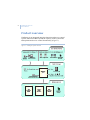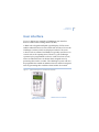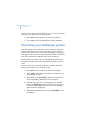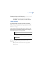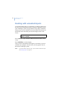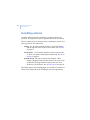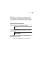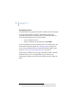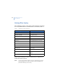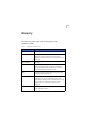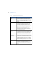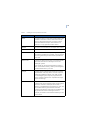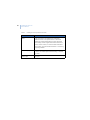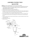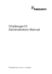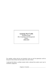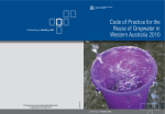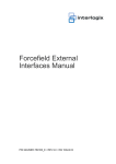
1
GE
Security
Challenger V8 & V9
User Manual
Copyright
Copyright © 2008, GE Security Pty. Ltd.. All rights reserved.
This document may not be copied or otherwise reproduced, in whole or in part,
except as specifically permitted under US and international copyright law,
without the prior written consent from GE.
Document number/revision: 1063805 A (September 2008).
Disclaimer
THE INFORMATION IN THIS DOCUMENT IS SUBJECT TO CHANGE WITHOUT
NOTICE. GE ASSUMES NO RESPONSIBILITY FOR INACCURACIES OR OMISSIONS
AND SPECIFICALLY DISCLAIMS ANY LIABILITIES, LOSSES, OR RISKS, PERSONAL OR
OTHERWISE, INCURRED AS A CONSEQUENCE, DIRECTLY OR INDIRECTLY, OF THE
USE OR APPLICATION OF ANY OF THE CONTENTS OF THIS DOCUMENT. FOR THE
LATEST DOCUMENTATION, CONTACT YOUR LOCAL SUPPLIER OR VISIT US ONLINE
AT WWW.GESECURITY.COM.
We appreciate your input about our product documentation. Please send feedback, or notify us of errors or omissions, by email to GE Security at
[email protected].
This publication may contain examples of screen captures and reports used in
daily operations. Examples may include fictitious names of individuals and
companies. Any similarity to names and addresses of actual businesses or
persons is entirely coincidental.
Trademarks
and patents
GE and the GE monogram are registered trademarks of General Electric.
Challenger product and logo are trademarks of GE Security.
Other trade names used in this document may be trademarks or registered
trademarks of the manufacturers or vendors of the respective products.
Intended use
Use this product only for the purpose it was designed for; refer to the data sheet
and user documentation. For the latest product information, contact your local
supplier or visit us online at www.gesecurity.com.au.
iii
Contents
Preface. . . . . . . . . . . . . . . . . . . . . . . . . . . . . . . . . . . . . . . . . . . . . . . . . . . . . . . v
Conventions used in this document . . . . . . . . . . . . . . . . . . . . . . . . . . . . . vi
Safety terms and symbols . . . . . . . . . . . . . . . . . . . . . . . . . . . . . . . . . . . . . . vi
Chapter 1. Introduction . . . . . . . . . . . . . . . . . . . . . . . . . . . . . . . .1
Product overview . . . . . . . . . . . . . . . . . . . . . . . . . . . . . . . . . . . . . . . . . . . . . 2
User interface . . . . . . . . . . . . . . . . . . . . . . . . . . . . . . . . . . . . . . . . . . . . . . . . 3
RAS indications . . . . . . . . . . . . . . . . . . . . . . . . . . . . . . . . . . . . . . . . . . . . . . . . 4
Chapter 2. Using Challenger . . . . . . . . . . . . . . . . . . . . . . . . . . . .7
User authentication . . . . . . . . . . . . . . . . . . . . . . . . . . . . . . . . . . . . . . . . . . . 8
Cards. . . . . . . . . . . . . . . . . . . . . . . . . . . . . . . . . . . . . . . . . . . . . . . . . . . . . . . . . . 9
PIN codes . . . . . . . . . . . . . . . . . . . . . . . . . . . . . . . . . . . . . . . . . . . . . . . . . . . . . 9
Arming your Challenger system . . . . . . . . . . . . . . . . . . . . . . . . . . . . . . . 11
Disarming your Challenger system. . . . . . . . . . . . . . . . . . . . . . . . . . . . . 12
Timed disarming . . . . . . . . . . . . . . . . . . . . . . . . . . . . . . . . . . . . . . . . . . . . . . 13
Dealing with unsealed inputs. . . . . . . . . . . . . . . . . . . . . . . . . . . . . . . . . . 14
Opening doors . . . . . . . . . . . . . . . . . . . . . . . . . . . . . . . . . . . . . . . . . . . . . . . 15
Handling alarms . . . . . . . . . . . . . . . . . . . . . . . . . . . . . . . . . . . . . . . . . . . . . 16
Alarms . . . . . . . . . . . . . . . . . . . . . . . . . . . . . . . . . . . . . . . . . . . . . . . . . . . . . . . 17
Local alarms. . . . . . . . . . . . . . . . . . . . . . . . . . . . . . . . . . . . . . . . . . . . . . . . . . 19
System alarms. . . . . . . . . . . . . . . . . . . . . . . . . . . . . . . . . . . . . . . . . . . . . . . . 20
Viewing the quick alarm history . . . . . . . . . . . . . . . . . . . . . . . . . . . . . . . 21
Using the menu . . . . . . . . . . . . . . . . . . . . . . . . . . . . . . . . . . . . . . . . . . . . . . 22
Isolating inputs . . . . . . . . . . . . . . . . . . . . . . . . . . . . . . . . . . . . . . . . . . . . . . 25
De-isolating inputs . . . . . . . . . . . . . . . . . . . . . . . . . . . . . . . . . . . . . . . . . . . 26
Glossary . . . . . . . . . . . . . . . . . . . . . . . . . . . . . . . . . . . . . . . . . . . . .27
iv
Challenger V8 & V9
User Manual
v
Preface
This is the GE Security User Manual for Challenger™ V8 and
V9 intrusion detection and access control panels. This manual is
intended primarily for Challenger system users who need to know
how to perform everyday operations using an access card or a
personal identification number (PIN) on a keypad.
This manual includes an overview of the product and detailed
instructions explaining how to:
•
•
•
•
Note:
arm and disarm your Challenger system;
isolate devices that are generating false alarms;
unlock doors (if applicable to your Challenger system);
and
respond to alarms when they occur.
The permissions assigned to you may not allow you to do
everything described in this manual. You may not be able to see all
of the User menu items described in this manual.
Depending on what you need to do, you may need to refer to the
other Challenger V8 & V9 manuals:
•
•
Refer to the Challenger V8 & V9 Administrator’s Manual
if you need additional details about using the Challenger
system.
Refer to the Challenger V8 & V9 Programming Manual
if you are an installer or administrator and you need to
know details of Challenger system programming.
This manual describes the tasks that a user should know how to
perform on a Challenger system, using a keypad or reader remote
arming station (RAS).
Note:
A qualified service person, complying with all applicable codes,
should perform all required hardware installation.
vi
Challenger V8 & V9
User Manual
Conventions used in this document
The following conventions are used in this document:
Bold
Menu items and buttons.
Italic
Emphasis of an instruction or point; special terms.
File names, path names, windows, panes, tabs,
fields, variables, and other GUI elements.
Titles of books and various documents.
Blue italic
(Electronic version.) Hyperlinks to cross-references,
related topics, and URL addresses.
Monospace
Text that displays on the computer screen.
Programming or coding sequences.
Safety terms and symbols
These terms may appear in this manual:
CAUTION:
Cautions identify conditions or practices that may
result in damage to the equipment or other property.
WARNING:
Warnings identify conditions or practices that could
result in equipment damage or serious personal injury.
Chapter 1
Introduction
This chapter provides an overview of a typical
Challenger system and some user interface devices
that you may need to operate.
In this chapter:
Product overview . . . . . . . . . . . . . . . . . . . . . . . 2
User interface . . . . . . . . . . . . . . . . . . . . . . . . . . 3
2
Challenger V8 & V9
User Manual
Product overview
Challenger is an integrated intrusion detection and access control
system. Add-on modules expand the capacity of the system and
add sophisticated access control functionality (Figure 1).
Figure 1. Challenger system overview
Chapter 1
Introduction
User interface
Figure 2 depicts two examples of Challenger user interface
devices called remote arming stations (RASs).
A RAS with a keypad and liquid crystal display (LCD) screen
enables authorised users to enter a PIN code in order to access the
Challenger’s menus, which are displayed on the LCD screen.
A device such as a Smart Card Reader is typically used for access
control such as for opening doors. However, your Challenger
system may be programmed to also use cards for alarm control,
where an authorised user can disarm their assigned areas by
presenting their card to a reader. The Challenger system can also
be programmed to enable an authorised user to arm their assigned
areas by presenting their card three times within 10 seconds.
Figure 2. Typical Challenger user interface devices (RASs)
CA1116 16-area RAS
with inbuilt card reader
TS0870 Smart Card Reader
3
4
Challenger V8 & V9
User Manual
RAS indications
RASs typically have one or more red area light-emitting diodes
(LEDs) to indicate whether their areas are armed, disarmed, or in
alarm state. Area LEDs are lit when the corresponding area is
armed, and flash to indicate that an alarm has occurred in the
area.
Note:
When an area LED on a door’s RAS is lit, the area is armed. Do not
open the door unless you can disarm the area1 or you may trigger
an alarm.
Some RAS models have additional LEDs that indicate faults and
other conditions. Refer to the particular model’s Installation
Guide for details.
A RAS with an LCD screen enables authorised users to use the
Challenger system’s menus, and displays messages about alarms
or unsealed inputs that may prevent an area from being armed.
The RAS’s beeper provides a number of indications:
•
•
•
•
1.
A short beep indicates that a valid card is presented at a
reader or a key is pressed on a keypad.
Seven short beeps indicates that a PIN or card is not valid
at the particular RAS or at the particular time, or that the
area you are attempting to arm has an input that is
unsealed or in alarm.
A continuous tone indicates that an input test is being
performed.
Continuous beeping indicates that one or more inputs are
in local alarm.
Your Challenger system may be programmed to shunt (ignore) certain
inputs when a door is opened in order to allow temporary access when
armed. Consult your installation company if in doubt.
Chapter 1
Introduction
•
Your Challenger system may be programmed so that the
RAS beeps whilst an entry timer, exit timer, or warning
timer is running.
If you need to use the keypad, refer to the Challenger V8 & V9
Administrator’s Manual for detailed instructions.
A RAS’s LCD screen displays messages about the state of the
Challenger system and to help navigate the User menu (subject to
permissions). The display might also show information you have
entered on the keypad.
Figure 3. Default LCD welcome screen
There Are No Alarms In This Area
Code:
The welcome screen indicates that the Challenger system is ready
to receive commands. The top line is a configurable message,
such as the default “There Are No Alarms In This Area”.
Alternatively, the system may be programmed to display the time
and date, or other text such as the company name.
A blank top line indicates that an alarm has been generated by
one or more inputs. “Local Alarm” indicates that one or more
local alarms are active (see Local alarms on page 19).
The bottom line displays “Code:”, which indicates that the
Challenger system is ready to accept a PIN code.
The top line of the display shows system information and other
messages. If the message is too long to fit on the top line, you
may have the following options for seeing additional characters:
Scrolling. Also called rotation, scrolling displays the text in
a scrolling ‘banner’ style.
5
6
Challenger V8 & V9
User Manual
Scanning. You may see a “1-Scan” option displayed on the
bottom line. Press the [1] key to shift the text to the left.
The bottom line of the LCD screen contains instructions and
indicates the characters you enter on the keypad (except for PIN
codes, which are shown as ‘*’ characters).
Displaying input names
Inputs are identified by a number2 and (optionally) a name
programmed by the installer. The name is useful to determine the
location of an input that is unsealed or in alarm.
Your Challenger system may be programmed to display input
names along with their numbers (Figure 4).
Figure 4. Input names displayed
Unsealed On 6, Front Door
NEXT or ENTER
Alternatively, your system might be programmed to display a list
of input numbers (Figure 5).
Figure 5. Input numbers displayed
Unsealed On 6, 7, 9.
NEXT or ENTER
In this case, enter an input number and press [ENTER] to display
the input’s name.
2.
An input number higher than 256 indicates that the input is connected
to a linked Challenger V9 panel.
Chapter 2
Using Challenger
This chapter describes how to perform everyday
operations using an access card or a personal
identification number (PIN) on a Challenger system
keypad.
In this chapter:
User authentication. . . . . . . . . . . . . . . . . . . . . . 8
Arming your Challenger system . . . . . . . . . . . 11
Disarming your Challenger system. . . . . . . . . 12
Dealing with unsealed inputs . . . . . . . . . . . . . 14
Opening doors. . . . . . . . . . . . . . . . . . . . . . . . . 15
Handling alarms . . . . . . . . . . . . . . . . . . . . . . . 16
Viewing the quick alarm history . . . . . . . . . . . 21
Using the menu . . . . . . . . . . . . . . . . . . . . . . . . 22
Isolating inputs . . . . . . . . . . . . . . . . . . . . . . . . 25
De-isolating inputs . . . . . . . . . . . . . . . . . . . . . 26
8
Challenger V8 & V9
User Manual
User authentication
Before you can use the Challenger system (for example, to
unlock a door) you must first identify yourself as a user in the
particular system. This is called authentication, and can take
various forms, such as:
•
•
•
•
•
By entering a personal identity number (PIN code) on a
RAS keypad.
By presenting a card or key fob to a reader-equipped
RAS.
Using a wireless remote device, such as a transmitter,
read by appropriate hardware.
Allowing appropriate hardware to read biometric factors,
such as a fingerprint.
A combination of the above.
In addition to having a record in the Challenger system’s
database, your assigned alarm group must permit the operation.
For example, authentication will fail if you do not have access to
the particular door at the particular time of day. If authentication
fails, the RAS beeps seven times in quick succession.
Note:
Unless otherwise noted, this manual will use the term “enter your
PIN code”, regardless of the type of authentication your Challenger
system requires.
Chapter 2
Using Challenger
Cards
Cards are typically issued to users to enable them to unlock
certain doors at certain times. Depending on how your Challenger
system is configured, cards may be used to arm and disarm
areas3:
•
•
A single swipe of a card can disarm areas and unlock the
door for you to enter.
Three swipes of the card within 10 seconds can arm areas
and unlock the door for you to exit.
PIN codes
A PIN code (or user code) is a series of four to 10 digits that
uniquely identifies you to the Challenger system. When used for
access control, your Challenger system may be programmed so
that you can use your PIN code to open a door, or you may need
to use a door code. In addition, you might have the ability to use a
duress code. These terms are explained below.
Door codes. An access control system might use a door
code, which is a shortened version of a PIN code (but still
must be at least four digits). For example, if the number
of alarm code prefix digits is two, then the minimum
length of the PIN code becomes six instead of four. If a
PIN code is 123456, then the door code is 3456 because
the two prefix digits are removed.
Duress codes. Your system might be configured for keypad
duress, which allows you to signal a duress condition (for
example, a holdup) by entering a special duress code on a
keypad instead of your PIN or door code.
3.
Only areas that are assigned to both the user and the reader can be
armed or disarmed.
9
10
Challenger V8 & V9
User Manual
When a duress code is used, the Challenger system operates as if
the normal PIN code was entered (for example, it opens the door),
and does the following:
•
•
Reports a (silent) duress alarm to the remote monitoring
company.
Displays the characters “...,” on the LCD screen.
The special duress code is the user’s PIN+1 (last digit only). For
example, if your PIN code is 8914 then the duress code is 8915. If
your PIN code is 8919, then the duress code is 8910 because only
the last digit is affected.
To reset (cancel) the duress alarm, enter your usual PIN code.
Note:
If duress was activated under conditions which are no longer valid
(false alarm), and it has been reset, it is important that you contact
your monitoring company to ensure that no further action is taken
by them.
Chapter 2
Using Challenger
Arming your Challenger system
You must arm your Challenger system in order to activate
intrusion detection when you leave the premises. Once you have
armed the system, you must leave the area within a preset exit
time to avoid setting off the alarm.
Inputs in the areas you need to arm may first need to be sealed
(for example, doors and windows must be closed). If the RAS
sounds seven quick beeps and displays the word “unsealed”, you
will need to seal or isolate the input (see Dealing with unsealed
inputs on page 14).
The arming procedure will vary depending on whether your
assigned alarm group has been programmed to display a list of
areas.
If areas are listed, use the following steps to arm all unarmed
areas that are assigned to your alarm group.
1. Press nnnn (where nnnn are your PIN code digits).
2. Press [ON]. Any disarmed areas that are assigned to your
alarm group are listed.
3. Enter 0 and press [ENTER] to arm all disarmed areas.
The corresponding RAS area LEDs illuminate.
4. Alternatively, enter one of the displayed area numbers
and press [ENTER] to arm only that area. Repeat as
needed to arm additional areas. The corresponding RAS
area LEDs illuminate.
5. When finished arming areas, press [ENTER] to exit the
display.
11
12
Challenger V8 & V9
User Manual
If areas are not listed, use the following steps to arm all unarmed
areas that are assigned to your alarm group.
1. Press nnnn (where nnnn are your PIN code digits).
2. Press [ON]. The corresponding area LEDs illuminate.
Disarming your Challenger system
You must disarm your Challenger system in order to deactivate
intrusion detection so that you can enter the premises without
setting off the alarm. If you enter before disarming, you typically
have a preset entry time to avoid setting off the alarm. The RAS’s
area LEDs illuminate to indicate which areas are armed.
The disarming procedure will vary depending on whether your
assigned alarm group has been programmed to display a list of
areas.
If areas are listed, use the following steps to disarm all armed
areas that are assigned to your alarm group.
1. Press nnnn (where nnnn are your PIN code digits).
2. Press [OFF]. Any armed areas that are assigned to your
alarm group are listed.
3. Enter 0 and press [ENTER] to disarm all armed areas.
The corresponding RAS area LEDs extinguish.
4. Alternatively, enter one of the displayed area numbers
and press [ENTER] to disarm only that area. Repeat as
needed to disarm additional areas. The corresponding
RAS area LEDs extinguish.
5. When finished disarming areas, press [ENTER] to exit
the display.
Chapter 2
Using Challenger
If areas are not listed, use the following steps to disarm all armed
areas that are assigned to your alarm group.
1. Press nnnn (where nnnn are your PIN code digits).
2. Press [OFF]. The corresponding area LEDs extinguish.
Timed disarming
The alarm group that is assigned to your PIN code might be
programmed to temporarily disarm the area that you are going to
enter, and then automatically rearm the area after a time so that
you don’t need to remember to arm it. This is done via a concept
called a user category.
A user category is programmed with a name to identify the type
of user for which it is intended (for example, ‘Guard’). When a
user category is in effect (the user category timer is running), the
LCD screen displays the user category name.
Guard,
Code:
When the user category timer expires, the RAS starts beeping for
the warning time, and the LCD screen displays ‘ending’.
Guard, ending
Code:
When the warning timer expires, the area will automatically arm.
To avoid setting off an alarm, you need to do one of the
following:
•
•
Enter your PIN code to reset the user category timer.
Vacate the area.
13
14
Challenger V8 & V9
User Manual
Dealing with unsealed inputs
An unsealed input (such as an open door or window contact) can
prevent an area from being armed or disarmed, depending on how
your Challenger system is programmed. If any input is unsealed
when you try to arm or disarm an area, the RAS will sound seven
quick beeps and will identify the unsealed inputs on the LCD
screen.
Unsealed On 6, Front Door
NEXT or ENTER
Press [NEXT] or [*] to display additional unsealed input names,
if any.
Press [ENTER] to exit the display.
After you have determined which inputs are unsealed, you must
seal them (for example, close the door), and try again to arm or
disarm the Challenger system.
Note:
If you are unable to seal an input, you will need to isolate the input.
See Isolating inputs on page 25.
Chapter 2
Using Challenger
Opening doors
Your Challenger system might be used for access control, where
you can enter your PIN code (or your door code, if used) to
unlock a door.
Use the following steps to unlock a door and to enter or exit a
disarmed area.
1. Press nnnn (where nnnn are your PIN code or door code
digits, as applicable to your system).
2. Press [ENTER].
Refer to the Challenger V8 & V9 Administrator’s Manual for
other options, such as opening doors in armed areas.
15
16
Challenger V8 & V9
User Manual
Handling alarms
An alarm indicates that the Challenger system has detected a
problem, for example if a door is opened when its area is armed.
There are three types of alarms used in a Challenger system, and
each type has its own indication:
Alarm. For an input in alarm, the RAS’s area LED flashes,
and the top line of the LCD screen is blank. See Alarms
on page 17.
Local alarm. “Local Alarm” displays on the top line of the
LCD screen, and the RAS beeps continuously. See Local
alarms on page 19.
System alarm. The type of alarm (for example, “DGP
tamper”) displays on the top line of the LCD screen. Your
system may be programmed to operate the siren and
strobe for system alarms. See System alarms on page 20.
The alarm signal (siren, flashing light, etc.) and the circumstances
which cause it depend on the Challenger system programming.
Chapter 2
Using Challenger
Alarms
When an alarm is generated there can be a number of inputs in
alarm simultaneously. It’s important to know which inputs are
causing the alarm in order to deal with them. Inputs are identified
by a number in the range 1 to 255, and a name programmed by
the installer.
Determine the source of the alarm
When there is an alarm, the corresponding area LED on the RAS
flashes red and the LCD screen displays the following:
Code:
Press [ENTER] [ENTER] to see which inputs are in alarm. If
you see only numbers and no names, refer to Displaying input
names on page 6.
Alarm on A1,Front Door PIR
NEXT or ENTER
Press [NEXT] or [*] to update the list of inputs and display the
next inputs in the list (if any).
Note:
Inputs in alarm are displayed with an A in front of the number.
Inputs in tamper are displayed with a T in front of the number.
17
18
Challenger V8 & V9
User Manual
Resetting alarms
An authorised user typically must enter a PIN code at the keypad
to reset (acknowledge) an alarm4. Depending on how your
assigned alarm group is programmed, you would typically use
one of the following ways to reset the alarm:
•
•
Arm or disarm the area.
Enter your PIN code and then press [ENTER].
If you are unable to reset an alarm because of a faulty input, you
will need to isolate the input (see Isolating inputs on page 25).
If you reset an alarm before you determine which input it came
from, see Viewing the quick alarm history on page 21.
If the alarm conditions are no longer valid (false alarm), and the
alarm has been reset, it is important that you contact your
monitoring company to ensure that no further action is taken by
them.
4.
Individual RASs may be programmed to enable authorised users to
reset alarms without code by pressing [ENTER] [ENTER] [0] [ENTER].
Chapter 2
Using Challenger
Local alarms
A local alarm is one which occurs when an area is occupied
(disarmed) and is therefore transmitted only within the building
and not relayed to a remote monitoring station (for example, a
fire door has been opened).
Responding to a local alarm
When there is a local alarm, the corresponding area LED on the
RAS flashes red, and the RAS beeps continuously. The LCD
screen displays the following:
Local Alarm
Code:
Press [ENTER] [ENTER] to see which inputs are in alarm. If
you see only numbers and no names, refer to Displaying input
names on page 6.
Local Alarm on A3,Rear Fire Door 1
NEXT or ENTER
Note:
Inputs in alarm are displayed with an A in front of the number.
Press [NEXT] or [*] to update the list of inputs and display the
next inputs in the list (if any). There may be more than one input
in alarm, and if you reset without checking you might not know
about the additional inputs.
Press [0] [ENTER] to reset all local alarms and to exit the
display.
Note:
Your Challenger system may be programmed to require an
authorised user to enter their PIN code to reset certain local
alarms.
19
20
Challenger V8 & V9
User Manual
Correct the condition that caused the local alarm (for example,
close the fire door) before the local alarm reminder time expires,
or the input will re-alarm. If a re-alarm occurs, the letter A
preceding the input number will not be shown.
System alarms
System alarms indicate that a Challenger device (control panel,
DGP, or RAS) has been tampered with, has stopped
communicating, or has detected a fault condition such as mains
fail, low battery, fuse fail, etc.
Your Challenger system may be programmed so that system
alarms automatically reset and generate restoral messages when
the alarm condition is no longer present. For example, a mains
fail alarm is cancelled when power is restored.
Alternatively, your Challenger system may be programmed so
that system alarms latch. This means that a system alarm does not
automatically reset, and a valid PIN code (that is authorised to
reset system alarms) must be entered. The procedure to identify
and reset latching system alarms is the same as the procedure
described for Alarms on page 17.
Chapter 2
Using Challenger
Viewing the quick alarm history
Quick alarm history is a simple way to determine the location of
the input that caused an alarm.
To display the quick alarm history, there must be no active
alarms. The LCD screen must show the default message on the
top line and the word “Code” on the bottom line.
There Are No Alarms In This Area
Code:
Press [ENTER] [ENTER] to display the quick alarm history.
*13:23 31/10 LOCAL ALARM Input 1 Fire D>
1-Scan, 0-Exit
The LCD screen shows the most recent alarm details:
•
•
•
•
The time the alarm occurred as hour and minutes
(HH:MM).
The date the alarm occurred as day and month (DD:MM).
The type or alarm.
The input number and name of the alarm.
Press [ENTER] to display earlier alarms.
Press [NEXT] to display later alarms.
Press [1] to shift the text displayed on the top line to reveal any
additional characters.
Press [0] to exit quick alarm history.
21
22
Challenger V8 & V9
User Manual
Using the menu
The Challenger system’s User menu (main menu) has 24 options
for use by authorised users, administrators, or installers (Table 1).
Table 1.
Challenger user menu (top level)
User menu option
1. Panel Status
13. Start Auto Access Test
2. Input Unsealed
14. Program Users
3. Input In Alarm
15. Time and Date
4. Input Isolated
16. Isolate/Deisolate RAS/DGP
5. History
17. Enable/Disable Service Tech
6. Test Report
18. Reset Cameras
7. Service Menu
19. Install Menu
8. Film Counters
20. Door and Floor Groups
9. Input Text
21. Holidays
10. Isolate
22. Open Door
11. Deisolate
23. Unlock, Lock, Disable and
Enable
12. Test Input
24. Print History
Refer to the Challenger V8 & V9 Administrator’s Manual for
details about these options.
Note:
A menu option will be visible to you only if allowed by the alarm
group assigned to you and to the alarm group assigned to the
particular RAS that you are using.
Chapter 2
Using Challenger
Use the following steps to access the User menu when the “Code”
prompt is displayed on the bottom line of the LCD screen.
There Are No Alarms In This Area
Code:
1. Press [MENU*].
To Access Menu Enter Code
Code:
2. Enter nnnn (where nnnn is your PIN code), and press
[ENTER] to display the “Menu” prompt.
“0”-Exit “ENTER” -Down “*” -Up
0-Exit, Menu:
3. From the “Menu” prompt, you can now select the User
menu option you need (see Table 1 on page 22).
4. When finished, press [0] [ENTER] to exit the menu.
Note:
After a few minutes of inaction, the Challenger system will
automatically exit the menu and return to the “Code” prompt. GE
recommends that you press [0] [ENTER] to exit the menu to
prevent unauthorised use (which will be logged against your PIN
code).
The following keys are used to move between user menu options:
•
•
•
•
Press [ENTER] to scroll forward one menu option.
Press [MENU*] to scroll backward one menu option.
Enter the menu number and press [ENTER] to jump
directly to a menu.
Enter 0 and press [ENTER] or press [CLEAR] to exit
the menu.
23
24
Challenger V8 & V9
User Manual
To program a value, such as a number or amount, enter the value
and press [ENTER]. The information will be saved and the
display will show the next option.
To program a YES/NO option, press [ENTER] to accept the
display or press [MENU*] to toggle between YES and NO. Enter
0 to skip options.
Chapter 2
Using Challenger
Isolating inputs
You may need to isolate an input to prevent false alarms (possibly
due to a faulty input device). Isolating the input excludes it from
functioning as part of the intrusion detection system.
If an input is in an alarm state, then isolating it resets the alarm.
After the problem is resolved the input must be de-isolated (see
De-isolating inputs on page 26).
A faulty input is typically unsealed, and cannot be sealed. You
can also isolate sealed inputs if you know the input number.
From the “Menu” prompt, use the following steps to isolate an
input.
1. Enter [10] and press [ENTER]. The LCD screen displays
either unsealed inputs or the message “All Inputs are
Sealed”.
Unsealed on 1,Front door
Input No:
2. If the LCD screen indicates that there is at least one
unsealed input, press [NEXT] or [*] to display additional
unsealed inputs (if any).
3. Enter the number of an unsealed (or a sealed) input and
press [ENTER] to isolate that input.
4. Repeat the previous step for any additional inputs you
need to isolate.
5. When finished, press [ENTER] to exit this menu option.
25
26
Challenger V8 & V9
User Manual
De-isolating inputs
An input may have been isolated to prevent false alarms (possibly
due to a faulty input device). Isolating the input excludes it from
functioning as part of the intrusion detection system (see
Isolating inputs on page 25). After the problem is resolved the
input must be de-isolated.
Note:
Do not de-isolate the input before checking the circumstances, as
de-isolating an unsealed input may cause an alarm.
From the “Menu” prompt, use the following steps to de-isolate an
input.
1. Enter [11] and press [ENTER]. The LCD screen displays
a list of isolated inputs or the message “All Inputs are DeIsolated”. Isolated inputs that are unsealed are indicated
with a ‘u’ in front of the input number.
Isolated on u3, Rear door
DeIsolate:
2. If the LCD screen indicates that there is at least one
isolated input, press [NEXT] or [*] to display additional
isolated inputs (if any).
3. Enter the number of an isolated input and press
[ENTER] to de-isolate that input.
4. Repeat the previous step for any additional inputs you
need to de-isolate.
5. When finished, press [ENTER] to exit this menu option.
27
Glossary
This section explains some terms as they apply to your
Challenger system.
Table 2.
Challenger terms explained
Term
Definition
Access
The state of an area when it’s disarmed.
Access control
Control of entry to, or exit from, a security area. The
Challenger system typically controls access by
allowing only authorised users to unlock a door or to
enter a lift.
Acknowledge
See reset.
Alarm
The state of a intrusion detection system when a
input is unsealed and the condition of the area is
such that state should be signalled, for example, a
door is opened when its area is armed.
Area
A logical grouping of input devices that are armed
and disarmed simultaneously.
Card
A portable device (card or fob) that holds information
to identify a user to the Challenger system. The
information to identify a user can be stored in a chip
(smart card), on a magnetic strip, a bar-code, a
Wiegand card, or in biometric data such as a
fingerprint.
DGP
Data Gathering Panel. A DGP expands the capacity
of the Challenger system.
28
Challenger V8 & V9
User Manual
Table 2.
Challenger terms explained (continued)
Term
Definition
Input
An electrical signal from a security device (input
device) to the intrusion detection system. Each input
device is identified by a number and name, for
example, “14. Reception Holdup Button”, or “6. Fire
Exit Door”.
Intrusion detection
Electrical detection devices (called inputs) are
connected to the Challenger panel. Based on the
type of device and whether the device’s location
(called area) is armed or disarmed, the device
triggers an alarm when something activates it. For
example, the device might be a reed switch that
detects a door being opened when the area is
armed. An alarm typically triggers a siren and
flashing light to operate, and sends a message to a
remote monitoring company.
Isolate
The input device is inhibited from indicating sealed
or unsealed status. It is excluded from functioning as
part of the system. If a input device is defective or
there is a reason it cannot be sealed, then it may
need to be isolated before the area can be armed.
Local alarm
An alarm which is transmitted only within a building,
and occurs when an area is disarmed. The
circumstances which cause a local alarm can be
checked and rectified by personnel on site and it is
therefore unnecessary for the alarm to be relayed to
a remote monitoring company.
RAS
Remote arming station. A user interface device such
as a keypad or card reader that enables a user to
authenticate their identity and perform some
operation such as unlocking a door or arming the
system.
29
Table 2.
Challenger terms explained (continued)
Term
Definition
Reset
To cancel an alarm. A users who is authorised to arm
and disarm the area in alarm, resets the alarm by
arming or disarming the area. The input in alarm
must be sealed (for example, close the door) or
isolated, or it may generate another alarm.
Sealed
The input is not activated, for example, door closed.
Secure
The state of an area when it’s armed.
Shunt
A process that inhibits an input from generating an
alarm when unsealed. For example, a shunt stops a
door from generating an alarm when opened for a
short time.
Smart card
An electronic device in the form of a card or key fob
that holds information to identify a user to the
Challenger system.
Smart cards can be programmed with a unique 4billion combination security code to protect against
unauthorised access to your site.
Tamper
A tamper alarm indicates that someone may have
tampered with a security device, such as a input or
Challenger hardware (cabinet, siren, DGP, or RAS).
Your Challenger system may be programmed to
monitor tamper indications on input devices (input
tamper monitoring).
Unsealed
A input device is unsealed (active) when it detects a
condition that may be used to trigger an alarm when
the area is armed. For example, a front door’s
detector is unsealed each time the door is open, but
the unsealed state is ignored unless the area
containing the detector is armed. An unsealed input
may prevent the area from being armed. For
example, you need to close the door before you can
arm the area.
30
Challenger V8 & V9
User Manual
Table 2.
Challenger terms explained (continued)
Term
Definition
User
A user is a person recorded in the Challenger
database. Users can operate some or all of the
Challenger system, depending on their assigned
functionality. A user might be someone with an ID
card to unlock a door, or someone with extended
functionality, such as an administrator or a security
company installer.
User category
A user category can be assigned to an alarm group
to restrict or enable special functionality or access
by a user.
Zone input
See input