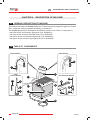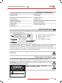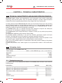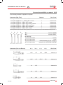
1
lide
euc
User Manual
Plaster drill
IT
FR
DE
EN
ES
MAINTENANCE AND USE MANUAL
EN
GENERAL INDEX
CH. 1
INTRODUCTION
Pag. 111
Pag. 112
1.1
1.2
How to read and use the manual
Terms and symbols used
GENERAL INFORMATIONS
Pag.
Pag.
Pag.
Pag.
113
113
113
114
2.1
2.2
2.3
2.4
DESCRIPTION OF MACHINE
Pag.
Pag.
Pag.
Pag.
Pag.
116
116
117
117
117
3.1
3.2
3.2.1
3.3
3.3.1
118
118
118
119
119
4.1
4.2
4.2.1
4.2.2
4.2.3
122
122
123
123
5.1
5.2
5.3
5.4
e u c lid e
124
124
124
125
125
125
126
126
127
128
129
130
130
6.1
6.2
6.2.1
6.3
6.3.1
6.4
6.5
6.5.1
6.5.2
6.6
6.7
6.8
6.9
CH. 5
General instructions
Packing and unpacking
Transport and handling
Elimination / Dismantling
INSTALLATION AND FIRST-TIME USE
Pag.
Pag.
Pag.
Pag.
Pag.
Pag.
Pag.
Pag.
Pag.
Pag.
Pag.
Pag.
Pag.
CH. 4
The most important technical particulars and operating start
Technical Data
Standard accessories
Accessories available on request
Weight and overall dimensions
TRANSPORT AND MOUNTING
Pag.
Pag.
Pag.
Pag.
CH. 3
General description of machine
Table of components
Description of components
Identification data
Danger signs on the machine
TECHNICAL CHARACTERISTICS
Pag.
Pag.
Pag.
Pag.
Pag.
CH. 2
Responsibilities
Warranty: general instruction
Authorized personnel
General safety warnings
CH. 6
Warnings and precautions
Permitted ambient conditions
Aspiration
Required work space
Worktops
Connecting up to the power supply
Assembling the bit
Pincer lock system
Fixed locking system
First-time use
Adjusting drilling depth
Purpose of the machine
Improper use / forbidden use
109 of 176
EN
CH. 7
USING THE MACHINE
Pag.
Pag.
Pag.
Pag.
Pag.
Pag.
131
131
131
132
132
133
7.1
7.2
7.3
7.4
7.5
7.6
Warning
Safety system
Preparing the model
Using the plaster drill: drilling the model
Completing the model
Residual risk
CH. 8
MAINTENANCE
Pag.
Pag.
Pag.
Pag.
Pag.
134
134
135
135
135
8.1
8.2
8.3
8.4
8.5
Cleaning
Routine maintenance
Unscheduled maintenance
Restarting after a long period of inactivity
Requesting technical assistance
CH. 9
TROUBLESHOOTING
Pag. 136
Pag. 136
MAINTENANCE AND USE MANUAL
9.1
9.2
Warning
Problems, causes and remedies
A.1
A.2
A.3
A.4
A.5
CE Declaration of conformity
Warranty certificate and identification form
Maintenance and repair worksheet
Authorized service partners
Notes
APPENDICES
Pag.
Pag.
Pag.
Pag.
Pag.
138
139
140
141
141
110 of 176
eu clid e
MAINTENANCE AND USE MANUAL
EN
CHAPTER 1: INTRODUCTION
HOW TO READ AND USE THIS MANUAL
1.1
This Use and Maintenance Manual provides information on the utilisation, installation and
maintenance of the euclide plaster drill manufactured by Zhermack S.p.A.
• The euclide plaster drill must be used in accordance with the instructions in this manual: it is
therefore recommended that you read it carefully prior to installation and start-up. Make sure
that you read the entire manual and pay particular attention to messages written in bold type or
items highlighted by boxes and/or symbols: the symbols are designed to highlight situations
involving danger or requiring caution (see paragraph 1.2).
• Observance of standards and regulations shown in this manual will ensure that the machine
is used properly and that maintenance work is carried out safely.
• This Use and Maintenance Manual is an integral part of the machine: it should therefore be
kept together with the eqiuipment so that it can be consulted as and when necessary (keep the
booklet in a secure dry place away from sunlight, atmospheric agents, etc.). It must be available
for consultation throughout the working life of the plaster drill even when the machine is sold or
finally dismantled.
• It is recommended that you keep this manual constantly updated by integrating any amendments,
additions or modifications made by the Manufacturer. Any notes or comments should be made
on the blank pages at the rear of the booklet (see Appendices: Note).
• Use the manual properly so that it is not damaged in any way.
• Do not remove, tear or write on any part of the pages.
• If the manual is lost or damaged and its contents become illegible you can request a
replacement copy from the Manufacturer.
The purpose of this Use and Maintenance Manual is to provide users with information on how
to operate the plaster drill properly. The manual contains all the information needed to use the
device as intended: in particular the manual includes instructions and information on the
following:
•
•
•
•
•
Correct plaster drill installation;
Detailed description of how the plaster drill works and its components;
Initial start-up;
Scheduled maintenance;
Basic Safety and Accident Prevention info.
This manual contains nine chapters each of which covers a specific argument.
The appendices at the rear of the manual are a useful complement to these chapters.
e u c lid e
111 of 176
EN
1.2
MAINTENANCE AND USE MANUAL
TERMINOLOGY AND SYMBOLS
It is important that you understand the following symbols and their significance as they
highlight important information such as critical situations, practical advice, or straightforward
information.
If you have any doubts as to the significance of a symbol always consult this page.
• Tasks for which failure to observe instructions or tampering with machine parts may put
personnel in serious danger are highlighted by the symbol:
DANGER!
This symbol refers to safety standards which must be observed at all times in order to
protect both workers and machine.
• Critical situations concerning dangerous areas or tasks in which failure to observe the
instructions may render the warranty null and void, or cause damage to machine, connected
components or the surrounding area, are highlighted by the symbol:
WARNING!
This symbol refers to safety standards which must be observed carefully in order to
guarantee your safety, other people's safety and prevent damage to the machine.
• Any work that fails to comply with instructions in this manual, or any tampering which might
automatically render the warranty null and void, is highlighted by the following symbol:
FORBIDDEN!
This symbol refers to actions which must never be carried out (i.e. forbidden
actions).
• Any general information and/or advice which may be useful at any time is highlighted by the
following symbol:
NOTE!
This symbol highlights information and/or useful advice.
112 of 176
eu clid e
MAINTENANCE AND USE MANUAL
EN
CHAPTER 2: GENERAL INFORMATIONS
RESPONSABILITY
2.1
Failure to observe the instructions in this Use and Maintenance Manual exonerates the
Manufacturer from any liability whatsoever.
For any matters not covered by this manual or about which you have any doubts please contact
the Manufacturer directly:
Zhermack S.p.A.
Via Bovazecchino, 100
45021 Badia Polesine • RO • Italy
Tel. +39 0425 597 611 • Fax +39 0425 53 596
http://www.zhermack.com
e-mail: [email protected]
If plaster drill maintenance work fails to comply with instructions or is done in such a way as to
compromise machine integrity or modify its characteristics Zhermack S.p.A. shall be
exonerated from any liability as regards worker safety and/or machine performance.
WARRANTY: GENERAL INSTRUCTION
2.2
Included in the Appendices to this Use and Maintenance Manual you will find the Warranty
certificate and the ID Form which must be filled out in full.
In general the Warranty is rendered null and void by the following:
• Improper machine use.
• Incorrect installation.
• Serious negligence of maintenance schedules.
• Modifications to or work on the machine which has not been authorised by the Manufacturer
(especially on safety devices).
• Use of non-original spare parts.
Zhermack S.p.A. cannot, as of this moment, be held liable if the machine is
modified or tampered with without prior written consent from the Manufacturer.
Consequently, any repairs made by unauthorised personnel, use of non-original
spare parts or failure to comply with the installation standards specified in this
manual shall immediately render the Warranty null and void.
AUTHORIZED PERSONNEL
2.3
Personnel may be divided into the following categories:
• Operator-user:
Person trained to use the plaster drill. He/she may carry out all the tasks needed to operate the
machine: these tasks include starting/stopping the machine, carrying out routine inspections
and any other tasks linked to everyday machine use.
e u c lid e
113 of 176
EN
MAINTENANCE AND USE MANUAL
The operator-user must only use the machine when it is fully assembled and the
safety devices are working properly as described in this manual.
Before using this machine or carrying out any work on it, the operator must
read the entire contents of this manual. This manual has been drawn up to
provide the user with essential information on rational, safe utilisation of the
machine. The user must comply with the information given at all times.
Furthermore, the user must use the work sheets enclosed with this manual so
as to keep a record of maintenance/component replacement work as well as
make notes on any machine malfunctions.
• Zhermack S.p.A. authorised maintenance technician:
Person authorised to carry out work on the machine under all operating conditions and all safety
levels. He/she is also authorised to carry out any mechanical or electrical repairs/adjustments,
scheduled maintenance and any component replacement work.
2.4
GENERAL SAFETY REGULATIONS
The operator must read the advice and warnings given below and comply with such regulations
at all times: doing so will ensure safe, long-lasting machine performance:
• Do not allow untrained personnel to use this machine.
• Ensure that the work area is properly prepared: it must be free from obstacles, clean and
properly illuminated.
• Take measures to ensure that you are not distracted when using the machine.
• In the event of a malfunction follow the advice given in this manual: if you have any doubts
shut down the machine and contact your Authorised Service Centre immediately.
• Never use a malfunctioning machine and always inform the Maintenance Manager of any
faults.
• Do not open compartments containing electrical parts.
• Do not replace the power lead or tamper with the supplied plug.
• It is forbidden to use the machine on items other than those for which it has been specifically
designed.
• Before doing any cleaning, routine and/or unscheduled maintenance work make sure that the
machine has been unplugged from the mains socket.
• Make sure that there are no foreign objects inside the work area as these could damage the
machine and/or injure personnel.
• Do not use petrol or flammable solvents as detergents; use only non-flammable, non-corrosive,
and non-toxic substances (see paragraph 8 .1).
Zhermack S.p.A. cannot be held liable for any damage to persons or objects
caused by incorrect maintenance carried out by unqualified personnel or
maintenance work that does not comply with the instructions in this manual.
Zhermack S.p.A. is, as of this moment, exonerated from any liability concerning
injury to persons or damage to objects that may result from using this
machine in a way other than that described in this manual.
114 of 176
eu clid e
MAINTENANCE AND USE MANUAL
EN
This machine has electrical parts: therefore, in the event of a fire, no matter how
small, use only powder-type extinguishers. Never attempt to put out an
electrical fire with water.
e u c lid e
115 of 176
EN
MAINTENANCE AND USE MANUAL
CHAPTER 3: DESCRIPTION OF MACHINE
3.1
GENERAL DESCRIPTION OF MACHINE
This manual describes the euclide plaster drill. The drill has been designed to apply the “Dowel
Pins”, technique, based on parallel positioning of dowel pins.
The euclide plaster drill is available in the following versions (see “Table of components”):
• with fixed chuck and bulb-type light guide (Cod. A0200010);
• with fixed chuck and laser-type light guide (Cod. A0200020);
• with pincer chuck and bulb-type light guide (Cod. A0200030);
• with pincer chuck and laser-type light guide (Cod. A0200040).
3.2 TABLE OF COMPONENTS
LASER VERSION
BULB VERSION
11
1
FIXED
CHUCK VERSION
8
PINCER CHUCK VERSION
5
14
2
12
3
17
4
6
9
15
7
13
16
10
116 of 176
eu clid e
MAINTENANCE AND USE MANUAL
EN
Description of components 3.2.1
1. Laser system
2. Allen key n°2
3. Drill bit for fixed chuck (see section. 4.2.1)
4. Fixed chuck
5. Mobile support top
6. Hole depth regulator
7. Main switch
8. Binocular
9. Rubber mat
10. Power lead
11. Light bulb
12. Wrench n°14
13. Wrench n° 10
14. Drill bit for pincer chuck (see section 4.2.1)
15. Pincer chuck lock
16. Pincer chuck shaft
17. Bit fixing grub screw
IDENTIFICATION DATA
3.3
The machine described in this manual has an ID platelet giving information about both the
machine and the manufacturer.
A
B
D
Zhermack S.p.A.
A.
B.
C.
D.
BADIA POLESINE - ITALY
C307001 - EUCLIDE
Matr. 20000000
230 V~ 50/60 Hz 30W
Name and address of manufacturer
Machine code and model
Serial number
Power supply information
C
The euclide plaster drill has been built in compliance with the EC directives listed in the
enclosed "EC decoration of conformity". When requesting spare parts, information or
assistance from your Authorised Servicing Centre always quote the data on the ID plate.
Should the ID plate deteriorate and become illegible, even partially, order a replacement plate
from the manufacturer: remember to quote the relevant data.
Do not remove and/or the damage the plate as you must be able to read the data
at all times.
Danger signs on the machine 3.3.1
On the rear of the machine there is a label with the following symbol. It reads:
ATTENZIONE! DANGER OF AN ELECTRICAL CURRENT. DO NOT OPEN DOORS
OR REMOVE PROTECTION BEFORE YOU HAVE DISCONNECTED THE PLUG
FROM THE ELECTRICAL SOURCE
DANGER! VISIBLE LASER RADIATION. AVOID
DIRECT EYE EXPOUSURE.
DANGER
LASER
V I S I B L E L A S ER RADI ATI ON
- A V O I D D I R ECT EYE EXPOUS URE
O P T I C A L O UTPUT POWER
W A V E L E N N GHT
5 mW
5 0 mW
C L A S S I I I b LAS ER PRODUCT
e u c lid e
117 of 176
EN
MAINTENANCE AND USE MANUAL
CHAPTER 4: TECHNICAL CHARACTERISTICS
4.1
TECHNICAL CHARACTERISTICS AND MACHINE OPERATING PRINCIPLE
Zhermack S.p.A. designs and manufactures work instruments that provide cutting-edge
technology and first-rate quality. They are specially designed to provide made-to-measure
solutions that offer long-lasting performance every single day of their working life.
In making these products Zhermack S.p.A. makes use of the latest design tools, thus ensuring
that all finished machine is as functional as possible. Use of only top-quality materials and
thorough testing aimed at providing maximum user safety are an Zhermack S.p.A. constant,
making our products safe and internationally competitive.
The euclide plaster drill is a machine that has been designed to improve the dowel-pins
technique (i.e. the technique of applying removable dowel pins).
The euclide plaster drill is simple and easy to operate. It allows you to position pins precisely
as desired.
The guide light (bulb/laser) aids precision during drilling.
By providing parallel positioning of the pins the machine guarantees superb end-of-job
precision, ensuring that your work reaches its maximum potential at all times.
A vast range of drill bits, together with the depth adjustment feature, allows the operator to use
all dowel pin types, whether with smooth rounded heads or knurled heads.
Easy to use, this machine requires no maintenance other than periodic cleaning of the plaster
dust collection tray.
A rubber mat provides more stable support for the plaster/resin models on the mobile work
top.
4.2
TECHNICAL DATA
Technical data on the euclide plaster drill:
Power supply
Absorption
RPM
Protection rating IP
Noise level
230 V~ ± 10% 50/60 Hz (opp. 115 V~ ± 10% 50/60 Hz)
30 Watt
2800
IPX0
<70 dB
4.2.1 Standard accessories
In addition to this Use and Maintenance Manual, the euclide plaster drill also comes with the
following items:
COMPONENTS
Allen key n°2 (with fixed lock system)
Wrench n°14 (with pincer lock system)
Wrench n°10 (with pincer lock system)
Bit: stem Ø 3mm - drill bit 2mm
Pins
Sheaths
Position plugs
118 of 176
QUANTITY
1
1
1
1
100
100
100
ORD. CODE*
XH9900005
XI0200210
XI0200220
XR0200040
XR0202010
XR0202070
XR0202050
eu clid e
MAINTENANCE AND USE MANUAL
EN
Accessories available on request 4.2.2
The following material is supplied on request:
COMPONENT (BITE TYPE)
1-bit
1-bit
1-bit
1-bit
1-bit
1-bit
1-bit
pack
pack
pack
pack
pack
pack
pack
STEM.
STEM.
STEM.
STEM.
STEM.
STEM.
STEM.
QUANTITY
3.17 - DRILL BIT 2mm
3.17 - DRILL BIT 1.5mm
3 - DRILL BIT 2-3mm
3 - DRILL BIT 2mm T.10mm
3 - DRILL BIT 2mm Tung
3 - DRILL BIT 2.0x3mm
3 - DRILL BIT 1.5mm
ORD. CODE*
1
1
1
1
1
1
1
XR0200020
XR0200030
XR0200070
XR0200080
XR0200040
XR0200050
XR0200060
* Please quote the order code when ordering a spare part. You may order parts from your local Authorised Servicing Centre.
1.
2.
3.
4.
Øa
Øb
diameter STEM
diameter DRILL
Bit diameter:
1.
2.
3.
4.
COMPONENT (PINS
e u c lid e
FOR
EUCLIDE)
Cod.
Cod.
Cod.
Cod.
1,5 mm
2 mm
double diameter (2 mm. e 3 mm.)
conical bit for SATOPINS SYSTEM
XR0200060
XR0200040
XR0200070
XR0200050
a (mm)
b (mm)
c (mm)
d (mm)
ORD. CODE*
18,5
4,5
Ø2
Ø3,3
XR0202010
18,5
4,5
Ø1,5
Ø2
XR0202030
10
Ø2
20
Ø3
Ø2
XR0202110
10
Ø3
Ø2
XR0202130
XR0202050
119 of 176
EN
COMPONENT (PINS
FOR
COMPONENT (SHEATHS)
DOWEL)
MAINTENANCE AND USE MANUAL
a (mm)
b (mm)
c (mm)
d (mm)
ORD. CODE*
18,5
4,5
Ø1,5
Ø2
XR0203010
25
15
5
Ø2,6
XR0203030
18,5
4,5
Ø2
Ø3,3
XR0203050
21,5
5
Ø2
Ø3,3
XR0203070
26
14
4,5
Ø3,3
XR0203090
28,5
14
4,5
Ø3,3
XR0203110
a (mm)
b (mm)
c (mm)
d (mm)
14
Ø4,8
XR0202070
14
Ø3
XR0202090
ORD. CODE*
* Please quote the order code when ordering a spare part. You may order parts from your local Authorised Servicing Centre.
120 of 176
eu clid e
MAINTENANCE AND USE MANUAL
EN
Weight and overall dimensions 4.2.3
p
h
lide
euc
l
DIMENSIONS
Height (h)
Width (l)
Depth (p)
Weight when empty (without water)
e u c lid e
WITHOUT PACKING
cm.
cm.
cm.
kg.
40
20
18,5
7
WITH PACKING
cm.
cm.
cm.
kg.
50
41
36
10
121 of 176
MAINTENANCE AND USE MANUAL
EN
CHAPTER 5: TRANSPORT AND MOUNTING
5.1
WARNING
To prevent any injury to persons or damage to things always proceed with the
utmost care and attention when mounting the machine. Observe all the
precautions and instructions contained in the following paragraphs.
5.2
PACKING AND UNPACKING
All the material is thoroughly checked by the Manufacturer prior to shipment. When you
receive the goods make sure they have not been damaged during transit and that no-one has
tampered with the packaging and removed any of the parts contained therein.
Should you note any damage or missing parts please inform your Dealer and the shipping
carrier immediately: take photographs and send them on to both dealer and carrier.
The packaging, consisting of a cardboard box with internal expanded plastic padding, contains:
• the euclide plaster drill;
• the accessories (see section 4.2.1);
• this Use and Maintenance Manual.
ide
eucl
ide
eucl
ide
eucl
It is recommended that you keep the original packaging so that, if necessary,
it can be re-utilised; doing so ensures that you do not use unsuitable
packaging materials during transport and mounting which might lead to
accidental damage (see section 5.3).
122 of 176
eu clid e
MAINTENANCE AND USE MANUAL
EN
TRANSPORT AND MOUNTING
5.3
If it is necessary to move the machine, you must:
1. Dis-connect the machine from the electrical system;
2. Grip the machine from the bottom, making sure that you always keep it vertical. Take the
weight and overall dimensions of the machine into careful consideration before moving it (see
section 4.2.3) so as to prevent the damage that might result from inobservance of size/
weight.
3. Pack the euclide plaster drill in its original box or, if this is not possible, take all the
necessary precautions to protect the machine against knocks or drops, in that the goods are
transported at the owner's risk.
Failure to observe the above exonerates the Manufacturer from any liability
concerning machine malfunction and consequently renders the Warranty
null and void.
When shipping/delivering the machine to your Authorised Servicing Centre
always enclose a copy of the purchase document and a copy of the properly
compiled ID form.
If the unit is to be transported by courier, the postal service or rail it is
recommended such shipments be insured.
ELIMINATION / DISMANTLING
5.4
When disposing of the packaging materials the user must comply with the standards in force
in his/her country regarding the following materials:
• Wood/paper: non-polluting materials, but must be recycled properly.
• Polystyrene/plastic: pollutants which must not be burnt (toxic fumes) nor dispersed into the
environment, but disposed of in compliance with the standards in force in the country of use.
If the machine is to be dismantled the user must, in compliance with EC directives and the laws
in force in the country of use, effect elimination and recycling of the following materials:
• Plastic and glass parts, insulated electrical wiring, rubber parts.
• There are no toxic or corrosive parts.
This product must not be disposed of as household waste but rather, when
no longer used, must be collected separately according to EC Directive
2002/96.
e u c lid e
123 of 176
EN
MAINTENANCE AND USE MANUAL
CHAPTER 6: INSTALLATION AND FIRST-TIME USE
6.1
WARNINGS AND PRECAUTIONS
Before proceeding with installation make sure that all relevant safety conditions prevail and
follow the instructions below carefully.
So as to provide greater clarity the numbers given in the diagrams in this
chapter correspond exactly to the numbering in the Components Table
(Ch. 3).
6.2
PERMITTED AMBIENT CONDITIONS
Unless stated otherwise at the time of order the machine will be configured to operate properly
under the following ambient conditions:
Place of Use
Altitude
Working temperature
Humidity
Indoors
Up to 2000 m
From 5°C to 40°C
Max 80%
Ambient conditions other than those listed above may cause malfunctions or sudden
breakdowns. Lighting in the installation area must be sufficient to provide good visibility at every
single point on the machine.
More specifically, luminosity must not be less than 200 lux, lighting must be as uniform as
possible and there must be no reflected light as this could dazzle the operator.
The machine must not be used in workplaces having an atmosphere which is
explosive and/or at risk of fire as it has not been designed for use in such areas.
Nevertheless, should a fire accidentally break out follow the procedure described
in paragraph 2.4.
Work area lighting is an important factor in both personnel safety and the
ultimate quality of the work being done. In Italy lighting must comply with a
Ministerial Decree Law that clearly defines minimum lighting requirements.
In other countries lighting requirements form part of the accident prevention
and workplace hygiene standards.
6.2.1 Aspiration
The euclide plaster drill requires no special aspiration device as the plaster dust or resin swarf
produced during drilling of the models is gathered in the waste collection tray.
124 of 176
eu clid e
MAINTENANCE AND USE MANUAL
EN
REQUIRED WORK SPACE
6.3
Choosing a good workplace with an appropriate amount of space available for machine installation
is an essential factor in personnel safety, the quality of the work and proper maintenance.
This zone must not only be spacious enough to allow for optimum machine operation but must
also be well illuminated, aired, not dusty and not exposed to direct sunlight. Note also that the unit
must be positioned so the connection plug can be handled/manipulated with ease.
Worktops 6.3.1
The euclide plaster drill has been
designed for operation on a rigid worktop
parallel to the floor. Suitable worktops
include service furniture (where the
operator is standing) or modelling tables
(where work is done sitting down).
All worktops must be checked for stability.
ide
eucl
CONNECTING UP TO THE POWER SUPPLY
6.4
The user must provide a power connection with relative socket near the machine installation
point. The user must also install an adequate electrical circuit breaker upstream from the socket
as well as efficacious overload/indirect contact safety devices.
Connection is effected via the safety plug (16A in compliance with European standards) at the
end of the power lead: this must be inserted in the mains socket.
When connecting check:
• that mains voltage and frequency are as indicated on the identification plate (incorrect power
supply voltage may damage the machine);
• that the mains supply has a proper, efficient earth connection.
It is forbidden to tamper with the power lead and its plug.
A proper earth connection is compulsory. Should it temporarily be
necessary to use an extension lead the latter must comply with the
standards in force in the country of use.
e u c lid e
125 of 176
EN
6.5
MAINTENANCE AND USE MANUAL
ASSEMBLING THE BIT
The euclide plaster drill is supplied without the drill bit assembled and the rubber mat without
holes. Bit assembly varies according to the type of precision chuck.
Pincer locking system (follow the
instructions in section 6.5.1, especially
Fig.2).
Fixed locking system (follow the
instructions in section 6.5.2, especially
Fig.6).
When assembling the bit make sure that the plug is disconnected from the
mains socket.
Follow the instructions below carefully.
6.5.1 Pincer lock system
Fig. 1: Remove the rubber mat (9); lower the mobile
support top (5) until the bit-holding chuck is
completely free.
lide
euc
5
9
Figure
1
12
15
13
Figure
126 of 176
Fig. 2: Lock the chuck shaft (16) with the n°10
wrench (13) and release the chuck lock (15) with the
n°14 wrench (12).
16
2
eu clid e
MAINTENANCE AND USE MANUAL
EN
Fig. 3: Insert the bit (14) in the chuck and lock it in
place by re-tightening the stay (15) with the n°14
wrench (12) (see Fig. 2).
Then release the mobile support top (5) and
reposition the rubber mat (9).
9
lide
euc
14
Figure
3
Figure
4
5
Fig. 4: To make bit assembly even easier it is
possible to remove the mobile top (5) and re-insert it
after assembling the bit.
5
When reinserting the mobile top (5), it is essential that you align the two slide
guides in their seats and check that the bit is assembled on the chuck with the
hole at the centre of the dust/swarf tray: failure to observe the above could
cause the just-inserted bit to break immediately.
Failure to observe any of the above installation instructions may lead to
malfunctions and render the warranty null and void.
Fixed locking system 6.5.2
Fig. 5 : Remove the rubber mat (9); lower the
mobile support top (5) until the bit-holding chuck is
completely free.
lide
euc
5
9
Figure
e u c lid e
5
127 of 176
EN
lide
euc
3
2
17
Figure
MAINTENANCE AND USE MANUAL
Fig. 6: Unscrew the lock grub (17) with the supplied
Allen key (2).
Insert the bit in the chuck and lock it in place (3).
Release the mobile support top (5) and reposition the
rubber mat (9) (see Fig.3).
To make bit assembly easier the mobile top (5) can
be removed and reinserted after fitting the bit (see
Fig. 4).
6
Never unscrew the three chuck grub screws which hold the chuck to the drive
shaft: doing so could put the shaft out of alignment.
6.6
FIRST-TIME USE
ide
eucl
Figure
Fig. 7: After assembling the bit properly, set the unit
down on the horizontal work top (see section 6.3.1).
7
Fig. 8: Connect the power lead (10) to the mains:
follow the instructions in section 6.4.
10
Figure
8
Fig. 9: Press the main switch (7).
7
Figure
9
128 of 176
eu clid e
MAINTENANCE AND USE MANUAL
EN
ADJUSTING DRILLING DEPTH 6.7
Fig. 10: Push the mobile support top (5) slowly
downwards so as to create a hole in the rubber mat (9).
Once the hole has been made release pressure on
the top and switch off at the main switch (see Fig. 9).
9
lide
euc
5
Figure
Fig. 11: With the unit switched off lower the mobile
top (5) as far as it will go by turning the drilling depth
adjuster (6).
Make sure that the length of bit which
protrudes from the rubber mat
corresponds to the desired drilling
depth (i.e. desired depth of hole).
The protruding length of bit can be
modified by acting on the adjuster
wheel (6).
10
5
lide
euc
6
Figure
11
Fig. 12: If, with the bit adjuster wheel (6) at its limit
stop, protrusion is still insufficient or excessive act on
the chuck to lower or raise the bit.
When you have completed adjustment of the bit
switch on at the main switch (see Fig. 9).
lide
euc
6
Figure
12
Failure to observe any of the above installation instructions may lead to
malfunctions and render the warranty null and void.
euclide
129 of 176
EN
6.8
MAINTENANCE AND USE MANUAL
PURPOSE OF THE MACHINE
The euclide plaster drill has been designed to:
• apply the “Dowel Pins” technique.
6.9
IMPROPER USE / FORBIDDEN USE
Using the machine for any purpose other than that described in section 6.6
(Purpose of the Machine) shall be considered improper and thus forbidden.
Improper use renders the Warranty null and void and Zhermack S.p.A. shall not
be liable for any damages to objects, workers or third parties.
The main reasons for which the Warranty may be rendered null and void are given in section
2.2 and in the "Warranty Certificate" enclosed with this Manual.
130 of 176
eu clid e
MAINTENANCE AND USE MANUAL
EN
CHAPTER 7: USING THE MACHINE
WARNING
7.1
To ensure that work is done in absolute safety always make sure that you
follow the described procedures with caution.
To provide greater clarity the numbers given in the diagrams in the following
paragraphs correspond exactly to the numbering in Chapter 3 in the
"Machine Description" section.
SAFETY SYSTEMS
7.2
To ensure optimum working reliability, Zhermack S.p.A. employs only top quality materials and
components for the manufacture of the machine. The machine is also thoroughly tested
before delivery.
All materials are of only the highest quality and are checked on arrival at our plant, during
storage and when they are used so as to guarantee a product that is free from damage,
deterioration and/or malfunctions.
In particular, the euclide plaster drill has an electrical safety system consisting of a
protection fuse (fitted on the rear of the machine) designed to protect both the operator and the
machine itself from any overloads.
PREPARING THE MODEL
7.3
To ensure that the euclide plaster drill performs well the model must be prepared properly.
Proceed as follows:
1. mix the modelling plaster or resin.
2. pour the prepared mix into the mould but without constructing the horseshoe-shaped
support.
3. once it has hardened eliminate the excess plaster (or resin) until you have a horseshoe- shaped
model. The model should have a base at least 1.5 mm thick.
Pay special attention to the base of the model: make sure that it is perfectly flat.
If the base is uneven/irregular in a way that stops the model resting evenly on
the top the model or bit could break during drilling.
e u c lid e
131 of 176
EN
MAINTENANCE AND USE MANUAL
USING THE PLASTER DRILL: DRILLING THE MODEL
7.4
After preparing the machine for use (see section 6.6) and preparing the model (see section
7.3), proceed as follows:
9
x
Figure
lide
euc
Fig. 13 : Switch on the plaster drill at the main switch
(see fig. 9).
Position the work model on the rubber mat (9).
Keeping it in perfect contact with the mat with both
hands, shift the model so that guide light coincides
with the point at which you wish to drill the hole.
13
Fig. 14: Pressing the mobile support top (5) slightly
downwards switches on the drill bit motor.
Increase downward pressure until the mobile support
top (5) will go no further, thus drilling a hole in the
lower part of the model.
5
Figure
14
Fig. 15: Release downward pressure on the top (5):
a pair of springs brings it back to its home position,
switching off the machine.
lide
euc
5
Figure
Repeat the procedure for each pin you wish to insert
in the model.
15
With this technique it is compulsory to insert a dowel pin or two position plugs
in the free saddles too.
7.5
COMPLETING THE MODEL
After drilling the holes with the euclide plaster drill the dowel pins must be inserted.
We recommend that you secure the pins inside the holes using liquid cyanoacrylic adhesive
(self-activating or activatable) with minimum thickness.
After securing all the pins and the position plugs, isolate the horseshoe-shaped model with
132 of 176
eu clid e
MAINTENANCE AND USE MANUAL
EN
an appropriate insulating liquid and cast the horseshoe-shaped support in plastery material.
After complete hardening of the horseshoe-shaped support, square the model (we recommend
use of the SQM) and separate the dowels (TALETE hacksaw recommended).
euclide plaster drills allow the user to obtain removable dowel pin models
with all the pins perfectly parallel.
Proper separation of the dowels (try to ensure that gaps are parallel to each
other and the pins themselves) gives models of maximum precision and
practicality.
RESIDUAL RISK
7.6
Residual risk is:
• a danger that cannot be completely eliminated through design and application of safety
devices.
• a potential danger which cannot be highlighted.
Residual risks on the euclide plaster drill are linked to the following situations:
• accidental contact with the working drill bit could cause cuts to hands.
• when work is carried out on the machine interior by unauthorised personnel
or with the plug connected to the mains.
To prevent accidents always observe the instructions in this manual. Should
you have any doubts at all please contact the Manufacturer or your Authorised
Servicing Centre.
The above residual risks are highlighted by the on-machine labels as described in paragraph 3.3.1.
e u c lid e
133 of 176
EN
MAINTENANCE AND USE MANUAL
CHAPTER 8: MAINTENANCE
8.1
CLEANING
The machine exterior can normally be kept clean just by wiping it with a dry cloth. If necessary,
wet the cloth just a little water or use a non-degreasing detergent.
The operator must ensure that the machine is kept clean and free from any foreign bodies such
as dirt, water, non-conducting liquids etc..
Cleaning should be carried out at the end of every work session and must be done with the
machine switched OFF and stable.
To clean the dust/swarf tray proceed as follows:
Fig. 16: Remove the rubber support top (9). Remove
the mobile support top (5) by sliding it upwards,
taking care not to break the bit. Empty the dust/swarf
tray. After emptying the tray reposition the mobile
support top (5), making sure that the two lower pins
are housed in their guides.
5
Figure
16
Before cleaning the machine exterior always turn the main switch to OFF. It is
strictly forbidden to clean the machine while it is connected to the mains power
supply.
Never use inflammable, corrosive, alkaline or toxic liquids when cleaning the
machine.
8.2
ROUTINE MAINTENANCE
Once the machine has been cleaned (see section 8.1) the operator must check for worn,
damaged or loose parts. If any such anomalies are discovered contact your Authorised
Servicing Centre.
Should any of the above anomalies be discovered it is strictly forbidden to
restart the machine before such faults have been set right.
More precisely, should the operator note any defects or problems of any kind whatsoever he/she
must place a warning sign on the machine indicating that maintenance work is in progress and
that using the machine is forbidden (EC-compliant signs can be purchased from the relevant
suppliers).
134 of 176
eu clid e
MAINTENANCE AND USE MANUAL
EN
Routine maintenance, cleaning and proper machine use are essential factors in guaranteeing
long-lasting machine performance and safety.
Machine safety devices/guards must never be removed except for repair and
maintenance purposes.
Such items must be replaced as soon as the situation which led to their removal
no longer exists and in any case before the machine is used again.
UNSCHEDULED MAINTENANCE
8.3
Unscheduled maintenance includes repair of any accidental breakage and replacement of worn
or malfunctioning parts.
All electrical and mechanical work must only be carried out by an authorised
Zhermack S.p.A. maintenance technician.
Modifications which alter the machine characteristics from a safety and risk
prevention viewpoint may only be made by the Manufacturer who shall then
issue a certificate stating that the machine conforms to safety
standards. Therefore any modification or maintenance tasks not actually
described in this manual are to be considered forbidden. If the machine is
modified, tampered with or repaired by unauthorised personnel or non-original
spare parts are used the manufacturer is relieved of all responsibility.
If a maintenance task is required but is not described in this manual you
must contact an Authorised Servicing Centre.
RESTARTING AFTER A LONG PERIOD OF INACTIVITY
8.4
Should the machine need to be restarted after a particularly long period of inactivity proceed as
described in Chapter 6 (First-time Use).
If there are any faults or malfunctions proceed as described in Chapter 9 (Troubleshooting). If the
problem persists or is not covered by the information in this chapter contact your Authorised
Servicing Centre immediately.
REQUESTING TECHNICAL ASSISTANCE
8.5
To obtain technical assistance choose one of the following options:
1. contact your Authorised Servicing Centre.
2. telephone the Zhermack S.p.A. Customer Assistance Service on the number
+39 0425.597.611 and proceed as follows: give personal data (e.g. address and telephone n.),
state the information on the equipment ID plate (see paragraph 3.3) and explain the
problem clearly.
3. fax all the above information and a properly filled out ID Form (see Appendix 2) to
+39 0425.53.596.
e u c lid e
135 of 176
EN
MAINTENANCE AND USE MANUAL
CAPITOLO 9: TROUBLESHOOTING
9.1
WARNING
Should any of the anomalies described below occur try setting the situation
right, as far as is permissible, by following the instructions contained in this
manual. Should the problem persist contact your Authorised Servicing Centre.
9.2
PROBLEMS, CAUSES AND REMEDIES
PROBLEM
CAUSE
REMEDY
Bit breaks.
1. Incorrect squaring of the
model (model base not flat
or uneven).
2. Lateral movement during
drilling.
1. Square the model properly
(lateral movement during drilling).
2. Grip the model more firmly
during drilling.
Model breaks.
1. Model not fully hardened.
2. Model base too thin.
3. Lateral movement during
drilling.
1. Allow the model to harden
properly.
2. Make the model base thicker.
3. Prevent lateral movement during
drilling.
Dowels not parallel.
1. Incorrect securing of pins
(hole in the model probably
too big for the pin head).
1. Use bits and pins of same
diameter.
136 of 176
eu clid e
MAINTENANCE AND USE MANUAL
EN
APPENDICES
CE DECLARATION OF CONFORMITY
A.1
WARRANTY CERTIFICATE AND IDENTIFICATION FORM
A.2
MAINTENANCE AND REPAIR WORKSHEET
A.3
AUTHORIZED SERVICE PARTNERS
A.4
NOTES
A.5
e u c lid e
137 of 176
EN
A.1
MAINTENANCE AND USE MANUAL
DECLARATION OF CONFORMITY CE
The Manufacturer:
Zhermack S.p.A.
Via Bovazecchino, 100
45021 Badia Polesine • RO • Italy
Tel. +39 0425 597 611 • Fax +39 0425 53 596
Declares that the equipment described below:
EUCLIDE
Conforms to the legislative dispositions established in the following laws:
· EC Directive 2004/108 EC (EMC Directive) and subsequent amendments.
· EC Directive 2006/95 (Low Voltage Directive) and subsequent amendments.
· EC Directive 2006/42 (Machinery Directive) and subsequent amendments.
Please note that manufacturer’s liability for damages caused by a defective product expires 10
years from the date in which the manufacturer put such product on the market and that such
liability is transferred to the user as stated in EC Directive 85/374.
Badia Polesine, 29/12/2009
138 of 176
Tiziano Busin
Managing Director
eu clid e
MAINTENANCE AND USE MANUAL
EN
WARRANTY CERTIFICATE AND IDENTIFICATION FORM
A.2
1. This document certifies that the Manufacturer has built the product correctly using only top quality materials,
carried out all the necessary tests and that the product complies with EC directives. This product Warranty is valid
for 12-months as from date of delivery to the customer. Proof of such date shall be provided by a purchase document
or the completed identification form. These documents must be handed over together with the equipment to the
Servicing Centre. Persons wishing to make use of warranty coverage must make the fault known within eight days
of its discovery as per Italian civil code art. 1495. Warranty cover is limited to replacement or repair of individual
components or pieces with manufacturing defects and does not cover costs related to transfer of technical
personnel, transport, packing etc. Breakdowns, faults or damages which derive from poor maintenance, incorrect
power supply, negligence, inexperience and other causes not imputable to the Manufacturer and parts subject to
normal wear are not covered by the Warranty. The Warranty does not cover breakdowns caused by failure to carry
out routine maintenance or customer negligence.
This Warranty does not provide for any awards for direct or indirect damages of any kind caused to persons or things
by any equipment inefficiency.
2. The Warranty is instantly rendered null and void if the equipment is repaired, modified or tampered with by the
purchaser or any unauthorised third parties.
Responsibility for damages caused by defective products expires 10 years after the Manufacturer puts them on the
market: after such time damages are the user's responsibility, as stated in EC Directive 85/374.
3. To have work carried out under Warranty the purchaser must only contact the retailer, the Manufacturer-authorised
servicing centres, or the Manufacturer.
The Warranty entitles the purchaser to free replacement of defective parts. It does not entitle the purchaser to
replacement of the entire equipment.
4. In the event of disputes over application of the Warranty, the quality or condition of the equipment, the purchaser
shall not suspend payment or delay payment of the price or price instalment.
5. The purchaser shall not be entitled to damages for any loss of production.
6. The Warranty is rendered null and void if:
a. the equipment is damaged by a fall, exposed to fire, spilt liquids, lightning, natural disaster or any other
cause not imputable to the Manufacturer.
b. installation has not been carried out properly.
c. power supply is incorrect (e.g. rated mains voltage incorrect). Erroneous mains connection (rated mains
voltage incorrect), or failure to install proper protection devices.
d. the serial number has been removed, cancelled out or altered.
7. Any components to be replaced under the terms of the Warranty shall be sent back to Zhermack S.p.A. which
shall then send the appropriate spare parts. Should the changed part not be replaced it shall be charged to the
person who ordered it.
8. The Manufacturer and the Dental Deposit are not required to provide replacement equipments while repairs are
carried out.
9. Spare parts shall, for tax purposes, only be provided under warranty where the relevant limitations set out in the
terms and conditions of the warranty are observed.
10.For any other eventuality not provided for by this Warranty Certificate and the regulations consult the Italian Civil
Code.
11.Labour, travel and call-out invoices must be paid for on their receipt.
12.The manufacturer and the dealer shall comply with all data processing laws, including proper observance of data
security standards in compliance with the specifications given in the data processing information sheet.
I D E N T I F I C AT I O N F O R M
MACHINE MODEL:
MACHINE SERIAL NUMBER:
................................................................................
PURCHASER:
................................................................................
ADDRESS:
................................................................................
TOWN / POSTCODE:
................................................................................
TEL:
................................................................................
TAX CODE / VAT NUMBER RETAILER:
................................................................................
RETAILER:
................................................................................
................................................................................
PURCHASER’S SIGNATURE:
................................................................................
e u c lid e
139 of 176
EN
A.3
MAINTENANCE AND USE MANUAL
MAINTENANCE AND REPAIR WORKSHEET
DATE
DESCRIPTION
OF
WORK
SIGNATURE
..............................................................................................................................................................
..............................................................................................................................................................
..............................................................................................................................................................
..............................................................................................................................................................
..............................................................................................................................................................
..............................................................................................................................................................
..............................................................................................................................................................
..............................................................................................................................................................
..............................................................................................................................................................
..............................................................................................................................................................
..............................................................................................................................................................
..............................................................................................................................................................
..............................................................................................................................................................
..............................................................................................................................................................
..............................................................................................................................................................
..............................................................................................................................................................
..............................................................................................................................................................
..............................................................................................................................................................
..............................................................................................................................................................
..............................................................................................................................................................
..............................................................................................................................................................
..............................................................................................................................................................
..............................................................................................................................................................
..............................................................................................................................................................
..............................................................................................................................................................
..............................................................................................................................................................
140 of 176
eu clid e
MAINTENANCE AND USE MANUAL
EN
AUTHORIZED SERVICE PARTNERS
A.4
Please visit the page:
http://www.zhermack.com/Technical/Equipment/Authorized_service_partners.kl
to check all the updated telephone numbers and addresses of the Authorized service partners.
NOTES
A.5
..............................................................................................................................................................
..............................................................................................................................................................
..............................................................................................................................................................
..............................................................................................................................................................
..............................................................................................................................................................
..............................................................................................................................................................
..............................................................................................................................................................
..............................................................................................................................................................
..............................................................................................................................................................
..............................................................................................................................................................
..............................................................................................................................................................
..............................................................................................................................................................
..............................................................................................................................................................
..............................................................................................................................................................
..............................................................................................................................................................
..............................................................................................................................................................
..............................................................................................................................................................
..............................................................................................................................................................
..............................................................................................................................................................
..............................................................................................................................................................
..............................................................................................................................................................
..............................................................................................................................................................
..............................................................................................................................................................
e u c lid e
141 of 176
ww w.tecnomedia .bi z
Rev. 01/10
XM2000000
Zhermack S.p.A. - Via Bovazecchino, 100
45021 Badia Polesine (Rovigo) Italy
Tel. +39 0425 597 611 - www.zhermack.com