1
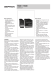
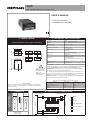
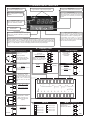
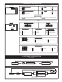
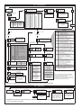
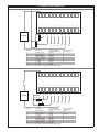
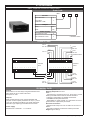
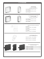
2308
MULTIZONE INDICATOR / ALARM UNIT
USER’S MANUAL
SOFTWARE VERSION 4.x
code 80330B / Edition 08 - 06/09
2 • TECHNICAL SPECIFICATIONS
1 • INSTALLATION
• Dimensions and cut-out; panel mounting
108
Resolution
4000 pt
Accuracy
0.2% f.s. ±1 digit for linear inputs
0.5% f.s. ±1 digit for TC, RTD, mVac inputs
Acquisition speed
Thermocouples
160msec per channel
J, K, S, R, T
Resistance Thermometer
RTD Pt100 2-wires
RTD Pt100 3-wires
Power supply
100...240Vac/dc ±10%
11...27Vac/dc ±10%
50/60Hz, 10VA
Relay output
NC/NO selectable with jumpers
(5A/220Vac cosϕ = 1) (1,5A cosϕ = 0,2)
115
96
48
Logic output
70
44,5
25V/15mA max
- “Watch-dog” protection circuit for instrument reset
in case of interference
- 3 SW protection levels
- jumper to enable access to calibration from panel
keys
0...50°C
8-bit microprocessor
Protections
92
Work temperature
Function
157
CE MARKING: The instrument conforms to the European Directives 2004/108/CE and
!
2006/95/CE with reference to the generic standards: EN 61000-6-2 (immunity in industrial
environment) EN 61000-6-3 (emission in residential environment) EN 61010-1 (safety).
For correct and safe
installation, follow
the instructions and
observe the
warnings contained
in this manual.
10
MAINTENANCE: Repairs must be done only by trained and specialized personnel.
Cut power to the device before accessing internal parts.
Do not clean the case with hydrocarbon-based solvents (Petrol, Trichlorethylene, etc.).
Use of these solvents can reduce the mechanical reliability of the device. Use a cloth
dampened in ethyl alcohol or water to clean the external plastic case.
SERVICE: GEFRAN has a service department. The warranty excludes defects caused
by any use not conforming to these instructions
EMC conformity has been tested with the following connections
FUNCTION
Power supply cable
Relay output cable
Digital communication wires
TC input
Pt100 input
Panel mounting:
To fix the unit, insert the brackets provided into the seats on either side of the
case. To mount two or more units side by side, respect the cut-out dimensions
shown in the drawing.
max.6,9
Low-signal line
Feeder and output line
A
6...7
With fork terminal;
with tinned wire;
with ring terminal
80330B_MHW_2308_0609_ENG
D
B
A
SERIAL
B
INPUTS
C
MD81 EXPANSION
D
OUTPUTS /RELAYS
E
FEED
E
+
Channel
STANDARD VERSION
WITH SCREW TERMINAL
max.6,9
LENGTH
1m
3,5 m
3,5 m
5m
3m
4 • SUGGESTED CONNECTIONS
22
21
20
19
18
17
16
15
14
13
12
1
2
3
4
5
6
7
8
9
10
11
Channel
3 • TERMINALS
CABLE TYPE
1 mm2
1 mm2
0,35 mm2
0,8 mm2 compensated
1 mm2
C
1
5 • DESCRIPTION OF FACEPLATE
Auxiliary display
Indication of displayed channel
Main display
Displays the variables for the 8 channels
Signal: alarms 1 and 2 relays energized
REM serial communication
signals, configuration for 8 inputs
100mVac
Function button
Used to select the various channels when the
instrument operates in manual and to end the
configuration and calibration procedures at
any time
“Calibration” button
Gives access to various steps of
instrument calibration procedure
Plate showing units of
measurement
“Configuration” button
Gives access to various steps of normal (alarm
setting) and complete calibration procedure for
the instrument
“Raise” and “Lower” buttons
Lets you raise (lower) any numerical value or
choice of optional. •• Raising (lowering) speed
is proportional to duration of pressing time. ••
The procedure is not cyclical; i.e., once the
maximum (minimum) value for the setting is
reached, the raise (lower) function is blocked
even if the button remains pushed.
“Man/Auto” channel scan button
Switches operation from manual to automatic and vice versa. In manual, channel scanning is done
with the “Function” button. In automatic (decimal point of auxiliary display ON), scanning is automatic.
•• Press the key at any point of the configuration procedures to display the software version. Small
display: “U”; Large display: n version. This display persists until the key is pressed again.
6 • CONNECTIONS
• Inputs (See HW configuration)
Available thermocouples:
J, K, S, R,T
• TC
In
+
1
- Observe polarities
- For extensions, use the
correct compensating cable
for the type of TC used
-
• RTD Pt100 2-wires Use wires of adequate diameter
(min. 1,5mm2)
In
1
• RTD Pt100 3-wires
In
In
• Serial line
18
21
Connection
RS485
15
Rx
+
14
20
Standard:
100...240Vac/dc ±10%
A (Data -)
19
18
NO/NC
13
~
12
~
+IN5
+IN6
+IN7
+IN8
D
CK
15
14
13
12
3
4
5
6
7
8
9
10
11
+
+IN4
16
-
+IN3
2
-
17
+
+IN2
1
Rx
P
O
W
E
R
S
U
P
P
L
Y
O
U
T
1
M
D
8
1
NO / NC
O
U
T
2
NO / NC
S
E
R
I
A
L
L
I
N
E
Potentiometer ≥ 1KOhm
18
-
+IN1
19
+
21
+
22
Tx
Scale in direct voltage
0…20, 0…50, 0…10 mV,
0…10V
Scale in direct current
0…20, 4…20 mA
20
C
All. 1
+
Optional:
11...27Vac/dc ±10%
Rx
Use wires of adequate
diameter (min. 1 mm2)
The 3-wire resistors take up 2
inputs: the actual input must
be odd (1-3-5-7), and the next
channel, even, for the third
wire.
NO/NC
• Power Supply
A (Data +)
Tx
NOTES:
For a 15m cable with 1.5 mm2
section, the error is
approximately 1°C.
C
All. 2
+
+
-
22
Max
In
With 10V power only
(reference to S6 Power
jumper)
INPUTS
1
Min
0...100mVac
• Vac
~
Common
2
19
16
-
• Potentiometer
20
Resistance in series to the
diode is 1KΩ; in series to the
transistor collector is 100Ω
17
COMMON
GND
1
Tx
+
V
In
21
Connection
Parallel Current Loop
1
• Linear
• Alarm outputs
Contact capacity
5A/220Vac
For logic output
24V/15Ma
In
1
ATTENTION:
all 8 inputs must
be in mVac
1
2
3
4
5
GND
Channel 1 input
Channel 2 input
Channel 3 input
Channel 4 input
6
7
8
9
• MD81 (see paragraph 10)
Channel 5 input
Channel 6 input
Channel 7 input
The MD81 unit must be
placed near the
instrument (max 20cm)
11
CK
10
D
Channel 7 input
1
GND
80330B_MHW_2308_0609_ENG
7 • HARDWARE CONFIGURATION
Power board
Sensor / transmitter power (fastons 1-22)
S0
S6
S1
22
S6
15V
S6
10V
S3
S2
Alarm 1 (fastons 14-15)
NO Contact
S2
Digital communication connection (Rx)
S1
Parallel connection
S1
Serial connection
S2
NC Contact
Alarm 2 (faston 16-17)
S3
12
NC Contact
S3
NO Contact
Terminal 22 polarization
S0
S0
Terminal 22 = positive sensor feed
A
Terminal 22 = negative sensor feed
B
JUMPER A
CPU board
SV / S
ST / N / SI
TC, RTD, Vdc, Pot.. mA Inputs
Vac Inputs
S15A
11
S19
Jumper A
S9
S15B
S19
Temperature (°F - °C)
1
Access to calibration
S9
Serial line preset for
Parallel / Serial connection (TX)
S18
°C
S17
Disabled
S16
Serial connection
S18
°F
S17
Enabled
S16
Parallel connection
SVx
Potenz.; 0...10Vdc
JUMPER SV/S
Input type: single channel
Sv
S
Sx
channel 1
TC; RTD; mV; mA; Vac
channel 8
JUMPER ST / N / SI
Input type: single channel
ST
N
SI
channel 1
STx
TC
Nx
Vac/Vdc;
RTD; Pot.
SIx
0...20mA
4...20mA
channel 8
8 • SOFTWARE CONFIGURATION
8a • Display
F
Display
channel 1
DISPLAY CHANNEL 2
.......
DISPLAY LAST CHANNEL
SELECTED
8b • Alarm setting
If alarm is
normal
Display
CFG
CFG
F
Setting alarm limit
Display
Select alarm no. in range
1…10 with keys " ∆
∇"
Channels selected
(x - y)
If alarm = AND/OR
function of alarms
from x to y (ex. 3-5)
80330B_MHW_2308_0609_ENG
3
8c • Configuration
Serial communication
transmission speed
Display
Press CFG for
10 sec.
CFG
Software
protection
Prot Configuration
0
1
2
3
if
Enabled
Enabled
Disabled
Disabled
Alarm
setting
Enabled
Disabled
Enabled
Disabled
b
0
1
2
3
4
5
6
7
8
9
10
11
12
13
14
15
Baud rate
1200 bit/sec
2400 bit/sec
4800 bit/sec
9600 bit/sec
1200 bit/sec
2400 bit/sec
4800 bit/sec
9600 bit/sec
1200 bit/sec
2400 bit/sec
4800 bit/sec
9600 bit/sec
1200 bit/sec
2400 bit/sec
4800 bit/sec
9600 bit/sec
Protocol
Cencal
Cencal
Cencal
Cencal
Modbus
Modbus
Modbus
Modbus
Modbus
Modbus
Modbus
Modbus
Modbus
Modbus
Modbus
Modbus
=0
Parity
none
none
none
none
even
even
even
even
odd
odd
odd
odd
if
with keys " ∆
∇"
Access to
configuration
phase
Set 0 to go to channel
configuration;
set 1…10 to go to alarm
configuration
C = 31 or 32
(AND/OR function)
J
K
R
S
T
Pt100/2
Pt100/2
Pt100/3
Pt100/3
0...800°C / 32...1472°F
0...1300°C / 32...2372°F
0...1600°C / 32...2912°F
0...1760°C / 32...2912°F
-100...400°C / -148...752°F
0...20mA
4...20mA
100m Vac (only HW config.)
0...20mV
0...50mV
0...100mV
0...10V
-200...400°C / -328...752°F
-99,9...100,0°C / -99,9...212,0°F
-200...400°C / -328...752°F
-99,9...100,0°C / -99,9...212,0°F
Potentiometer
No. first
alarm
Setting
decimal point
0
0
LINEARS
Press the “Raise” and
“Lower” keys to move the
decimal point
Fixed decimal
Setting alarm
hysteresis
value
t>F
Selection of event
type for alarm
filter 1,2Hz
0= filter ON
1= filter OFF
Setting value of
alarm limit
(*)
1
Digital filter
alarm 3...10
Fixed
1...8
channel
Hyst 1 ÷ 2 = -999...9999
Hyst 3 ÷ 10 = -128...127
TC/RTD
Setting minimum LINEARS
-999...9999 Scale range
scale value
TC/RTD
Setting maximum LINEARS
-999...9999 Scale range
scale value
C = 1...30
(normal alarm)
Absolute = scale range
Deviation = -999…9999
No. last
alarm
1
AND (C = 31)
Alarm active
if all alarms are
active (ON)
Alarm active if at
least 1 alarm is
deactivated (OFF)
OR (C = 32)
Alarm active
if at least 1
alarm is
active (ON)
Alarm active
if all alarms
are deactivated
(OFF)
CFG
All alarms
Alarm not engaged
Alarm assigned to channel 1…8;
alarm setpoint is absolute
Alarms 1 and 2 only
9
Alarm assigned to all channels; alarm
setpoint is absolute; alarm is active if all
channels are in alarm state
10
Alarm assigned to all channels; alarm
setpoint is absolute; alarm is active if at
least one channel is in alarm state
11...18 Deviation alarm assigned to channel 1…8;
alarm setpoint relates to setpoint of alarm
(3…10) assigned to channel
19
Alarm assigned to all channels; for each
channel, alarm setpoint relates to setpoint of
alarm (3…10) assigned to channel; alarm is
active if all channels are in alarm state
20
Alarm assigned to all channels; for each
channel, alarm setpoint relates to setpoint of
alarm (3…10) assigned to channel; alarm is
active if at least one channel is in alarm state
21...28 Alarm assigned to channel 1…8; alarm
setpoint defines a symmetrical event
window around the setpoint of alarm (3…10)
assigned to channel
29
Alarm assigned to all channels; for each
channel, alarm setpoint defines a
symmetrical event window around the
setpoint of alarm (3…10) assigned to
channel; alarm is active if all channels are in
alarm state
30
Alarm assigned to all channels; for each
channel, alarm setpoint defines a
symmetrical event window around the
setpoint of alarm (3…10) assigned to
channel; alarm is active if at least one
channel is in alarm state
31
AND function for multiple alarms (3…10)
32
OR function for multiple alarms (3…10)
0
1...8
Setting (alarm 1 and 2) and
display (alarm 3…10) of
channel assigned to alarm
Selection of input type
F
Set no. of channels
(1…8) actually used
(+8 to enable
automatic scanning)
Select a no. in range
0…9999
= 1...10
From 1 to last channel
selected
0= return to alarm
configuration phase
Selection of
channel
0
1
2
3
4
5
6
7
8
9
10
11
12
13
14
15
16
Interface
CL/485
CL/485
485
485
485
485
485
485
485
485
485
485
485
485
485
485
Alarm
configuration
Input
configuration
No. of channels
actually used
Instrument code
for digital
communication
Setting alarm
event type
0
1
0
1
0
1
Absolute alarms
Alarm active
above limit
Alarm active
below limit
Deviation alarms
Alarm active above
(limit + absolute)
Alarm active below
(limit + absolute)
Symmetrical alarms
Alarm active
outside interval
Alarm active
inside interval
Note:
if U=1, alarm tripping under channel
conditions OR and AND is reversed from
9 to 30.
(*) For symmetrical alarms with negative hysteresis,
hysteresis is placed inside the window, whereas with
positive hysteresis it is placed outside.
The minimum alarm (positive hysteresis, type 1 event)
is automatically excluded in the startup phase until the
input variable has exceeded the set limit.
Move from one configuration phase to another by pressing the CFG key; press the F key to go to display.
8d • Calibration
Display
CAL
If jumper S17 is
present
(see para. 7)
Selection of
channel to be
calibrated (1…8)
Display type of input to be
calibrated
No. of selected
channel
No. of selected
channel
(see para. 8c)
Display room
temperature setting *
for TC only
With a calibrator or
generator, transmit a signal
equal to min. scale value to
the corresponding input. For
input 4…20mA, give a
minimum value of 0mA.
Transmit a signal equal
to max. scale value to
the corresponding input
of the instrument.
ATTENTION: the instrument is supplied calibrated; any additional calibration must be made by a trained technician equipped with the necessary
devices. The procedure is irreversible.
4
80330B_MHW_2308_0609_ENG
9 • CONNECTION EXAMPLES
Connection examples 1
22
21
20
19
18
17
16
15
14
13
12
1
2
3
4
5
6
7
8
9
10
11
I N1
I N2
I N3
I N4
I N5
I N6
I N7
I N8
+Tc
+Tc
+Tc
J
K
S
+10V
+4 / 20
mA
+50
mV
+
Transmitter.
-
Input no.
Input type
HW configuration
jumpers closed (on)
1
Potentiometer
SV1-N1
2
Potentiometer
SV2-N2
3
Thermocouple J
S3-ST3
4
Thermocouple K
S4-ST4
5
Thermocouple S
S5-ST5
6
0...10V
SV6-N6
7
4...20mA
S7-SI7
8
0...50mV
S8-N8
Reference for inputs in mV and TC is terminal 1
(common to all inputs) S11 - S12 - S14 - S15B - S19 = ON
SW configuration
t = input type
16
16
0
1
3
11
6
9
Connection examples 2
22
21
20
19
18
17
16
15
14
13
12
1
2
3
4
5
6
7
8
9
10
11
I N1
I N2
I N3
I N4
I N5
I N6
I N7
I N8
+50
mV
+4 / 20
mA
+Tc
+Tc
+Tc
J
K
S
V ext
+
+
Transmitter.
RTD 3 F
-
Input no.
RTD 2 F
HW configuration
jumpers closed (on)
1
RTD 3-wires
S1-N1
2
(3rd wires RTD)
S2-N2
3
RTD 2-wires
S3-N3
4
0...50mV
S4-N4
5
4...20mA
S5-SI5
6
Thermocouple J
S6-NT6
7
Thermocouple K
S7-ST7
8
Thermocouple S
S8-ST8
Reference for inputs in mV and TC is terminal 1
(common to all inputs) S11 - S12 - S14 - S15B - S19 = ON
80330B_MHW_2308_0609_ENG
Input type
SW configuration
t = input type
14 (15)
-1
12 (13)
9
6
0
1
3
5
10 • ACCESSORIES
• MD8 - Expansion module for 8 alarm relays -
Order code
MD8
Version
For model 2300
0
For models
3500/4500 - 2308
1
Output
Relay
R0*
Static
D2
Power supply
11...27Vac/dc ±10%
0
100...240Vac/dc ±10%
1
* Standard version
CONNECTIONS
OUT 9
NO / NC
(-)
(+)
(+)
(-)
OUT 8
NO / NC
C (-)
OUT 10
(+)
(-)
NO (+)
NC
OUT 7
NO / NC
POWER SUPPLY
22
21
20
19
18
17
16
15
14
13
12
22
21
20
19
18
17
16
15
14
13
12
GEFRAN
2308
1
2
3
4
5
6
7
8
9
10
GEFRAN
MD8-1
11
1
2
3
4
5
6
7
8
9
10
11
(-)
D
(+)
CK
(-)
GND
OUT 3
NO / NC
(+)
(+)
(-)
(-)
(+)
OUT 6
NO / NC
OUT 5
NO / NC
OUT 4
NO / NC
TECHNICAL DATA
Signals
8 red LEDs turn on with relays energized and flash when
alarm limits are set on master instrument
Red power on LED
Outputs
Relay outputs with NA or NC contact selectable with
jumpers. Contact capacity 5A/220Vac to cosϕ=1 (1.5A to
cosϕ=0.2). Protection with MOV 275V spark suppressor
Alternate: logic outputs type D2 PNP 24V/15mA max
Power supply
Standard 100...240Vac/dc - 11...27Vac/dc
6
Absorbed power: 4VA.
Working temperature: 0÷50°C
Case
- Policarbonato autoestinguente V0; dimensioni frontali
96x48; profondità incasso 152mm; foratura 92x45mm.
- Fissaggio a retroquadro con staffette in dotazione.
- Estraibilità frontale parte elettronica.
- Disponibilità di calotte frontali con guarnizioni fino ad un
grado massimo di protezione pari a IP65.
Electrical connections
- Split terminals accept one 6.35 mm faston or two 2.8 mm
fastons
- Terminals completely recessed for accident prevention
Weight: approx. 600 gr
80330B_MHW_2308_0609_ENG
11 • ACCESSORIES
Polycarbonate cap
Protection level IP54
(frame) grey / (door) transparent
For instruments size 96x96mm (1/4 DIN)
Order code 51065
For instruments size 48x96mm (1/8 DIN)
Order code 51066
Polycarbonate cap with rubber gasket
Protection level IP65
(frame) grey / (door) transparent
For instruments size 96x96mm (1/4 DIN)
Order code 51064
For instruments size 48x96mm (1/8 DIN)
Order code 51067
Dust-proof polycarbonate cap (transparent)
Mod. CFA110
48x48mm (1/16 DIN) - order code 51060
Mod. CFA120
48x96mm (1/8 DIN) - order code 51061
Mod. CFA220
96x96mm (1/4 DIN) - order code 51062
Silicon rubber protection
Protection level IP65 (transparent)
48x48mm (1/16 DIN) - order code 51183
48x96mm (1/8 DIN) - order code 51185
96x96mm (1/4 DIN) - order code 51186
Instrument hole plug in self-extinguishing
polycarbonate V0 (grey)
Mod. Q48, for hole 45x45mm for instruments size 48x48mm
(1/16 DIN) - order code 51177
Mod. Q94, for hole 45x93mm for instruments size 48x96mm
(1/8 DIN) - order code 51178
Mod. Q96, for hole 93x93mm for instruments size 96x96mm
(1/4 DIN) - order code 51179
80330B_MHW_2308_0609_ENG
7
ORDER CODE
2308
DIGITAL
COMMUNICATION
STANDARD CONFIGURATION
Hardware and Software
Serial Current Loop
1*
Serial RS485
2
CH1...CH8
- Thermocouple inputs J 0...800°C
Alarms
- Setting 500
- Hysteresis -1
- Relay energized above
set limit
- NO relay contacts
ALARM OUTPUT
Relay
R0*
Static
D2
Power output for 10VDC
external sensor
Enable automatic
channel scan
POWER SUPPLY
100...240Vac/dc
1*
Configuration and setting
enabled
11...27Vac/dc
0
Calibration disabled
* Positions marked with asterisk indicate standard model
Parallel connection
for serial line
Please, contact GEFRAN sales people for the codes availability.
• WARNINGS
!
WARNING: this symbol indicates danger.
It is placed near the power supply circuit and near high-voltage relay contacts.
Read the following warnings before installing, connecting or using the device:
• follow instructions precisely when connecting the device.
• always use cables that are suitable for the voltage and current levels indicated in the technical specifications.
• the device has no ON/OFF switch: it switches on immediately when power is turned on. For safety reasons, devices permanently connected to the power
supply require a two-phase disconnecting switch with proper marking. Such switch must be located near the device and must be easily reachable by the
user. A single switch can control several units.
• if the device is connected to electrically NON-ISOLATED equipment (e.g. thermocouples), a grounding wire must be applied to assure that this
connection is not made directly through the machine structure.
• if the device is used in applications where there is risk of injury to persons and/or damage to machines or materials, it MUST be used with auxiliary alarm
units. You should be able to check the correct operation of such units during normal operation of the device.
• before using the device, the user must check that all device parameters are correctly set in order to avoid injury to persons and/or damage to property.
• the device must NOT be used in inflammable or explosive environments. It may be connected to units operating in such environments only by means of
suitable interfaces in conformity to local safety regulations.
• the device contains components that are sensitive to static electrical discharges. Therefore, take appropriate precautions when handling electronic circuit
boards in order to prevent permanent damage to these components.
Installation: installation category II, pollution level 2, double isolation
• power supply lines must be separated from device input and output lines; always check that the supply voltage matches the voltage indicated on the
device label.
• install the instrumentation separately from the relays and power switching devices
• do not install high-power remote switches, contactors, relays, thyristor power units (particularly if “phase angle” type), motors, etc... in the same cabinet.
• avoid dust, humidity, corrosive gases and heat sources.
• do not close the ventilation holes; working temperature must be in the range of 0...50°C.
If the device has faston terminals, they must be protected and isolated; if the device has screw terminals, wires should be attached at least in pairs.
• Power: supplied from a disconnecting switch with fuse for the device section; path of wires from switch to devices should be as straight as possible; the
same supply should not be used to power relays, contactors, solenoid valves, etc.; if the voltage waveform is strongly distorted by thyristor switching units
or by electric motors, it is recommended that an isolation transformer be used only for the devices, connecting the screen to ground; it is important for the
electrical system to have a good ground connection; voltage between neutral and ground must not exceed 1V and resistance must be less than 6Ohm; if
the supply voltage is highly variable, use a voltage stabilizer for the device; use line filters in the vicinity of high frequency generators or arc welders;
power supply lines must be separated from device input and output lines; always check that the supply voltage matches the voltage indicated on the
device label.
• Input and output connections: external connected circuits must have double insulation; to connect analog inputs (TC, RTD) you have to: physically
separate input wiring from power supply wiring, from output wiring, and from power connections; use twisted and screened cables, with screen connected
to ground at only one point; to connect adjustment and alarm outputs (contactors, solenoid valves, motors, fans, etc.), install RC groups (resistor and
capacitor in series) in parallel with inductive loads that work in AC (Note: all capacitors must conform to VDE standards (class x2) and support at least 220
VAC. Resistors must be at least 2W); fit a 1N4007 diode in parallel with the coil of inductive loads that operate in DC.
GEFRAN spa will not be held liable for any injury to persons and/or damage to property deriving from tampering, from any incorrect or
erroneous use, or from any use not conforming to the device specifications.
8
80330B_MHW_2308_0609_ENG


![2308 (PDF/131Ko) [F]](http://vs1.manualzilla.com/store/data/006354194_1-c5492b6e29b762ae89a93d5ab72c5466-150x150.png)