1
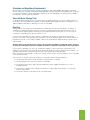
Installation& User Manual
Domestic Solar Hot Water Systems
1
Forced Circulation (Pumped) Open and Closed Loop Systems
Thermosiphon Open and Closed Loop Systems
Use of this Manual
This manual contains easy to follow procedures for the correct installation and operation of CHROMAGEN
Open and Closed Loop Thermosiphon and Pumped Solar systems.
Please take your time to read and understand the operating guidelines provided to ensure successful
and trouble-free operation of your Chromagen water heater. If you have any questions, contact your local
CHROMAGEN customer service representative on 1300 367 565.
2
Index
Installer to complete4
Glossary5
Chromagen the company6
Consumer information 6
Installation information 10
Maintenance and service calls 32
Electrical water heater information 33
Solar controller information 35
Warranty 36
3
Installer to Complete
Installation Address
Date of installation
Approximate angle of collectors ( ) degrees East / West Of North
Tank size ( )litres. Tank Type: Horizontal / Vertical And Open / Closed Loop
Water pressure (incoming) kPa Note: Pressure limiting valve required if over 650kPa
Electrical connection is Continuous/Off Peak, with Thermostat set at ( Gas Pressure (gas boost only) ( Flow valve set to ( )kPa Static ( )kPa loaded (all appliances running)
)l/min (0.75 l/min for single panel, 1.75 l/min for multiple panels)
Tempering valve operation tested and temperature adjusted to ( )degrees Celsius
Warranty Manuals and documents given to customer
Y/N
System operation explained to customer
Y/N
All pipe-work insulated in line with AS/NZS 3500 and local requirements
Y/N
Frost valve (if fitted) operation explained to customer
Y/N
Installer Company Name
Installer Name
License Number
Chromagen Pty Ltd
For service, call: 1300 367 565
4
)degrees Celsius
Contact Number
Glossary
Absorber Plate��������������������������������������� The part of the collector that collects the solar energy and transforms
it to heat.
Booster��������������������������������������������������� A supplementary heat source i.e. electricity, gas.
Close Coupled Solar����������������������������� Where the solar storage tank and solar collectors are connected
close together.
Closed Loop������������������������������������������� Using a heat exchange fluid to heat the potable water via a heat
exchanger.
Differential Controller��������������������������� An electrical device that reads the difference between the Collector
temperature and the stored water temperature to control the solar
input.
Element�������������������������������������������������� A thermostatically controlled booster element heats the stored water
in conjunction with the available solar energy.
Continuous Water Heater��������������������� A gas booster that only heats the water as it flows through it.
Glycol (Heat Exchange Fluid)��������������� Transfers the solar energy to the stored potable water via a heat
exchanger, prevents freezing or clogging of collectors in bad water
areas.
Non Return Valve����������������������������������� Also known as a check valve, allows liquid to flow in only one
direction.
Off Peak�������������������������������������������������� Electrical power supplied at a prearranged time.
Thermosiphon Arrest Valve������������������ Ensures the thermosiphon system will not overheat.
Pumped Solar System��������������������������� Utilises a pump to circulate the fluid from solar collectors to the
storage tank.
Pressure Limiting Valve������������������������ A valve connected to the cold water inlet to the water tank to control
the water pressure.
Pressure/Temperature Relief Valve����� A valve installed in the water tank to relieve excessive pressure and
temperature.
Potable Water���������������������������������������� Drinking water
Selective Surface����������������������������������� The special treatment given to the surface of the absorber plate.
Storage Tank������������������������������������������ A lined water tank for storing the heated water.
Solar Collector��������������������������������������� Glazed flat-plate collector where the fluid passes through copper
tubes and is heated by solar energy.
Tempering valve������������������������������������ A valve used to control the delivery temperature of the stored water.
Thermosiphon���������������������������������������� As fluid is heated it becomes less dense (lighter) and rises, as it
becomes colder it becomes denser (heavier) and falls causing
thermosiphoning.
Thermostat��������������������������������������������� Automatically switches the booster on and off to maintain the
temperature in the storage tank.
5
Chromagen the Company
Chromagen has been manufacturing and installing solar water heaters throughout the world since 1962.
Since then, we have developed a system of solar energy absorption, transfer and storage so advanced,
that we are at the forefront of the solar water heating industry today. CHROMAGEN provides two basic
configurations, in a range of sizes and models.
Thermosiphon Closed Coupled Systems
The traditional roof mounted thermosiphon solar
hot water systems are available in 200 and 300 litre
tank sizes with one, two, or three solar collectors.
The solar system utilizes natural thermosiphon to
maximize solar efficiency. In areas where there is
the possibility of freezing, frost protection must be
used. As the use of a ‘closed loop’ system may be
required, always discuss your options with your local
Chromagen expert.
Split Pumped Systems
When aesthetics are an important consideration,
Chromagen’s range of pumped solar water heaters
are installed with the storage tank mounted at
ground level, with one, two or three solar collectors
mounted onto the roof. Chromagen’s ‘smart’ solar
controller monitors water temperature and uses
available solar energy to ensure maximum solar
savings. In areas where water is prone to freezing,
closed loop systems or systems with evacuated
tube collectors must be installed for frost protection.
As the use of a ‘closed loop’ system may be
required, always discuss your options with your local
Chromagen expert.
Consumer Information
General information and operating guidelines for Chromagen Water Heaters
The general performance and energy savings that you can expect from your Chromagen water heater
will depend upon a number of factors, such as water usage patterns, daily temperatures, available solar
energy and the cost and type of purchased energy being utilized.
Your Chromagen water heater is designed to utilize a combination of solar energy and purchased energy,
operating simultaneously, to maintain a minimum operating temperature of 60°C. To ensure that you
always have an adequate supply of hot water, we recommend that the auxiliary booster is left
switched ON at all times. The automatic thermostat will switch the auxiliary booster on and off
automatically.
Reliance on ‘solar energy only’, or minimizing auxiliary booster usage manually to unrealistic times, can
and will result in inadequate water temperatures, particularly during times of cool and inclement weather.
Overnight temperature stabilization results in a reduction in water temperature, as the hot water at the top
of the storage cylinder transfers some of its heat to the cooler water in the lower part of the cylinder. This
effect is often perceived as ‘heat loss’ by consumers who control their boosting to minimal times. Utilizing
the auxiliary booster as recommended will ensure that the effects of overnight temperature stabilization
have no effect on the water temperature in the home.
6
To ensure adequate hot water is available at all times, it is important to follow our simple operating
guidelines.
Standards and Regulatory Requirements
All Chromagen solar hot water systems must be installed by an authorized plumber. All installation work must
meet local authority standards, Australian Standard (AS/NZS 3500.4) and the National Plumbing Code along with
local electrical regulations. Where required, the relevant electrical and plumbing work will need to be certified to
the satisfaction of local regulatory authorities.
Solar Hot Water Storage Tank
To obtain maximum performance the solar tank/system should be positioned as close as possible to the most
used outlets. The solar pumped storage tank can be installed internally (dependant upon local regulations) on an
approved spill tray with drain or externally, on a level concrete plinth.
Boosting
Average annual solar savings are calculated with the ‘auxiliary booster’ left in the ‘ON’ position at all times. It
is important to understand that the system is not always consuming purchased energy when the ‘booster’ is
on, as the system regulates purchased energy use via an inbuilt automatic thermostat. It is not necessary for
consumers to manually turn the ‘booster’ switch on / off.
If your system is operating on a solar / electricity combination, Chromagen recommend that the electrical
booster is connected to standard ‘Day Rate’ electricity to ensure an adequate supply of hot water at all times. To
maximize the amount of solar savings available, a time clock can be fitted to supply electricity to the booster at
selected times.
Systems that use electrical boosting can be connected where available to “Off Peak” power, however
to ensure that adequate hot water is available at all times a ‘Day Rate’ facility will need to be provided.
If your system is operating on a solar / gas combination, utilizing a continuous flow gas water heater as the
auxiliary booster, the gas water heater will need to be left with the power and gas switched ‘ON’ at all times. For
operating and maintenance information, please refer to the separate gas manual provided.
When using gas boosting through a continuous hot water system, the gas system should be as close as possible
to the most used outlets.
Solar systems can also be used for pre-heating to an existing hot water heater provided that –
|| The existing water heater is thermostatically controlled, not flow controlled.
||
The operating pressure of the two systems is compatible.
||
The existing water heater is able to provide adequate hot water supplies during times of cooler or inclement weather.
||
The warranty or lifespan of the existing water heater is not affected by the installation of a solar water
heater as a pre heater.
||
The electric element is removed from the solar water heater.
7
Hot Water can be DANGEROUS
WARNING
HOT WATER BURNS. As a safety precaution, young children should always be
supervised around hot water fixtures.
Hot water systems can store water at temperatures that can cause scalding. Water temperatures over
50°C can scald and care needs to be taken to ensure that injuries do not occur through incorrect use of
your water heater.
As solar water heaters can generate water temperatures in excess of 85°C, regulations require that a
solar rated tempering valve be fitted to the heater to prevent water temperatures going to the home
exceeding a preset safe maximum. The tempering valve must be connected to the hot water outlet line
from the solar system. The valve must be fitted by an authorized plumber at the time of installation or in
retrofitting to existing systems.
Care should be taken to avoid coming into contact with any pipe work or fixtures associated with the
water heater collector flow and return lines. Water from the solar collectors can be hot enough to
create pressurized steam which can cause severe scalding - Under NO circumstances should
any ‘home handy man’ type modifications be attempted.
||
Appliance not intended for use by persons (including children) with reduced physical sensory
or mental capabilities, or lack of experience and knowledge, that prevents them from using the
appliance safely without supervision or instruction.
||
Children playing with the appliance. Children should be supervised by a responsible adult for their
safety to ensure that they do not play with the appliance.
||
DANGER: Failure to operate the relief valve easing gear at least once every six months may result
in the water heater exploding. Continuous leakage of water from the valve may indicate a problem
with the water heater.
||
THE INSTALLATION MUST COMPLY WITH THE REQUIREMENTS OF AS/NZS 3500,
AS/NZS 3000, and all local codes and regulatory authority requirements. In New Zealand, the
installation must conform to the New Zealand Building Code G12.
||
The power supply must be protected by an individual circuit breaker at the main electrical
supply switchboard and rated to suit the booster size. The supply to the solar water heater can
be operated directly from the switchboard or via a remotely mounted switch or time clock as
requested by the customer. The heater must be provided with a suitable means for disconnecting
the power supply.
How hot will the stored water be?
As a general rule of thumb, a correctly selected solar water heater can attain an average of twice the
ambient day time temperature from solar energy alone. In simple terms, on a clear cloudless day of
25°C, solar energy will raise the stored water to roughly 50°C. The auxiliary booster will then boost the
water to 60°C
During the warmer months, where daytime temperatures can exceed 40°C, temperatures can exceed
85°C. As thermosiphon systems have no ability to control temperature gained from solar input, we
recommend the use of a ‘thermosiphon arrestor valve’ in areas subject to high solar energy
conditions in instances where more than one solar collector is installed, as the stored water
can be heated to very high temperatures. Temperatures exceeding 95°C can result in the
temperature relief valve activating, which can result in large volumes of wasted water.
Chromagen’s range of split pumped systems utilize a solar controller designed to automatically cease
circulating water through the solar collector array once the stored water has reached a maximum of 85°C.
It is important to ensure that the power supply to the pump control unit is NEVER switched off during
normal ‘day to day’ operation.
8
Frost Protection
Chromagen ‘Open Loop’ split pumped systems are not suitable for installation where the ambient temperature
falls below 4°C and/or above 800 meters altitude without additional frost protection – systems installed under
these conditions suffering frost damage, will not be covered under Chromagen’s warranty program. Chromagen
Evacuated Tubes or closed loop systems are recommended for these sites.
Chromagen recommend the use of ‘Closed Loop’ (Thermosiphon or Vertical) systems in areas of
known frost. Thermosiphon Open loop Systems exposed to infrequent frost conditions must be
installed with one Frost protection valve per panel
If a Chromagen ‘Open Loop’ split pumped system is to be installed in an area subject to freeze conditions, an
approved freeze protection valve MUST be fitted to protect against frost damage. Where more than 1 panel is
installed a freeze protection valve should be installed on each panel. Systems not fitted with an approved freeze
protection valve suffering frost damage will not be covered under Chromagen’s warranty program.
Chromagen’s range of ‘Open Loop’ split systems are fitted with an inbuilt frost protection mechanism in the
solar control unit designed to automatically circulate a small amount of water through the solar collector array
when freeze conditions occur. It is important to ensure that the power supply to the pump control unit is NEVER
switched off during normal day to day operation. If you are unsure about the level of frost protection required in
your area please contact your Chromagen solar specialist on 1300 367 565
Chromagen’s warranty will not apply to frost damage collectors if the pump and or controller are determined to
be faulty for any reason, including power failure except within the first 12 months.
It is the home owner’s responsibility to check the system before winter to determine that the system is circulating
water to the collectors. This can be done by checking temperature of the pressure relief valve on a sunny day in
the late afternoon. If the valve is hot the pump and controller are working properly and this verifies that the frost
protection will function correctly.
Failing to perform this check will render the home owner liable for the full expense of collector replacement should
frost damage result.
Going away on holidays?
If the water heater is left unused for two weeks or more, a small quantity of hydrogen gas (which is highly
flammable) may accumulate in the top of the water cylinder. To dissipate this gas safely it is recommended that
a sink or bath hot tap be turned on to dispel a couple of litres of water. During this procedure there should be no
smoking, open flames or any electrical appliances such as washing machines or dish washers operating nearby.
If hydrogen is discharged through the tap, it will make a sound like air escaping.
9
Installation Information
Water Quality
Town water supplies are generally a controlled water source and should not cause any difficulty with the
system. Some water may have elevated mineral content and require more frequent system maintenance.
Chromagen ‘Open Loop’ systems are suitable for use with water supplies with a total dissolved solid
content less than 1000 ppm and in which the total hardness does not exceed 200 ppm CaCO3. If the
local water supplies have calcium hardness (CaCO3) exceeding 200 ppm, and an alkalinity in excess of
150 ppm, then a Chromagen ‘Closed Loop’ system should be selected. Your local water supply authority
can supply a water analysis if required, or simply contact Chromagen’s Customer Services on
1300 367 565. Water Pressure
The storage tank has a pressure/temperature relief valve set at 1,000 kPa. The cold water inlet pressure
should not exceed 800 kPa (approximately 20% below the pressure relief valve setting). A pressure
reduction valve must be installed if this is not the case. The relief valve will discharge a small amount of
water when the system is heating and should be checked every six months
WARNING
Any checks of the PTR should be performed when the tank is cold to prevent
exposure to scalding hot water.
Please note: It is important to remember that when a pressure limiting valve (PLV) is also fitted, that
the cold water line to the tempering valve is run ‘after’ the PLV to ensure that there is equal pressure from
both the hot and cold water lines going to the tempering valve.
Selecting System Location
The collectors should be installed facing the equator. South in the Northern Hemisphere, North in the
Southern Hemisphere (systems should face North in Australia). A deviation of 45° to east or west has little
effect on annual solar gain. The solar collector should be no more than 15 metres away from the storage
tank (in pumped systems). The collector/s must be at a minimum pitch of 10°, with flat roof frames
available if less than 10° roof pitch. 30° pitch and over requires extra fixings and frames. The solar system
should be free from shade all year round and clear from obstructions.
Roof Support Requirements
No extra roof supports are needed when installing a Chromagen pumped system in most cases, as a
collector when full weighs between 32 kg and 51 kg and covers an area of between 1.7 and 2.8 square
meters depending on the model. The collectors sit flat on the pitch of the roof.
Chromagen’s thermosiphon systems can weigh in excess of 500kg and therefore the structural strength
of the roof should be ascertained and its ability to support the weight prior to installation.
When installed in cyclonic areas, the use of an approved Chromagen cyclone frame will be required. If
you have any queries regarding the requirements of your location please contact your local Chromagen
Customer Services representative on 1300 367 565. For installation instructions, please refer to the
instructional leaflet provided with the frame.
Electric Connections
Local codes must be adhered to for all electrical work and be undertaken by a qualified electrician. Both
thermosiphon and split pumped systems will need the element connected for auxiliary boosting (see data
plate for power rating on hot water tank). All pumped solar hot water systems require a general power
outlet to run the pump. When using a gas booster an additional general power outlet will be needed.
Safety
Solar hot water systems can be heavy so always use approved lifting devices when installing solar
systems at heights. All Occupational Health and Safety issues must be adhered to.
10
Installation of Pumped Solar Systems
Installing the Collectors
WARNING
Solar collectors can generate temperatures that can scald. Exercise extreme care
when handling systems, paying special attention to the inlet and outlet fittings.
Chromagen advise covering the solar collector during installation.
WARNING
If solar collectors are not connected to the solar storage tank for extended periods
(eg; on new home installations) it is important to ensure that collector flow and return
lines are emptied of water after pressure testing has been completed. Failure to
drain flow and return lines can lead to dangerous, scalding water temperatures being
released during tank ‘fit off’, or damage to collectors due to over pressurization.
After selecting the position of the tank and collectors (making sure they are generally no more than 15 metres
apart), check the roof for broken or loose tiles and rusted or loose steel sheets and make good.
Position the collector rail on the front edge of a tile or over a batten and with the straps supplied, fix them to/
through the roof. Tilt the collector rail slightly on the hot outlet side to allow any air to be bled from the highest
point.
Before lifting the collector/s onto the roof, we recommend you install all brass fittings to the collectors. Due
to the high temperatures generated, the use of standard Teflon is unsuitable. Only use a jointing system that
is rated for high temperatures i.e. Hemp and TOT thread sealant, used with Loctite 569 (Hydraulic Sealant),
Loctite 55 pipe sealing cord, or Loxeal. It’s the installers responsibility to ensure the appropriate sealant is used.
Solar Collector Connections TWO/THREE COLLECTORS
Fit a ¾ MI x ½ inch Conetite union on the cold water flow inlet fitting (bottom of collector).
Fit ¾ MI inch brass plug in opposite fitting on collector array (non frost areas)
Fit ¾ MI x ½ inch hex nipple and frost valve in opposite fitting on collector array (frost areas)
Fit a ¾ MI x ½ inch Conetite union on the hot water return outlet fitting (top of collector opposite side to cold)
Fit the ¾ MI x ½ FI inch reducing bush into the opposite fitting on the collector array
Fit the ½ inch brass sensor fitting into the brass bush.
Using the brass barrel unions connect the collectors together (if more than 1 collector).
In areas of frost, a frost protection valve will need to be connected to the collector array. Ask your
Chromagen solar specialist on 1300 367 565 when you need to include these valves.
The connection of the solar flow and return lines must be diagonal to each other with the flow in the bottom and
the return from the top on the opposite side.
Connecting the Collectors
Position the collector/s on the collector rail and tighten the collector barrel unions. Fix the collector/s onto the
collector rail using the screws supplied. Attach the top collector strap and fix to through roof.
Solar Flow and Return Lines
Run the solar flow and return lines from collector/s to tank using insulated copper with a gradual fall to the
storage tank. Approved flashing must be used when penetrating the roof.
WARNING
Under no circumstances should plastic piping be used.
11
Sensor Wire
The solar sensor wire will need to be run with the flow and return lines from collectors to tank. Make
sure the sensor wire is inserted into the sensor fitting and sealed. Make sure the sensor wire is protected
from damage. If this wire is cut or broken it will need to be rejoined, soldered and shrink sealed. Ensure
the sensor wire does not come into contact with the collector or tank flow and return line, as
very high temperatures can interfere with the sensor wire and cause the solar controller to
malfunction.
Care should be taken to ensure that the sensor wire is protected from damage by external
fixtures. The use of protective conduit is advised for all external areas.
Solar Tank Connections (see system diagrams page)
Position
The solar tank will need to be positioned on an approved base i.e. a concrete plinth and as close as
possible to the most used outlet or the gas booster if used. Base should provide ventilation, such as
ripple plinth on polyslab to prevent water retention
Solar Tank Connection Flow / Return.
Please refer to the system diagrams on page (16-27) for the correct installation.
Solar Differential Controller Installation
|| The controller must be fixed to the storage tank or the wall close to the tank using the fixing lugs
||
Fit the tank sensor fitting between the tank and controller
||
Connect the collector sensor wire to the fitting provided on the bottom of the controller
||
Plug the pump into the power outlet under the controller
||
Plug the controller into the GPO
||
Once tank is full of water, turn GPO on
Hot and Cold Water Connections
All plumbing connections must be done by a licensed plumber and in accordance with local authority
regulations.
Cold Water Connection
The cold water inlet connection to the solar storage tank is ¾ inch FI. The cold water inlet requires an
approved isolating non return valve. In some locations regulations require a pressure relief valve be fitted
to the cold water supply.
Hot water connection
The hot water outlet from the solar tank is ¾ inch FI. All hot water pipes must be insulated.
Installations on Flat Roof Stands
Flat roof stands are available for systems where the pitch of the roof is below 10°. Please refer to the
separate roof stand information sheet.
Filling and commissioning the solar system
12
1.
Turn on the cold water supply to the tank and open a hot water tap
2.
Turn on the solar controller
3.
DO NOT TURN ON THE GAS BOOSTER
4.
Wait till water starts to come out for the hot water tap
5.
Leave water running until air is bled, then turn off the hot water tap,
6.
Switch on the power and the gas supply to the gas booster
7.
Turn on the hot water tap inside the house to check if the booster is working and test the water
temperature.
CAUTION
Ensure the storage tank is completely full of water by bleeding the hot water lines via
an internal hot water tap (not the PTR Valve) before switching power on to the electrical
element or plugging in and operating the continuous flow gas water heater. Failure
to properly bleed the storage tank can in some cases cause damage not covered by
Chromagen’s warranty policy.
Open Loop Commissioning Procedure (See diagram page 16)
Turn on the mains cold water to the storage tank making sure there is a hot tap turned on in the home to bleed
all the air from the tank. When water begins to flow from the open tap, turn off.
When tank full, manually turn solar pump on to remove any air in solar collectors. Re-open internal hot water tap
to ensure all air is purged from the storage tank, then turn tap off. Once system is fully bled, plug in and turn on
the solar controller.
Closed Loop Commissioning Procedure (See diagram page 17 and 23)
1.
(Turn on the mains cold water to the system making sure the pressure / temperature valve is open. When
water flows from the pressure / temperature valve, close valve. Turn on a hot tap in the home to bleed all
remaining air from the tank and the hot water lines.
Check storage tank for leakage by pressure testing all fittings to a minimum of 800 kPa. Once any leaks
are rectified, the system is ready for use.
2.
Before introducing glycol to the system, ensure the solar collector is cold or well covered.
3.
Before introducing glycol to the system, loosen the Male Iron (MI) union that connects to ball valve #4, to
allow air to escape while filling the system. This will allow you to detect when the system is full.
4.
Introduce glycol into the closed loop system by filling a bucket with the glycol supplied in your kit. Connect
the bucket containing glycol to the ball valve (#5). Ensure that ball valve #4 is in the closed position. Then
using a hand pump charge the system with glycol. When the glycol is finished in the bucket, add water to
the bucket and continue to charge the system as necessary.
5.
When all air is expelled from the system, and the water that is discharged from the Male Iron union is clear
of bubbles, the system is fully charged. Tighten the Male Iron union to seal.
6.
Open ball valve #4
7.
Close ball valve #5
8.
Disconnect the hand pump
9.
To prevent damage or injury ensure the handles of both ball valves #4 & 5 are removed and the brass
plug (#6) is fully sealed.
10.Plug
the circulation pump in to the power socket underneath the controller (#2). Plug the controller and
continuous flow gas water heater into the GPO.
11.If
necessary uncover the solar collector.
WARNING
The closed circuit fluid operates at both high temperature and pressure. Inadvertent
opening of the circuit by householders could lead to severe injury. Once the closed
circuit is fully charged with the glycol solution and the circuit has been sealed by
closing the ball valve located at the storage tank, remove handle from ball valve and
seal off with brass fitting supplied.
13
Installation of Thermosiphon Systems
(Open and Closed)
After selecting the position of the system, check the roof for broken or loose tiles and rusted or loose
steel sheets and make good. The roof needs to be able to hold the weight of the solar system (up to
500kg). Measure down the required distance (which varies with different collectors) from where the front
leg of the tank will be positioned. It needs to be located on the front edge of a tile for support via the tile
batten below, or over the roof batten on a steel roof. Using the collector rail straps fix them to the roof
rafter by running them between the tiles or screwed through the roof into a batten on a steel roof. Tilt the
collector rail up slightly (10mm) on the collector hot return side to ensure thermosiphon occurs.
Before lifting the collector/s onto the roof, fit the connecting barrel unions to the collectors. Due to the
high temperatures the use of standard Teflon is unsuitable. Only use a jointing system that is rated for
high temperatures .i.e. Hemp and TOT thread sealant, used with Loctite 569 (Hydraulic Sealant), Loctite
55 pipe sealing cord, or Loxeal. It’s the installers responsibility to ensure the appropriate sealant is used.
Lift the collector/s into position and connect together. Fix the collectors to the collector rail using the
screws supplied. Lift the storage tank into position and centralize it on the top of the collectors, fixing the
rear tank straps to the roof rafters/battens. Using the connecting fittings and pipes, connect the tank and
collector/s together. (See system diagram page 26-27). For closed loop systems the installation of an
expansion tank and bleed/fill valve is needed.
In areas of frost, freeze protection valves can be connected to the collector array on the side opposite to
the cold water flow line, via a ¾ x ½ inch brass hex nipple in place of the bottom collector plug. Ask your
Chromagen solar specialist when you need to include these valves. Multiple panels may require additional
valves
Filling and commissioning
Open Loop
WARNING
Do not turn power on to the electrical element until the following procedure is
undertaken.
Turn on the mains cold water to the system making sure the pressure / temperature relief valve is open.
When water flows from the pressure / temperature relief valve, close valve. Turn on a hot tap in the home
to bleed all remaining air from the tank and the hot water lines.
Check system for leakage by pressure testing all fittings to a minimum of 800 kPa. Once any/all leaks are
rectified, the system is ready for use.
Closed Loop Tank
Turn on the mains cold water to the system making sure the pressure / temperature valve is open. When
water flows from the pressure / temperature relief valve, close valve. Turn on a hot tap in the home to
bleed all remaining air from the tank and the hot water lines.
Check storage tank for leakage by pressure testing all fittings to a minimum of 800 kPa. Once any/all
leaks are rectified, the system is ready for use.
Jacket and Collectors
14
||
Connect a half inch hose to the fill valve located at the bottom right hand corner of the solar
collector
||
Ensure that the test fitting located on the top of the tank is ‘unplugged’
||
Fill the collectors and tank jacket with potable water via the fill valve located at the bottom of the
collector/s until water flows from the test fitting located on the top of the tank making sure to bleed
all air from the jacket
||
Close fill valve and fit test fitting brass plug
||
Check all connections for leaks by pressurizing the system to 500 kPa
||
After testing the system, release the pressure from the jacket and introduce the antifreeze via the
fill valve located at the bottom of the collectors
||
Once full, close the fill valve and plug both the test fitting and the fill valve. The system should be
now free from air and ready for use
Propylene Glycol
Glycol should be added at a ratio of 35-60% of the volume depending on the local climate.
Chromagen’s Glycol solution is blue in colour. Although unlikely, if the water from your closed loop water heater
appears blue, then this may indicate a leak of the fluid from the heat exchanger into the stored hot water.
Chromagen Glycol is a food-grade fluid, and does not present a health hazard. However, the blue colour in the
water indicates that a service call is required, and your local Chromagen service office should be contacted. Call
1300 367 565.
WARNING
Although non toxic, Propylene Glycol MUST NOT be allowed to enter rain water
storage tanks.
Installation of collector / tank rails
For collector mounting frame to colorbond roofing;
1. Remove screws along batten line where panel rail is to be fastened
2. Mark hole locations and pre-drill collector mounting rail
3. Place rubber washers between collector mounting rail and roof surface at each hole
4. Reattach roofing screws through collector rail into existing screw holes of roof sheeting
5. Fasten collector to mounting rail
For collector mounting frame to tiled roofing;
1. Locate trusses and remove tiles above mounting points
2. Fold stainless steel strap in half and pass through vent slots on base in line with trusses
3. Secure a minimum of 3 screws through both sides of strap and into top chord of truss
4. Replace tiles
5. Fasten collector to mounting rail
For thermosiphon frame on colorbond roofing;
1. Remove screws along batten line where tank strap is to be fastened
2. Fold stainless steel strap in half and pass through tank mounting brackets in line with existing screw holes
3. Place rubber washers between tank mounting strap and roof surface at each hole
4. Reattach roofing screws through mounting strap into existing screw holes of roof sheeting
For thermosiphon frame on tiled roofing;
1. Locate trusses and remove tiles above mounting points
2. Fold stainless steel strap in half and pass through tank mounting brackets in line with trusses
3. Secure a minimum of 3 screws through both sides of strap and into top chord of truss
4. Replace tiles
15
Installation Diagram of Pumped Open Loop System
2
1
4
6
Continuous Flow Gas
water heater for
Gas boosted systems only
7
2
5
1
5
Part
3
11
1
2
3
4
5
6
12
8
7
950
8
620
10
9
460
7
170
8
TO BE SUPPLIED BY INSTALLER
8
9
10
11
12
Collector
Connecting KIT
Collector union
Connection union
Cold flow line
Sensor fitting (Collector)
Brass plug/frost valve
Hot return line
Sensor wire
(18m extension lead)
NON return valve
Pressure limiting valve
Duo valve
Tempering valve
PTR valve
6
1
5
4
Part Tank Connecting KIT
7
3
16
2
Part#
1
Solar controller
P0010
2
Solar pump
P0202
3
Sensor fitting
P0463
4
Flow control valve
P0483
5
Solar flow to collectors
6
Solar return from collectors
7
Cold supply to tank (800kPa max)
Part#
P0044
P0040
P0070
K0025
P0200
P0086
P0201
P0087
P0077
P0015
Installation Diagram of Pumped Closed Loop System
1
5
2
7
6
3
2
1
HOT OUTLET
Part
10
1
2
3
4
5
6
7
8
9
10
11
PTR VALVE
8
4
9
Collector Connecting KIT
Part#
Collector union
Connection union
Cold flow line
Brass plug
Sensor fitting (Collector)
Hot return line
Sensor wire (18m extension lead)
Pressure limiting valve
Duo valve
Tempering valve
NON return valve
P0044
P0040
P0029
P0463
P0151
P0201
P0087
P0077
P0086
11
TO BE SUPPLIED BY INSTALLER
1
5
4
10
6
3
2
Part
1
3
1
7
3
1
8
9
1
2
3
4
5
6
7
8
9
10
Tank Connecting KIT
Part#
Hex nipple
Solar controller
Brass tee
Bleed valve
Fill valve
Brass plug
MI x C union
Solar pump
Sensor fitting
Expansion tank
P0028
P0010
P0027
P0078
P0078
P0029
P0025
P0202
P0463
P0019
WARNING
The closed circuit fluid operates at both high temperature and pressure. Inadvertent
opening of the circuit by householders could lead to severe injury. Once the closed
circuit is fully charged with the Glycol solution and the circuit has been sealed by
closing the ball valve located at the storage tank, remove handle from ball valve and
seal off with brass fitting supplied.
DO NOT FILL GLYCOL WHILE THE PANELS ARE HOT - COVER THE PANELS WELL
BEFORE FILLING GLYCOL.
After commissioning fit pump cover
17
Smart Line 200 Litre Gas - Solar Open Loop System
I
A
G
Specifications
F
E
D
C
B
A
1260mm
Hot water outlet
B
100mm
Cold water inlet
C
460mm
Collector cold flow line
D
620mm
Collector hot return line
E
950mm
Pressure/Temperature Valve
F
1255mm
20mm Gas line
G
1870mm
Height
H
600mm
Width
I
1810mm
Flue Terminal
95
Kilograms (empty)
Weight
H
Filling and commissioning the solar system
1.
DO NOT TURN ON THE GAS BOOSTER UNTIL SYSTEM IS FULL
2.
Connect the various water pipes as per the adjoining diagram
3.
Open a hot water tap in the house and turn on the cold water supply to the tank
4.
Wait until water starts to come out of the hot water tap
5.
Leave cold water running until air is bled, then turn off the hot water tap in the house
6.
After no further air can be detected, plug the pump power lead into the solar controller
7.
Connect the solar controller to GPO
DOUBLE Check that all air has been purged from the system
8.
Loosen the nut immediately before the non return valve on the collector return line
9.
Allow water to flow until no further air is detected.
10.Re-tighten
11.Switch
the nut and check for leaks
on the power and the gas supply to the gas booster
12.Turn
on the hot water tap inside the house to check if the booster is working and test the water
temperature.
13.After
18
commissioning fit pump cover
Smart Line 200 Litre Gas - Solar Open Loop System
1
2
3
11
12
Part
Collector Connecting KIT
Part#
1
Sensor fitting (Collector)
P0463
2
Sensor wire (18m extension lead)
P0151
3
Cold flow line
4
Duo valve (to be supplied by installer)
P0087
5
Pressure limiting valve
(to be supplied by installer)
P0201
6
Hot outlet
7
Hot return line
8
Tempering valve
(to be supplied by installer)
P0077
9
Non return valve
P0086
10
PTR valve
P0015
11
Gas supply
12
Brass plug / frost valve
8
6
10
7
9
4
9
9
5
K0025
6
4
86
1 1
4
5
5
3
Part Tank Connecting KIT
4
Part#
1
Solar controller
P0010
2
Solar pump
P0202
3
Sensor fitting
P0463
4
Flow control valve
P0483
5
Solar flow to collectors
6
Solar return from collectors
7
Cold supply to tank (800kPa max)
3
7
7
2
2
19
Solar Easy 200 Litre Gas - Solar Open Loop System
I
A
G
Specifications
F
E
D
C
B
A
1260mm
Hot water outlet
B
100mm
Cold water inlet
C
460mm
Collector cold flow line
D
620mm
Collector hot return line
E
950mm
Pressure/temperature valve
F
1255mm
20mm gas line
G
1870mm
Height
H
600mm
Width
I
1810mm
Flue terminal
95
Kilograms (empty)
Weight
H
Filling and commissioning the solar system
1.
Position the tank with connections on the left hand
2.
Pop rivet (x 4) the top box to the tank
3.
Fix the top box to the wall
4.
Assemble the pump and other fittings as indicated in adjoining photo
5.
Connect the tank to booster hose (650mm)
6.
Connect solar flow to collectors
7.
Connect solar return at tank
8.
Connect cold water inlet and hot outlet
9.
Connect gas
10.Fill
tank and test
11.Connect
tank sensor white wire into sensor plug with silicon
12.Connect
collector lead into black adaptor from box
DOUBLE Check that all air has been purged from the system
13.Turn
on hot water tap in the house to ensure all air has been purged from the system
14.Switch
on the power and the gas supply to the gas booster
15.Commission
16.The
system is ready for use
17.After
20
the solar and gas booster
commissioning fit pump cover
Solar Easy 200 Litre Gas - Solar Open Loop System
1
2
3
11
12
8
Part Collector Connecting KIT
1
Part#
Sensor fitting
P0463
P0151
2
Sensor wire
3
Cold flow line
4
Duo valve (to be supplied by installer)
P0087
5
Pressure limiting valve
(To be supplied by installer)
P0201
6
Hot outlet
7
Hot return line
8
Tempering valve
(to be supplied by installer)
P0077
9
Non return valve
P0086
10
PTR valve
P0015
11
Gas supply
12
Brass plug / frost valve
6
10
7
9
4
9
9
5
K0025
6
1
5
4
Part Tank Connecting KIT
Part#
1
Solar controller
P0010
2
Solar pump
P0202
3
Sensor fitting
P0463
4
Flow control valve
P0483
5
Solar flow to collectors
6
Solar return from collectors
7
Cold supply to tank (800kPa max)
7
3
2
21
Smart Line 200 Litre Gas - Solar Closed Loop System
I
A
G
F
E
D
C
Specifications
A
1260mm
Hot water outlet
B
180mm
Collector cold flow line
C
290mm
Cold water inlet
D
715mm
Collector hot return line
E
945mm
Pressure/Temperature Valve
F
1255mm
20mm Gas line
G
1870mm
Height
H
600mm
Width
I
1810mm
Flue Terminal
95
Kilograms (empty)
Weight
B
H
Filling and commissioning the solar system
1.
(Turn on the mains cold water to the system making sure the pressure / temperature valve is open.
When water flows from the pressure / temperature valve, close valve. Turn on a hot tap in the
home to bleed all remaining air from the tank and the hot water lines.
Check storage tank for leakage by pressure testing all fittings to a minimum of 800 kPa. Once any
leaks are rectified, the system is ready for use.
2.
Before introducing glycol to the system, ensure the solar collector is cold or well covered.
3.
Before introducing glycol to the system, loosen the Male Iron (MI) union that connects to ball valve
#4, to allow air to escape while filling the system. This will allow you to detect when the system is
full.
4.
Introduce glycol into the closed loop system by filling a bucket with the glycol supplied in your kit.
Connect the bucket containing glycol to the ball valve (#5). Ensure that ball valve #4 is in the closed
position. Then using a hand pump charge the system with glycol. When the glycol is finished in the
bucket, add water to the bucket and continue to charge the system as necessary.
5.
When all air is expelled from the system, and the water that is discharged from the Male Iron union
is clear of bubbles, the system is fully charged. Tighten the Male Iron union to seal.
6.
Open ball valve #4
7.
Close ball valve #5
8.
Disconnect the hand pump
9.
To prevent damage or injury ensure the handles of both ball valves #4 & 5 are removed and the
brass plug (#6) is fully sealed.
10.Plug
the circulation pump in to the power socket underneath the controller (#2). Plug the controller
and continuous flow gas water heater into the GPO.
11.If
necessary uncover the solar collector.
12.After
commissioning fit pump cover
DOUBLE Check that all air has been purged from the system
Glycol should be added at a ratio of 35-60% of the volume depending on the
local climate.
22
1
2
3
11
12
8
6
Collector
Connecting Kit
Part#
1
Sensor fitting
P0463
2
Sensor wire
P0070
3
Cold flow line
Part
4
Duo valve
P0087
5
Pressure limiting valve
(to be supplied by installer)
P0201
6
Hot outlet
7
Hot return line
10
7
13
8
Tempering valve
P0077
9
Non return valve
P0086
10
PTR valve
P0015
11
Gas supply
12
Brass plug
P0046
13
Expansion tank
P0019
14
Solar pump
P0202
2
14
4
9
5
1
Tank
Part
Connecting KIT
Part#
1
Hex nipple
P0028
2
Solar controller
P0010
3
Brass tee
P0027
4
Bleed valve
P0078
5
Fill valve
P0078
6
Brass plug
P0029
7
MI x C union
P0025
8
Solar pump
P0202
9
Sensor fitting
P0463
10
Expansion tank
P0019
5
4
10
6
3
2
1
3
1
7
3
1
9
8
WARNING
The closed circuit fluid operates at both high temperature and pressure. Inadvertent
opening of the circuit by householders could lead to severe injury. Once the closed
circuit is fully charged with the Glycol solution and the circuit has been sealed by
closing the ball valve located at the storage tank, remove handle from ball valve and
seal off with brass fitting supplied.
DO NOT FILL GLYCOL WHILE THE PANELS ARE HOT - COVER THE PANELS WELL
BEFORE FILLING GLYCOL
23
Chromagen 400 Litre SplitLine Gas / Electric - Solar Open Loop System
A
Specifications
A
650mm
Tank width
B
1765mm
Tank height
C
271mm
Cold water inlet
D
1466mm
Hot water outlet
E
630mm
Collector hot return
F
271mm
Collector cold flow
G
450mm
Sensor Point
H
1466mm
PTR valve
Weight 126kg
Weight (empty)
B
H
D
E
G
C
F
Filling and commissioning the solar system
1.
DO NOT TURN ON THE GAS BOOSTER UNTIL SYSTEM IS FULL
2.
Connect the various water pipes as per the adjoining diagram
3.
Open a hot water tap in the house and turn on the cold water supply to the tank
4.
Wait until water starts to come out of the hot water tap
5.
Leave cold water running until air is bled, then turn off the hot water tap in the house
6.
After no further air can be detected, plug the pump power lead into the solar controller
7.
Connect the solar controller to GPO
DOUBLE Check that all air has been purged from the system
8.
Loosen the nut immediately before the non return valve on the collector return line
9.
Allow water to flow until no further air is detected.
10.Re-tighten
11.Switch
the nut and check for leaks
on the power and the gas supply to the gas booster
12.Turn
on the hot water tap inside the house to check if the booster is working and test the water
temperature.
13.After
24
commissioning fit pump cover
Thermostat
An adjustable thermostat is fitted and preset to 60°C. This can be adjusted to suit individual
requirements
Thermostat wiring
||
Wiring penetration should be made through the supplied grommet at the base of the
thermostat cover
||
Wiring must be performed by a competent licensed electrician in accordance with all
relevant standards
||
Wiring between element and thermostat is run through internal conduit between the 2
areas
||
Temperature calibration should be tested at time of commissioning.
WARNING
All Electrical Connections must be made by a licensed Electrician
1
4
Thermostat
(Electric boosted
systems only)
2
7
6
2
5
1
5
3
Continuous Flow Gas
water heater
(Gas boosted systems only)
8
10
15
10
14
9
TO BE SUPPLIED BY INSTALLER
13
10
12
11
Part System Parts Description
Part#
1
Collector union
P0044
2
Connection union
P0040
3
Cold flow line
4
Collector sensor fitting
P0070
5
Brass plug / frost valve
K0025
6
Collector return line
7
Collector sensor cable
(18m extensionlead)
P0200
8
Solar controller
P0010
9
Solar pump
P0202
10
Non return valve
P0086
11
Cold supply to tank (500 kPa max)
12
Duo valve (supplied by installer)
P0087
13
Pressure reducing valve (500 kPa)
P0201
14
Tempering valve (supplied by installer)
P0077
15
Flow control valve
P0483
25
Chromagen RoofLine (Thermosiphon) Open Loop System
Read individual instructions included with each system.
3
2
4
5
1
61
STORAGE TANK
TEMPERED WATER SUPPLY
7
COLD WATER SUPPLY
8
9
1
12
10
11
SOLAR COLLECTOR
Part Connecting KIT
1
Duo valve if required supplied by installer
2
Pressure limiting valve if required
(supplied by installer)
3
Tempering valve (supplied by installer)
4
Non return valve
5
PTR valve
6
20mm collector union
7
Hot return line (Collector to Tank)
8
Thermosiphon arrestor valve
9
20mm brass plug
10
Cold Flow Line (Tank to Collector)
11
Anti frost valve connection kit (if Required)
12
20mm brass plug or Anti frost valve connection kit
(if required)
THERMOSIPHON ARRESTOR VALVE
OPERATION
The thermosiphon arrestor valve (TA20) is fitted
to a thermosiphon solar hot water system
to limit the water temperature in the storage
cylinder to approximately 80°C. The valve
is located at the cold return to the collectors
and closes automatically when the water from
the bottom of the storage cylinder, passing
through the valve, reaches 60°C - 65°C. This
prevents any further thermosiphon action from
taking place until the temperature in the storage
cylinder reduces. When the water temperature
in the storage cylinder reduces (cools) the valve
opens automatically, allowing the syphon action
to resume.
To collector
Max Temperature:
Max Pressure:
Activation Temperature:
26
Cylinder
99°C
1400kPa.
60°C - 65°C
Chromagen RoofLine (Thermosiphon) Jacketed tank System
Read individual instructions included with each system.
3
2
4
1
STORAGE TANK
5
TEMPERED WATER SUPPLY
61
COLD WATER SUPPLY
7
8
12
9
10
11
9
10
SOLAR COLLECTOR
Part Connecting KIT
1
Duo valve if required supplied by installer
2
Pressure limiting valve if required (supplied by installer)
3
Tempering valve (supplied by installer)
4
PTR valve
5
Jacket Fill Point / Expansion Relief
6
20mm collector union
7
Non return valve
8
Cold expansion valve
9
Electrical Connections
10
20mm brass plug
11
Heat exchange fluid Flow Line (Tank to Collector)
12
Heat exchange fluid Flow Line (Collector to Tank)
27
WARNING
Evacuated tube collectors should not be unpacked from their protective packaging
until ready to install. The heat collected even in a short time of exposure to sun can
cause severe burns.
Tubes should not be stored where they could fall or where objects could fall on
them. Broken glass should be cleared immediately and disposed of appropriately.
Roof Support Requirements
No additional roof supports are required when installing a Chromagen pumped evacuated tube system in
most cases, as each 10 tube collector frame when full weighs approximately 40kg and covers an area of
approximately 1.7 square meters.
Connecting Collectors in Series
A maximum flow-rate of 15 L/min through tube type collectors is recommended.
The reasons for this are;
|| Excessive high flow rates can “scrub” the walls of the copper header, wearing it away.
||
High flow rates greatly increase the pressure drop, requiring a much larger circulation pump, wasting
electricity.
||
Peak 30 tube collector output is about 1.8 kW, therefore, the
maximum temperature rise per pass through the collectors will
be approximately 8°C at the maximum continuous flow rate
specified above. A faster flow rate provides no major benefit
and may result in the pump dropping below the pump delta-t
off (dTMin) setting and causing the pump to cycle ON/OFF.
||
Thermal expansion of more collectors in series could cause
buckling of the copper header during periods of stagnation.
Chromagen systems have a maximum number of 40 tubes
in series and a maximum flow rate of 0.1Ltr/tube/min. The
maximum flow-rate outlined above should not be exceeded by
the pump, even at 100% flow during variable speed control. For
a single collector, reaching flow rates 20-30% in excess of the
specified 0.1L/tube/min level is acceptable but, as described
above, will reduce the temperature rise and potentially cause
pump cycling.
Installing the Collectors
WARNING
Care must be taken while handling the evacuated tubes, as they may break
if knocked heavily or dropped. Safety glasses MUST be worn at all times when
handling evacuated tubes. If the evacuated tubes are struck by a hard object
with sufficient force (ie. branch falling on roof), they may break. During installation
consideration should be taken as to the possible path any broken glass may take.
Protection should be implemented to prevent broken glass from causing injury or
creating walking hazards to those below. The home owner should be made aware
by the installer of the location of the solar collector and the possible vicinity of broken
glass in the event of an extreme storm or object falling on the collector. Tubes should
be left in packaging and not exposed to light until ready for assembly. When installed
in the evacuated tube and in good sunlight, the heat pipe tip can reach temperatures
in excess of 200°C. At this temperature, touching the heat pipe will result in serious
burns. Appropriate personal protective equipment (PPE) must be worn when
handling hot tubes and heat pipes.
In an operational system, if the pump stops during daylight hours the collector header and surrounding
fittings, close to the manifold, can reach stagnation temperatures in excess of 160°C. ALWAYS use caution
when working around the collector and piping
28
4
Part
1
2
3
4
5
6
7
8
9
Continuous Flow Gas
water heater for
Gas boosted systems only
6
5
3
2
Collector Connecting
Part#
KIT
PTR valve
Cold flow line
Tempering valve
Sensor fitting
Hot return line
Sensor wire
Non return valve
Pressure limiting valve
Duo valve
P0015
P0077
P0070
P0200
P0086
P0201
P0087
1
7
950
7
620
9
8
460
6
170
7
TO BE SUPPLIED BY INSTALLER
WARNING
If solar collectors are not connected to the solar storage tank for extended periods
(eg; on new home installations) it is important to ensure that collector flow and
return lines are emptied of water after pressure testing has been completed. Failure
to drain flow and return lines can lead to dangerous, scalding water temperatures
being released during tank ‘fit off’, or damage to collectors due to over pressurization
and exposure to frost damage.
After selecting the position of the tank and collectors (making sure they are generally no more than 15 metres
apart), check the roof for broken or loose tiles and rusted or loose steel sheets and make good. If storage tank
is installed in interior locations it must be installed using an approved safe tray and drainage as per regulatory
requirements.
Position the collector rail on the front edge of a tile or over a batten and with the straps supplied, fix them to/
through the roof. A minimum of 2 straps must be used on the bottom rail and 2 on the top rail, per frame. Tilt the
collector rail slightly on the hot outlet side to allow any air to be bled from the highest point. This angle should not
be noticeable from the ground and should be 2-3 degrees in standard installations.
Before lifting the collector/s onto the roof, we recommend you install all brass fittings to the header manifold to
minimize the amount of time required on the elevated roof area. Due to the high temperatures generated, the use
of standard Teflon is unsuitable. Use only a jointing system that is rated for high temperatures i.e. Hemp and TOT
thread sealant, High Density Teflon used with Loctite 569 (Hydraulic Sealant), or Loctite 55 pipe sealing cord.
Attach the header to the black anodised frame by inserting the
studs on the underside to the rails, using the nuts and washer
provided. Take care to ensure the tube entry holes are on the
side of the manifold facing the longer side of the side sections.
The footer can then be attached to the two lower holes on either
side of the side sections using the bolts, washers and nuts
supplied. The footer should be installed with the threaded eyelets
facing away from the header.
Connections to Header Manifold
Fit a ¾ FI x ½ inch Conetite union on the cold water flow inlet fitting of manifold.
Fit a ¾ inch brass tee to hot water return outlet fitting of the manifold.
Fit collector sensor to end of brass tee.
Fit a ¾ MI x ½ inch Conetite union on the hot water return outlet fitting of brass tee.
29
Connections for Multiple Manifolds
As for installation of single manifolds for extreme left and right manifolds plus;
Fit ¾ inch brass collector union between manifold to connect them in series.
Repeat manifold connections up to a maximum of 40 tubes as above
*In areas of frost, a freeze protection valve will need to be connected to the collector array. Ask your
Chromagen solar specialist on 1300 367 565 when you need to include these valves.
Connecting the Headers
Position the header/s on the collector rail and tighten the collector barrel unions. Fix the header/s onto the
collector rail using the nuts and washers supplied. Attach the top header strap to the frame and securely
fix to/through roof. Ensure all possible water entry points are appropriately sealed.
Inserting the Evacuated Tubes
Remove the tubes carefully from the protective carton, taking care to avoid damage. Fit the rubber seal
and apply a small amount of heat transfer compound (white paste) to the top of the heat pipe. This
compound should not be handled without protective gloves, refer to paste manufacturer indicated on
packaging for MSDS.
Insert tubes through bottom footer eyelets and push into header pipe assembly.
Screw base cap into footer pipe to secure tube and gently tighten. Do not over-tighten as this may
damage glass tubes.
Solar Flow and Return Lines
Run the solar flow and return lines from collector/s to the tank using insulated copper with a gradual fall
to the storage tank. Insulation must be suitably rated for the temperature and where exposed, for UV
exposure, as per insulation manufacturer’s specifications. Flow and return insulation temperature rating
should exceed 150°C
Approved flashings must be used when penetrating the roof, following the flashing manufacturer’s
recommendations.
WARNING
Under no circumstances should plastic piping be used in either solar flow and
return lines, on the hot side of the tempering valve or within the first 1.2m from
the tempering valve outlet.
Sensor Wire
The solar sensor wire will need to be run with the flow and return lines from collectors to tank. Make
sure the sensor wire is inserted into the sensor fitting and sealed. Make sure the sensor wire is protected
from damage. If this wire is cut or broken it will need to be replaced. Ensure the sensor wire does not
come into contact with the collector or tank flow and return line, as very high temperatures
can interfere with the sensor wire and cause the solar controller to malfunction.
Care should be taken to ensure that the sensor wire is protected from damage by external
fixtures. The use of protective conduit is advised for external areas and any areas where rodent
or wildlife damage may reasonably be expected.
Position
The solar tank will need to be positioned on an approved base i.e. a concrete plinth or poly slab and as
close as possible to either the most frequently used hot water outlet or the gas booster if used.
Solar Differential Controller Installation
||
The solar pump station must be fixed to the storage tank, refer instructions on fitting pump station
to tank, or the wall close to the tank using the fixing lugs.
30
||
The controller must be protected from weather and is covered by the shower-proof cover of the
pump station or installed in other suitable location.
||
Fit the tank sensor fitting on the tank
||
Connect the tank sensor wire to the fitting provided on the bottom of the controller marked as
tank.
||
Connect the collector sensor wire to the fitting provided on the bottom of the controller marked as
collector.
||
Plug the pump into the power outlet under the controller
||
Plug the controller into the GPO. DO NOT TURN ON UNTIL TANK IS FULL OF WATER.
||
Once tank is full of water and all air bled from system (refer commissioning), turn GPO on.
Hot and Cold Water Connections
All plumbing connections must be done by a licensed plumber and in accordance with local authority
regulations.
Cold Water Connection
The cold water inlet connection to the solar storage tank is ¾ inch FI. The cold water inlet requires an
approved isolating/non return valve. In some locations regulations require a pressure relief valve (cold relief) be
fitted to the cold water supply. If the incoming water pressure exceeds 800kPa (560kPa for thermosiphon) a
pressure limiting valve must be fitted.
Hot Water Connection
The hot water outlet from the solar tank is ¾ inch FI. All hot water pipes must be insulated using an approved
product.
Installations on Flat Roof Stands
Flat roof stands are available for systems where the pitch of the roof is below 10°. Please refer to the separate
roof stand information sheet. A top hat section should be fitted to the upper side of the flat roof stand and the
black anodized frame mounted to the top hat section.
Filling and Commissioning the Solar System
1.
Turn on the cold water supply to the tank and open a hot water tap, modern tank design means the
PTR valve will not purge all air and the remaining air may result in damage to the system, which will not
be covered under warranty
2.
Turn on the solar controller
3.
DO NOT TURN ON THE ELECTRIC SUPPLY TO THE GAS BOOSTER OR THERMOSTAT
4.
Wait till water starts to come out for the hot water tap
5.
Leave water running until air is bled, then turn off the hot water tap
6.
Switch on the power and the gas supply to the gas booster or electric supply to tank
7.
Turn on the hot water tap inside the house to check if the booster is working and test the water
temperature.
8.
After commissioning fit pump cover
WARNING
Do not turn power on to the electrical element until the following procedure is
undertaken
CAUTION
Ensure the storage tank is completely full of water by bleeding all air from the
hot water lines via an internal hot water tap before switching power on to the
electric element or plugging in and operating the continuous flow gas water
heater. Failure to properly bleed the storage tank may cause damage not
covered by Chromagen’s warranty policy.
31
Maintenance and Service Calls
Should your Chromagen water heater not provide sufficient hot water please undertake the following
quick checks before requesting a service visit:
1. Check to ensure that shading from trees is not excessive and is not covering the collectors for all
or part of the day.
2.
Have you used more hot water than normal?
3.
Can you detect water leaking from within the plumbing system?
4.
Is the booster or time-clock switched ON?
5.
Is the fuse for the booster intact?
6.
Does the electric or gas meter speed up when the booster switch is turned ON?
7.
Is the system installed on a NEW home? – if so, there may be a problem external to the water
heater. Check with your builder first.
If the system is still not operating correctly, call your local Chromagen Service Office on 1300 367 565 for
further advice. Under no circumstances should unqualified people attempt to undertake service work.
Six Monthly Service
Most water supply authorities require both the hot and cold water relief valves to be flushed every six
months. To operate the valve easing gear on the pressure/temperature operated relief valves, simply hold
the relief arm lever open. Note that unqualified people should not climb on rooftops. Occupational Health
and Safety Regulations must be adhered to.
Major Service (Usually Every Five Years)
This service should be performed every five years, or more often in poor water quality areas.
1. Replace anode.
2.
Replace the pressure/temperature relief valve.
3.
Check Glycol liquid level (Closed Loop systems only).
4.
Undertake a visual check of the unit for any potential problems, eg. broken glass, shading, booster
and pump operation etc.
5.
Carefully inspect all connections.
Anode Replacement.
The following table is a guide to anode replacement intervals.
Total Dissolved Solids (ppm) - Recommended anode replacement interval
0 - 1000 - 5 years
1,000 or more - 3 years.
We recommend the installation of a water filter when using water heaters in areas with high levels of total
dissolved solids, to maximize the efficiency of the water heater. Please contact your local Chromagen
expert for our recommended filters on 1300 36 75 65
Collector Glass
It is recommended that your household insurance policy cover the collector glass and/or damage to the
water heater, especially in cyclonic areas and in locations where hail in excess of 25 mm diameter is likely
to occur. Damage such as this is not covered by warranty.
Glycol
Glycol requires replacement every 2 years due to natural deterioration. Damage caused by failure to draw
and replace glycol is not covered by warranty
32
Electrical Water Heater Information
SV Type Electrical Wiring
The Chromagen range of electric mains water pressure storage
water heaters are made up of high quality enamel lined steel
storage cylinders housed in weatherproof cabinets and insulated
with high efficiency foam insulation.
At the time of writing all models are of the single element type
controlled by an adjustable thermostat which is factory set at 70
degrees Celsius. The thermostat has a double-pole energy cut-out
(ECO) which isolates the element from the power supply to prevent
boiling.
Thermostat adjustments must only be carried out by an
appropriately qualified tradesman.
There are no user adjustments provided on these appliances.
Electrical loadings must not be exceeded.
The electrical cover is at the top/end of the unit.
Specifications can change without notice.
Tank Flange Assembly
Wiring Schematic (240 VAC Phase 1)
2
1
3
THERMOSTAT
A
1
DP ECO
3
ELEMENT
N
2
4
7
6
5
Part Tank Flange Assembly
1
Anode
2
Earth
3
Flange
4
Thermostat
5
Neutral
6
Active
7
Element
4
E
33
Electrical Water Heater Information
ST Type Electrical Wiring
The Chromagen ST series tanks use a side mounted element and thermostat for electric boosting.
The element is fitted within the lower enclosure and the thermostat is mounted within the top enclosure.
Thermostat wiring
||
Wiring penetration should be made through the supplied grommet at the base of the thermostat
cover
||
Wiring must be performed by a competent licensed electrician in accordance with all relevant
standards
||
Wiring between element and thermostat is run through internal conduit between the 2 areas
||
Temperature calibration should be tested at time of commissioning.
Thermostat Position
Showing Cable Entry
Thermostat Position
Active
Neutral
Element Position
Heating Element
34
Kanitti Solar Controller
Part Solar Controller
1
Panel LED red
2
Tank LED light green
3
Panel sensor lead connection
4
Tank sensor lead connection
5
Controller power lead
6
Pump power lead connection
Installation
||
The controller must be fixed to the storage tank or wall close to the tank using the fixing lugs.
||
After fixing the controller take the front cover of using a Phillips head screw driver.
||
Fit the tank sensor point on the tank.
||
Connect the collector sensor wire to the connection point from controller (no right or wrong way).
||
Plug the solar pump into the controller.
||
Plug the controller in to the mains power and turn it on.
||
If the temperature at the collector is 7 deg and above the tank light (green) will be on.
||
If the temperature of the collector and tank is the same no lights will be on but the system is
connected.
||
Replace the front cover.
||
The solar controller is rated IP20 and must be protected from environmental exposure with a pump
cover.
||
If the power cable is damaged the controller should be replaced, not repaired.
Normal Running Codes
NO LIGHTS: Pump not activated, tank-panel difference smaller than 7 deg.
GREEN LIGHT ON: Pump activated, normal operation and difference >7 deg.
RED LIGHT ON: Boil protect, tank has reached 80 degrees, pump not activated
RED+GREEN LIGHTS ON: Freeze protect, panel temp<=5 degrees, pump activated
Fault Codes
Green Light Flashing: Tank Sensor Lead Fault / Disconnected
Red Light Flashing: Roof Sensor Lead Fault / Disconnected
Please note if you happen to have a earlier model of the Solar Controller the
Panel and Tank LED lights are located inside the controller.
Most errors are caused by damage to the sensor leads. If you need to extend or repair the roof lead you must
solder and shrink seal the join or use a waterproof connector.
35
Water Heater Manufacturer’s Warranty
This warranty is provided by Chromagen Pty Ltd (Chromagen). It applies to water heaters installed in a
single family dwelling only and is provided only to those acquiring the water heaters as consumers within
the meaning of the Australian Consumer Law. The terms of the warranty are effective from the date
the water heater is installed. Chromagen may verify this date by requesting a copy of the compliance
certificate that accompanied the installation. The compliance certificate is mandatory in all Australian
states and territories.
Warranty periods
Chromagen warrants that the following water heater components will remain free of defects for the
specified periods from the date of installation:
|| Storage Tank Cylinders - 5 years.
||
Solar Collectors - 5 years.
||
Gas Booster (heat exchanger only) - 10 years.
||
Gas Booster (all other components) - 3 years.
||
All other components supplied by Chromagen, including valves, elements, thermostats and
sacrificial anodes - 1 year.
||
Chromagen gives no warranty in relation to components not supplied by Chromagen, for example
tempering valves and cold water valve assemblies used by installers.
Subject to the conditions and exclusions specified in this warranty, Chromagen will at its own expense
repair or replace any defective water heater component covered by this warranty as soon as reasonably
practicable after the consumer has reported the defect to Chromagen.
Consumers must register the warranty
To be eligible to make a claim under this warranty, consumers must complete all details in the Installation
Report & Warranty Registration form provided with the water heater within 6 weeks of installation and
send it to the address shown on the form.
Procedure to make a claim under the warranty
Upon discovering a suspected defect, consumers should immediately report the suspected defect:
|| to the installer or supplier, if the suspected defect arises as a result of the installation of the water
heater or relates to any components not covered by this warranty.
||
to Chromagen on the phone number or email address below during the relevant warranty period,
if the suspected defect relates to any components covered by this warranty.
Specific exclusions
The above is subject to an area within a 30 kilometre radius of the Chromagen Distributor or Branch from
where the unit was purchased. Customers outside this area will be subject to any freight costs and any
travelling charges incurred by the Chromagen representative carrying out rectification work.
An ‘after hours’ service fee will apply to warranty calls made outside of normal business hours. For
warranty purposes, typical business hours are classified as the hours from 8.00AM to 5.00PM Monday to
Friday (excluding public holidays).
To the extent permitted by law Chromagen does not accept liability under this warranty:
1. If any component of the water heater has been installed, repaired, repositioned or modified by
a person other than an appropriately qualified person approved by chromagen in accordance
with chromagen’s installation and maintenance instructions and relevant local and statutory
requirements;
36
2.
For loss or damage caused by a fault or defect in the installation of the water heater;
3.
If there is damage to the collector glass by hail or other means;
4.
If corrosion has occurred because the anode has not been changed in accordance with the
owner’s manual;
5.
If a cold water expansion valve, check valve and strainer is not fitted in areas where mains
pressure is likely to exceed 500 kPa;
6.
Where a thermosiphon arrestor valve is not fitted in a thermosiphon (close coupled) system;
7.
For any damage arising as a result of an accident, act of god or other circumstances beyond chromagen’s
control;
8.
If the water heater is a closed loop system and the water heater’s closed circuit is not filled with heat
transfer or antifreeze fluid approved by chromagen;
9.
If the water heater is a closed loop system and the inner cylinder has collapsed as a result of an incorrect
filling and/or commissioning procedure;
10.If
the water heater is a closed loop system and the addition of water to the closed circuit has not
been made in accordance with the water quality specifications (see “water quality” under the heading
installation information);
11.For
frost damage to chromagen open loop solar water heaters when installed in a frost prone area without
approved frost protection valve(s);
12.For
frost damage to chromagen open loop solar water heaters due to temperatures below -5°c;
13.For
frost damage to chromagen open loop solar water heaters where a failure of the pump, control system
or power supply results in the in-built frost protection system being unable to operate when required;
14.For
components not supplied by chromagen that are used in the installation of chromagen solar water
heaters eg. Tempering valves, cold water valve assemblies, etc.
15.For
extended or implied warranties not formally provided by chromagen;
16.For
external labour or equipment costs (eg. Cranes and lifting devices) required for repairs;
17.For
costs incurred for rectifying faults (or perceived faults) not directly attributed to the chromagen solar
water heater;
18.For
travel costs of service agents that exceed 30 kilometres;
19.For
all consequential loss or damage arising from defects that can lawfully be excluded;
20.For
any other issues not directly attributable to defects in components supplied by chromagen including:
a. damage caused by incorrect commissioning;
b. leakage from valves not supplied by Chromagen;
c. leakage from the pressure temperature relief valve where the water pressure or temperature exceeds
the limits specified in Chromagen’s installation and maintenance instructions;
d. water hammer;
e. external rust on the storage tank;
f. insufficient hot water because:
i. the consumer refuses to use the auxiliary booster;
ii. of an incorrectly set or faulty tempering or mixing valve;
iii. of faulty or incomplete installation;
iv. the water heater is too small for its required purpose;
v. of insufficient water flow as a result of “water saving” tap-ware or appliances (for gas water heaters
only);
vi. of undersized gas lines (for gas water heaters only);
vii. of blown fuses, “tripped” electrical switches or inadequate household electrical wiring;
viii. of incorrect selection of gas type (gas water heaters only); or
ix. insufficient water flow caused by debris accumulating in water strainer (gas water heaters only)
Important Note
The benefits conferred by this warranty are in addition to any other rights and remedies available to the consumer
under a law in relation to the goods or services to which the warranty relates.
Chromagen’s goods come with guarantees that cannot be excluded under the Australian Consumer Law.
Consumers are entitled to a replacement or refund for a major failure and for compensation for any other
reasonably foreseeable loss or damage. Consumers are also entitled to have the goods repaired or replaced if the
goods fail to be of acceptable quality and the failure does not amount to a major failure.
Chromagen Pty Ltd
Head office: 17-23 Redwood Drive Dingley Village, 3172
Phone: 1300 367 565 Email: [email protected]
37
Notes:
_____________________________________
_____________________________________
_____________________________________
_____________________________________
_____________________________________
_____________________________________
_____________________________________
_____________________________________
_____________________________________
_____________________________________
_____________________________________
_____________________________________
_____________________________________
_____________________________________
_____________________________________
_____________________________________
_____________________________________
_____________________________________
_____________________________________
_____________________________________
_____________________________________
_____________________________________
_____________________________________
_____________________________________
_____________________________________
_____________________________________
38
Notes:
_________________________________________
_________________________________________
_________________________________________
_________________________________________
_________________________________________
_________________________________________
_________________________________________
_________________________________________
_________________________________________
_________________________________________
_________________________________________
_________________________________________
_________________________________________
_________________________________________
_________________________________________
_________________________________________
_________________________________________
_________________________________________
_________________________________________
_________________________________________
_________________________________________
_________________________________________
_________________________________________
_________________________________________
_________________________________________
_________________________________________
39
Chromagen Pty Ltd | chromagen.com.au | [email protected] | 1300 367 565
VICTORIA | NEW SOUTH WALES | QUEENSLAND | NORTHERN TERRITORY | WESTERN AUSTRALIA | SOUTH AUSTRALIA
CNF0009.12 072013