1
A700 User Manual
1
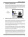
PRODUCT DESCRIPTION
The ASeries A700 MultiPort allows two computers to share the same
printer. It provides one Serial input port and one Parallel input port.
The A700 is connected to the parallel port of the printer and takes its
power from this port. Switching between the two input ports is fully
automatic but no buffering will occur.
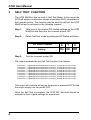
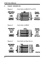
Figure 1
A700 MultiPort
2
INSTALLATION (Lexmark 23xx Series Printers)
Before installing the A700 MultiPort, please make sure that the DIP
Switches are set correctly to meet your requirements. Please refer to
Section 4 for complete details of the DIP Switch Settings.
Once the DIP Switches are set, the A700 may be simply hooked into
place on the rear of the Lexmark 23xx printer and the parallel output
connector plugged directly into the printer.
Turn the printer ON and observe the LEDs on the A700 MultiPort .
The ‘Power’ LED should light up and remain alight. The 'Data' LEDs
should light up and then extinguish within 2 seconds. After this
sequence the unit is ready for operation.
Power the printer OFF and connect the correct cables between the
A700 MultiPort and the host devices. Use only cables which you know
to have the correct pin configurations to match the A700 to your
equipment. Cable requirements are discussed in Sections 5 and 6.
WARNING: All devices must be powered OFF before connecting cables to them.
1
A700 User Manual
3
SELF TEST FUNCTION
The A700 MultiPort has an built-in Self Test Mode. In this mode the
A700 will output a continuous stream of printable ASCII characters to
the Lexmark printer. This function may be used to self test the A700
MultiPort and is activated in the following manner:
Step 1:
Take note of the original DIP Switch settings on the A700
MultiPort and then turn the Lexmark printer OFF.
Step 2:
Select ‘Self Test’ mode by setting the DIP Switch as follows:
DIP Switch Number
Setting
Step 3:
6
7
On On
8
Off
Turn the Lexmark printer ON.
The output produced by the Self Test function is as follows:
0123456789:;<=>?@ABCDEFGHIJKLMNOPQRSTUVWXYZ[\]^_’abcdefghijklmnopqrstuvwxyz{|}~
0123456789:;<=>?@ABCDEFGHIJKLMNOPQRSTUVWXYZ[\]^_’abcdefghijklmnopqrstuvwxyz{|}~
0123456789:;<=>?@ABCDEFGHIJKLMNOPQRSTUVWXYZ[\]^_’abcdefghijklmnopqrstuvwxyz{|}~
0123456789:;<=>?@ABCDEFGHIJKLMNOPQRSTUVWXYZ[\]^_’abcdefghijklmnopqrstuvwxyz{|}~
0123456789:;<=>?@ABCDEFGHIJKLMNOPQRSTUVWXYZ[\]^_’abcdefghijklmnopqrstuvwxyz{|}~
0123456789:;<=>?@ABCDEFGHIJKLMNOPQRSTUVWXYZ[\]^_’abcdefghijklmnopqrstuvwxyz{|}~
0123456789:;<=>?@ABCDEFGHIJKLMNOPQRSTUVWXYZ[\]^_’abcdefghijklmnopqrstuvwxyz{|}~
0123456789:;<=>?@ABCDEFGHIJKLMNOPQRSTUVWXYZ[\]^_’abcdefghijklmnopqrstuvwxyz{|}~
0123456789:;<=>?@ABCDEFGHIJKLMNOPQRSTUVWXYZ[\]^_’abcdefghijklmnopqrstuvwxyz{|}~
This output will continue as long as the printer is powered ON. To stop
the output simply turn the printer OFF.
Once the Self Test is complete, the A700 DIP Switches should be
returned to their original settings for normal use.
2
A700 User Manual
4
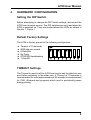
HARDWARE CONFIGURATION
Setting the DIP Switch
Before attempting to change the DIP Switch settings, disconnect the
A700 from its power source. The DIP switches are only read when the
A700 is powered on. They are located above the LEDs as shown in
Section 1, Figure 1.
Default Factory Settings
The A700 is factory pre-set to the following configuration:
l
l
l
l
l
l
Timeout of 10 seconds
9600 bits per second
8 Data Bits
No Parity
DTR/DSR Handshaking
1 Stop Bit
TIMEOUT Settings
The Timeout is used to tell the A700 how long to wait for data from one
port before switching to the other port. A Timeout of 10 seconds is
recommended for most applications and 20 seconds is recommended
for CAD, Windows and programs which tend to periodically pause
during printing.
3
A700 User Manual
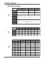
DIP Switch Settings
Switch
Function
OFF
ON
1
Timeout
20 sec
10 sec
2
Handshaking
DTR/DSR
Robust
Xon/Xoff
Table
4-1
3
4
Bits Per Second
(refer to Table 4-2)
5
6
Data Bits, Parity & Test Mode
Table 4-3)
7
(refer to
8
Table
4-2
Switc
300
600
1200
2400
4800
3
Off
On
Off
On
Off
On
Off
On
4
Off
Off
On
On
Off
Off
On
On
5
Off
Off
Off
Off
On
On
On
On
Switch
Table
4-3
4
9600 19.2K 38.4K
6
7
8
Data
Bits
Parity
Stop
Bits
Self
Test
On
On
On
8
Even
1
No
On
On
Off
8
None
1
Yes
On
Off
On
8
Odd
1
No
On
Off
Off
8
None
1
No
Off
On
On
7
Even
1
No
Off
On
Off
7
None
2
Yes
Off
Off
On
7
Odd
1
No
Off
Off
Off
7
None
2
No
A700 User Manual
5
CABLE REQUIREMENTS
Use Shielded Cable
Alfatron Pty Ltd recommends the use of shielded cable with all of its
products. Shielding reduces EMI radiation and improves noise
immunity. This will help to minimise interference to other equipment
and will improve the communications reliability.
The recommended cable construction is as follows:
(1) Take the shield (surrounding cable wires) and solder it to the Frame
Ground (FG) pin.
If FG is not available then connect the shield to Signal Ground
but, in this case, always use a separate wire to connect Signal
Ground at both ends.
(2) The shield must only be connected at one end of the cable and
must run the full length of the cable.
(3) We recommend connecting shield at the cable end which is not
attached to the A700.
5
A700 User Manual
6
6
CABLE EXAMPLES
Diagram 1.
Serial Cable for IBM PC/XT and PS/2
Diagram 2.
Serial Cable for IBM AT
Diagram 3.
Serial Cable for Other Devices
A700 User Manual
7
PORT PINOUTS
Centronics Parallel Port
Pin
1
2
3
4
5
6
7
8
9
10
11
12
13
14
15
16
17
18
Signal
Description
Pin Signal
Description
Data Strobe
Data Bit 1
Data Bit 2
Data Bit 3
Data Bit 4
Data Bit 5
Data Bit 6
Data Bit 7
Data Bit 8
Acknowledge
Busy
Paper End
Select
Autofeed
Not Connected
Ground
Ground
Not Connected
Active Low
Active High
Active High
Active High
Active High
Active High
Active High
Active High
Active High
Active Low
Active High
Pulled Low
Pulled High
Pulled High
-
19
20
21
22
23
24
25
26
27
28
29
30
31
32
33
34
35
36
Not Connected
Pulled High
Pulled Low
Ground
Ground
Ground
Ground
Ground
Ground
Ground
Ground
Ground
Ground
Ground
Ground
Initialize
Error
Ground
Not Connected
Not Connected
Select In
RS-232C Serial Port
The RS-232 Serial Port of the A700 MultiPort is configuired as DTE.
Pin
Status
Signal
Description
1
2
3
4
5
6
7
8
20
22
Used
Output
Input
Not used
Not used
Input
Used
Not used
Output
Not Used
FG
TD
RD
RTS
CTS
DSR
SG
DCD
DTR
RI
Frame Ground
Transmit Data
Receive Data
Request To Send
Clear To Send
Data Set Ready
Signal Ground
Data Carrier Detect
Data Terminal Ready
Ring Indicator
- Pulled High
- Pulled High
- Pulled High
- Pulled High
7
A700 User Manual
8
SPECIFICATIONS
CPU:
Parallel Ports:
Serial Port:
80C31 Microprocessor
Centronics Parallel
Input - 36-pin Centronics female connector
Output - 36-pin Centronics male connector
Asynchronous RS-232D
Full duplex communication
DB-25 female connector
DIP Switch Selection:
Baud Rate:
(bps)
Data Bits:
Parity:
Stop Bits:
Handshaking:
Flow Control Buffer:
LED Indicators:
Power Supply:
Dimensions:
60 byte receive buffer
Power On
Receive Data
Transmit Data
Data Error
(Yellow)
(Green)
(Green)
(Red)
5Vdc from printer parallel connector - Pin 18
154mm x 95mm x 13mm
Weight:
225 grams
Operating Temperature:
0° to 40° C
Stroage Temperature:
300, 600, 1200, 2400, 4800,
9600,19200 and 38400.
7 or 8
None, Odd or Even
1 or 2
Software (Robust Xon/Xoff)
Hardware (DTR/DSR)
-20° to 70° C
All specifications subject to change without notice
8