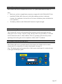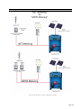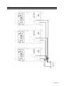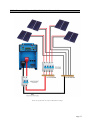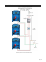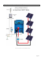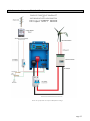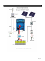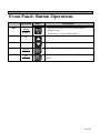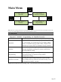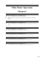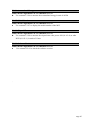
1
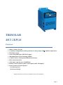
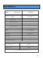
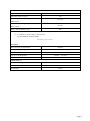
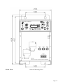
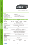
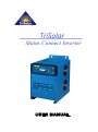
TRISOLAR MCI 2KW48 Features: Mains Connect Inverter Continuous Output Power Rating without de-rating at up to 50℃ ambient temperature. DC Battery input Solar, Wind and Hydro MPPT DC input* Maximum Power Point Tracking (MPPT), Combi Connect, offering True Hybrid interactivity. Direct feed connection Solar input capacity up to a 2400Watts. Remote control replica of main control panel with LCD display*. Power Stack for increased power - Need more power? Just keep stacking! *Requires optional accessories, please see installation section for more information. Page 5 About TriSolar Mains Connect Inverter: Introduction The TriSolar MCI can operate as a true Hybrid power system were power produced from your solar panels, wind generator or hydro system can be sent back into the grid for a credit, however, authorisation from your electricity provider is required. The system can also operate as a standalone power system, allowing you to power your home during a grid failure or for an independent “Off-Grid” setup. Alternatively, for “Off-Grid systems, a backup generator can be automatically started to help support the homes power needs. The TriSolar MCI is a highly reliable Mains Connect Inverter and its most critical feature is to maximise the harvest energy from the PV array by using the advanced technology of Maximum Power Point Tracking (MPPT). The TriSolar MCI can also be directly connected to a battery allowing for even more flexibility. The system is available in models 48VDC nominal battery voltage inputs each have built-in programmable protection to ensure the correct battery connection and disconnection voltages to avoid exhausting the battery. A wide range of MPPT input array voltages and battery voltage inputs are available depending on your application. The DC input of MCI 2KW48 may be wired in the range of 66-128VDC or nominal battery voltage of 48VDC. TriSolar MCI may not only be used in solar systems but also in wind or hybrid systems. With respect to these systems it is normally required to use an optional turbine controller. The controller with optional rectifier and braking unit for wind system is required to control and stop the control from overload condition caused by excessive wind speeds. TriSolar MCI is very flexible and can be configured in many different ways. It has been designed to operate as a standalone basic grid feed, through to a truly interactive hybrid power management system. The power being generated from the solar Array, wind or hydro is fed into the TriSolar MCI where it is then transferred into an AC supply. The hybrid design allows you to operate your home during a black out and take advantage of the power being generated from the solar array unlike many conventional Mains Connect Systems. This offers home owners and businesses even more savings on their electricity bills as well as the comfort of having power during a black-out. Please carefully read through this manual and all the installations instruction and wiring before beginning installation of your TriSolar MCI. The protection and installation equipment must comply with the local codes. The rated fuses, breakers and external lightning protection should be installed along with your TriSolar MCI. Page 6 Specifications MODEL 48 Volt System Ventilation MCI 2KW48 Fan Forced cooling Temperature – Operation -10℃~ +45℃ – Storage -25℃~ +80℃ Protection a. Output short circuit b. Over load c. Battery voltage too high d. Battery voltage too low e. DC input voltage too high f. DC input voltage too Low Transformer (105℃) Electronic & Powerstage (70℃) Humidity 0~95% (non condensing) Combi Connect Direct Feed Anti-Islanding (less than 10 msec) Direct Battery Connection 3-Phase Capacity Parallel Operation Remote Control Port Extension Port for PC Connection AC OUTPUT Output Voltage Cont. Power Output 210-255V @ 50℃ (W) 2000Watt Under 50℃ (cosθ=1.0) (No derate 50℃ ) Power Output Over 70℃ (Shutdown) Maximum Power (W) Maximum Efficiency (%) 2200Watt 94 Please note specifications are subject to Manufactures changes. Page 7 DC INPUT Maximum DC Input Voltage (VDC) 130V Maximum Input Current(A) 45A Input Voltage operating Range (VDC) 66-128V MPPT Mode Input Voltage operating Range (VDC) 40-64V Battery Mode Battery Voltage Default (VDC) (1) 48V X should be 2, output voltage = 205-270 VAC Eg. MCI 2KW48= 230VAC Model Specifications subject to change AC INPUT Detection Time AC Input Fault <10 msec. Normal AC Input Range 210VAC – 255VAC Trip Level AC Low Input 209VAC 230v Model Trip Level AC High Input 255VAC 230v Model Min.~ Max. Frequency Range 50 ± 1 Hz / 60 ± 1 Hz 230v Model MECHANICAL Cabinet / Protecting Class Dimension (HXWXD) Weight (kgs) Aluminum / IP20 368 x 256 x 424 mm 26 kgs Page 8 Front View Backside Mounting Holes Page 11 1.25 3-Phase Operation The TriSolar MCI can be configured for use in a 2 or 3-phase applications see page 32. Note: Make sure you have enough battery capacity to support all of the TriSolar MCI Units. Install the TriSolar MCI units next to each other making sure there is adequate clearance for ventilation of at least 20 cm. For better ventilation, please install the fan cover (optional). The battery cables for each TriSolar MCI must be of equal in length 1.26 Anti-Islanding The TriSolar MCI inverter will automatically disconnect from the utility grid when the utility grid is out of voltage / frequency range, during a black-out (grid failure) or when the inverter shuts down due to a fault condition. This is to guarantee protection for persons operating on the utility grid, and in compliance with the AS4777 standards. 1.27 Remote Control Panel (RP-MCI) The TriSolar MCI can be operated remotely from remote port with the aid of a remote control panel. For connection of a remote control panel, see page 29. Note: The display panel and operation flow of the remote control panel is exactly the same as the upper-front display panel. Page 25 2.12 Diagram Net vs Gross Metering Please note specifications are subject to Manufactures changes. Page 28 Chapter 3 Wiring Connections 3.10 Lower-Front Panel Connection for TriSolar MCI A H B C D G F E Connections / Lower- Front side A B C D E F G H PORT A (IN) PORT B (OUT) PORT C (EXT) AC Output Breaker AC OUT E AC OUT N AC OUT L Battery POS+/ NEG- Connections for parallel power Connections for parallel power Connections for external Remote Control & PC Mains AC output Circuit Breaker Connecting terminal for AC output Ground (Earth) Connecting terminal for AC output Neutral (NEG) Connecting terminal for AC output Live (POS) DC Input cables. Page 29 3.11 Battery Connection schematic Page 30 3.12 Connection Schematic “Multi Cable Solar Connection” Please note specifications are subject to Manufactures changes. Page 31 3.13 AC 3-Phase Connection Schematic Please note specifications are subject to Manufactures changes. Page 32 3.20 Connection Schematic (Basic Solar Grid Feed) Please note specifications are subject to Manufactures changes. Page 34 3.21 Connection Schematic (Wind Grid Feed) Please note specifications are subject to Manufactures changes. Page 35 3.22 Connection Schematic (Hydro Grid Feed) Please note specifications are subject to Manufactures changes. Page 36 3.23 Connection Schematic (Battery Mode Grid Feed) Please note specifications are subject to Manufactures changes. Page 37 Chapter 4 Operation 4.10 Front Panel Display 9 2 8 7 1 5 3 6 4 PB1 PB5 PB2 PB4 PB3 The POWER “rocker” switch (9) is the Master ON / OFF Switch. This switch in the “OFF” position will terminate all functions of the TriSolar MCI. NOTE: The AC Output is turned OFF when the inverter is Switched OFF at the Master Power Switch. Page 38 4.10 Front Panel Display LED Indicators LED Name LED ON 1 BATTERY MCI is operating in Battery Mode 2 MPPT DC INPUT MCI is operating in MPPT Mode 3 LCD Display Display user information AC Grid is stable and within the Voltage & frequency settings. 4 AC GRID FEED 5 COMBI GRID Green: Power is being sent to the Combi-Grid 6 POWER MASTER Power Switch AC GRID Yellow: Power is being used from the Mains Grid to support AC Load. (Mains AC power plus the Combi Inverter power and the MCI’s power is being used). . COMBI Green : CombiNet connection is active Red: CombiNet Connect is lost. (check cable or reboot system) AC LOAD Yellow: TriSolar MCI is supplying power to the Combi-Grid to support the Combi. 7 8 9 LED OFF No AC Grid (Blackout) Flashing: AC Grid voltage or frequency is checking. Disconnected from Combi-Grid No AC Grid (Blackout) Combi Not Connected or wrong communication settings There is NO AC output to the load Page 39 4.20 Front Panel Button Operations Front Panel: Button Operations Push buttons PB1 MENU Arrow < Name Description 1. Function Key to move Cursor to the left digit at Parameter Edit. 2. Function key to return to Main Menu. △ Increment key to edit Parameter value. PB2 UP (△) PB3 DOWN (▽) ▽ Decrement key to edit Parameter value. PB4 DATA ENT Function Key to edit Data value and Data write-in key PB5 ESC RESET Returns to the status before the DATA/ENTER key was pressed. Page 40 Main Menu Press *** Main Menu *** Operation *** Main Menu *** Modified Constants Press Press *** Main Menu *** Initialize *** Main Menu *** Programming Press Note: After the set time period (01-02: Key Idle Detect Time) the system will exit any menu MCI screens and return to the standby display (01-01: Power ON LCD Monitor Select). 4.30 Main Menu There are four options in the Main Menu of the “TriSolar MCI” and they are “Operation”, “Initialize”, “Programming” and “Modified Constants”. Function Content Operation “TriSolar MCI” can monitor Operation Status, Output Watts, AC-Grid Voltage, AC-Grid period, DC-IN voltage, Output current, accumulated energy, model number, Elapsed Time and Software Version. This is U (Monitor Group) constants. Initialize Operation Condition Setting Group A (Initialize) Group: constants initialization setting and constants modification allowed/prohibited setting. Programming Constant groups to program (modify) all the constants: B (General) Group, O (Operator) Group, and PC communication Group Modified Constants Operating the read-out and modification of the constants group setting which are different from initial setting. Users can program and modify constants Note: On any Menu Screen, pressing “ESC” key will return you to the previous Menu. Page 41 4.40 Main Menu :Operation “Monitor” Main Menu: Operation “Monitor” U1-00: Operation Status Main Menu>Operation>ENT>Monitor>ENT> Use U1-00 to monitor the current status of the MCI, Waiting, MCI Fault, Grid Fault, No Utility, MCI OH (Over Heat), Grid Check, Normal. U1-01: Output Watts Main Menu>Operation>ENT>Monitor>ENT> Use U1-01 to monitor the current output wattage value of AC power out in units of 0.1W. U1-02: AC-Grid Voltage Main Menu>Operation>ENT>Monitor>ENT> Use U1-02 to monitor AC IN voltage value in units of 0.1V. U1-03: AC-Grid Frequency Main Menu>Operation>ENT>Monitor>ENT> Use constant U1-03 to monitor AC IN Frequency value in units of 0.1Hz. U1-04: AC OUT Current Main Menu>Operation>ENT>Monitor>ENT> Use constant U1-04 to monitor DC-IN voltage value in units of 0.1V. U1-05: Output Current Main Menu>Operation>ENT>Monitor>ENT> Use constant U1-05 to monitor the output current value in units of 0.01A Page 42 U1-06: Accumulated Energy Main Menu>Operation>ENT>Monitor>ENT> Use constant U1-06 to monitor the accumulated energy in unit of 1kWh. U1-07: Model Number Main Menu>Operation>ENT>Monitor>ENT> Use constant U1-07 to display the model number of the MCI. U1-08: Elapsed Time Main Menu>Operation>ENT>Monitor>ENT> Use constant U1-08 to monitor the elapsed time after power ON (O1-03=0) or after RUN (O1-03=1) in units of 1 hour. U1-09: Software Version Main Menu>Operation>ENT>Monitor>ENT> Use constant U1-09 to check the software version. ` Page 43