1
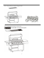
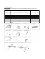
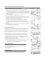
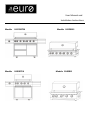
User Manual and
Installation Instructions
Model:
: EA120BTSX
Model:
: EA90BTSX
Model:
:EA120BIS
Model:
:EA90BIS
For Outdoor use only.
Read the instructions carefully and be sure your barbecue is properly installed, assembled and cared for.
Failure to follow these instructions may result in serious bodily injury and/or property damage.
Please retain the manual for future reference.
These BBQs are configured for use with Propane Gas, however are also approved for use with Natural Gas. If
you prefer to connect the BBQ to Natural Gas, the BBQ needs to be configured for Natural Gas. Converting
this BBQ to Natural Gas must only be done by an authorized person and with a Natural Gas conversion kit
supplied by Eurostyle. Please contact Eurostyle to purchase a Natural Gas Conversion kit.
Remove any transit protection before using.
Please DO NOT use the two solid hot plates together.
NOTE TO INSTALLER: TEST OPERATION OF THE APPLICANCE AND INSTRUCT THE USER BEFORE LEAVING.
Service & Spare parts
Your appliance should be serviced annually by a competent authorised person
For serving or spare parts or Natural Gas conversion kit, please contact
Eurostyle Group trading as Euro Appliances
Service line: (08) 81651012
Fax: (08) 8165 1018
Email: [email protected]
2
USE OUTDOORS ONLY
This appliance shall only be used in an above ground open-air situation with natural ventilation, without stagnant areas,
where gas leakage and products of combustion are rapidly dispersed by wind and natural convection.
Any outdoor enclosure or alfresco area in which the appliance is used shall comply with one of the following:
l
An enclosure with walls on all sides, but at least one permanent opening at ground level and no overhead cover. See
Figure 1.
l
Within a partial enclosure that includes an overhead cover and no more than two walls. See Figure 2 & 3.
l
Within a partial enclosure that includes an overhead cover and more than two walls, the following shall apply:
- At least 25% of the total wall area is completely open; and
- At least 30% of the remaining wall area is open and unrestricted. See Figure 4 & 5.
l
In the case of balconies, at least 20% of the total of the side, back and front wall areas shall be and remain open and
unrestricted.
The following diagrams provide a diagrammatic representation of outdoor areas. Rectangular areas have been used in these
figures - the same principles apply to any other shaped area
Figure 1 - Enclosure with walls on all sides but
Figure 2 - Partial Enclosure with overhead cover and
no overhead cover
no more than two walls
Figure 3 - Partial Enclosure with overhead cover and
Figure 4 - Open side at least 25% of total wall area.
no more than two walls
30 % or more in total of the remaining wall area is
open and unrestricted.
Figure 5 - Open side at least 25% of total wall area. 30 percent or more
in total of the remaining wall area is open and
unrestricted
3
DO
* Use spanner to tighten all gas fittings
* Check all gas hose and line connection for
damage, cuts or cracks each time for using
the appliance.
* Always leak test with soapy water
*Check main burners, side burners and
infrared rear burner regularly for spider webs
and insect nests as these may interfere with
the proper operation of the burners and must
be removed before using the burners.
* Use the appliance outdoors only
* Accessible parts maybe very hot. Always
Keep children away from the appliance
*Have the gas cylinder filled by an authorized
gas supplier
* Always wear protective gloves when
handling hot component
* Close the gas cylinder valve after each use
* Clean the grease tray regularly.
* USE grill at least 915mm from any
combustible, wall or surface.
* “Burning off” the barbecue after every use
(for approx 15 minutes) will keep excessive
food residue to a minimum.
* Turn off the gas supply at the cylinder in the
event of gas leak.
Do not do
* Do not lean over appliance when lighting
* Do not store combustible materials, gasoline,
flammable liquids or vapors within vicinity
of barbecue
* Do not use appliance with any cover on
* Do not use plastic or glass utensils on the
Barbecue
* Do not use the appliance in strong winds
* Do not dismantle control valves
* Do not test for gas leaks with a naked flame
* Do not store spare gas cylinders in the
cabinet
* Do not lay the gas cylinder down ( always
keep upright)
* Do not use appliance indoors
* Do not modify the construction of the
appliance or the size of any burner, injector
orifice or any other components
* Do not move the appliance during use
* Do not obstruct any ventilation of the
appliance
* Do not allow the flexible gas supply hose or
any electrical cord to come in contact with any
heated surface of the appliance
* Do not use charcoal or any other solid fuel in
this appliance
* Do not disconnect any gas fittings while the
appliance is in use
* Do not use a rusty or dented gas cylinder
with a damaged gas valve
* Do not fill the gas cylinder beyond 80%
capacity
* Do not use the infrared rear burner at the
same time as other burners
4
Gas Cylinder Information
Gas Cylinder Safety Information
• This appliance is designed to be used with a gas cylinder not exceeding 9KG.
• The gas cylinder supply valve must be turned off when the appliance is not in use.
• Gas cylinders must be stored outdoors, out of reach of children and must not be stored in a building, garage or any
other enclosed area.
• The gas cylinder used must incorporate a safety collar to protect the valve assembly.
* Never store a spare cylinder under the barbecue shelves or inside the trolley housing. Any
LPG cylinder not attached to the BBQ for use should be stored outdoors and well away from this appliance.
Important:
• When disconnecting and removing the gas cylinder for the purpose of refilling, always observe the following
procedure.
• Ensure that all gas control valves on the appliance and the gas cylinder are turned off before disconnecting the
regulator from the cylinder.
• Do not smoke or use a naked flame near the appliance or gas cylinder while disconnecting the gas line between the
appliance and gas cylinder.
• Remove the gas cylinder from the enclosure before disconnecting the regulator from the appliance.
• Tighten all connections before placing the gas cylinder back in its enclosure.
• The gas leak testing procedure should be conducted every time the gas cylinder is refilled and reconnected to the
appliance before using the appliance.
Regulator Connection
1. Check that all control knobs are in the ‘Off’ position.
2.
Make sure the cylinder valve is off.
3.
Remove the protective cap from the cylinder if present.
4. Leak test the connection with a soapy water solution.
Gas Leak Test Procedure
Never use a naked flame to check for gas leaks. Always use the following procedure to check for gas leaks.
1.
In a small container, mix up a solution of water and detergent or soap. Mix the solution well.
2. Make sure that the gas supply valve on the gas cylinder is turned on.
3.
Make sure that the gas control valves on the appliance are all turned off.
4. Using a brush or spray bottle apply the solution to the gas line and each join in the gas line.
5. Bubbling of the solution will indicate that there is a leak present.
6.
Re-tighten or re-seal any joints that are leaking.
7.
If a leak persists then contact your distributor or the manufacturer for assistance.
5
LIGHTING YOUR BARBECUE
This barbecue is designed for use outdoors, keep away from any flammable materials.
It is important that there are no overhead obstructions and that there is a minimum distance of 915mm from the side or
rear of the appliance. Do not use the BBQ under overhead combustible materials.
It is important that the ventilation openings of the cylinder compartment are not obstructed.
The barbecue must be used on a level, stable, non-flammable surface.
The appliance should be protected from direct draughts and shall be positioned or protected against direct penetration by
any trickling water (e.g. rain). Parts sealed by the manufacturer or his agent must not be altered by the user.
No modifications should be made to any part of this barbecue and repairs and maintenance should only be carried out by
an authorized person.
DO NOT let children operate or play near grill.
DO NOT use charcoal or ceramic briquets in a gas grill
DO NOT light or use the side burner with the lid in the closed position.
DO NOT attempt to light burner with lid closed. A build-up of non-ignited gas inside a closed grill is hazardous
The side burner is designed for pot/pan with diameter 60-260mm. Side burner lid can not be
used as work table, do not put anything on the side burner lid.
Lighting Instruction:
1. Read instructions before lighting.
2. Open the lid and make sure all the knobs are on the OFF(
) position.
3. Connect the regulator to gas cylinder and the hose to barbecue. Turn the gas supply “ON” at the cylinder. Check with
the use of soapy water for any gas leakage between the bottle and the regulator.
4. Push down the control knob and keep pressing whilst turning anti-clockwise to HIGH (
) position whilst also pressing
the ignition button (a clicking sound is heard), this will light the burner.
5. If the burner still does not light, turn the control knob to OFF(
) wait 5 minutes and repeat step 4. If the burners do
not stay alight , repeat steps 4 and 5.
6. Adjust the heat by turning the knob to the High (
)/Low (
6
) position.
7. To turn the barbecue ‘OFF’ turn the cylinder valve to the ‘OFF’ position and then turn all
of the control knobs on the appliance clockwise to the OFF (
) position.
For Infrared rear burner
Push down the control knob and keep pressing whilst turning anti-clockwise to HIGH (
) position and also pressing the
ignition button (a clicking sound is heard). After the infrared rear burner is lit, keep pushing down the control knob and hold
for 5 seconds. It may take a little while for the gas to flow to the infrared burner because it is some distance away from
the gas valve.
For Match- Lighting:
1. Follow above instruction step 1-3.
2. For Main burner, place the match into match lighting stick
and light the match, then put into lighting hole on right
side of the barbecue; For burners far away from right side
of the barbecue, take the cooking grate out and place the
match near the main burner ports;
For side burner, place the lit match on the holes of the
side burner head,
For infrared rear burner, place the lit match on the
surface of ceramic panels
) position. Thus the burner could be lit. If the burner does
3. Push down and turn the knob anticlockwise to HIGH(
not light, turn off the gas tap and wait for 5 minutes then repeat this step 2-3.
Before cooking for the first time, operate the barbecue for about 15 minutes with the lid closed and the gas turned on
HIGH(
). This will “heat clean” the internal parts and dissipate odor from the painted finish. The color of cooking area
may slightly discolour. This is normal and it is the nature of material.
While igniting main burner and infrared rear burner, please make sure the lid for main burner is in open position
While igniting side burner, please make sure the lid for side burner is in open position
Battery Replacement:
Unscrew the battery cap and plastic nut on the igniter
at the front of the control panel. Replace the battery
and refit the cap.
7
CLEANING AND CARE
All cleaning and maintenance should be carried out when the barbecue is cool and with the fuel supply turned OFF at the
gas cylinder.
DO NOT mistake brown or black accumulation of grease and smoke for paint. Surfaces of the gas grills & hotplates are not
painted. Apply a strong solution of detergent and water or use a grill cleaner with scrubbing brush on insides of
grill lid and bottom. Rinse and allow to completely air dry.
DO NOT apply a caustic grill / oven cleaner to any painted surfaces.
DO NOT use abrasive or flammable cleaners, as it will damage the parts of the product and may start a fire.
Plastic parts: wash with warm soapy water and wipe dry.
Porcelain surfaces: because of glass-like composition, most residue can be wiped away with backing soda / water solution
or specially formulated cleaner. Use nonabrasive sourcing powder for stubborn stains.
Painted surfaces: wash with mild detergent or nonabrasive cleaner and warm soapy water. Wipe dry with a soft
nonabrasive cloth.
Stainless steel surfaces: Stainless steel will surface rust if not maintained well. To maintain your grill’s high quality
appearance, wash with mild detergent and warm soapy water and wipe dry with a soft nonabrasive cloth after each use.
Use stainless steel protection liquid like WD-40 on the surface to avoid rust.
Cooking grid: Use a mild soapy water solution. Non-abrasive scourer can be used on stubborn stains then rinse with
water.
Abnormal Operation:
Any of the following are considered to be abnormal operation and may require service
Yellow tipping of the yellow flame
Sooting up of grills plates
Burners not igniting properly
Burners failing to remain alight
Burner extinguished by trolley doors
Gas valves, which are difficult to turn
8
Technical Information
Model No.:
EA120BTSX/CB6-SBG001-BU
EA120BIS/CB6-BG001(B)
Test Point Pressure:
2.75KPA
2.75KPA
Total Nominal
Gas Consumption:
96.1 MJ/h
81.1 MJ/h
Gas Type:
Propane
Propane
Nominal gas consumption:
Main Burners: 11.6 MJ/h x 6
Side Burner: 15MJ/h
Back Burner: 11.5MJ/h
Main Burners: 11.6 MJ/h x 6
Back Burner: 11.5MJ/h
Injector Size:
Main Burners: 0.98mm
Side Burner: 1.13mm
Back Burner: 1.00mm
Main Burners: 0.98mm
Back Burner: 1.00mm
Model No.:
EA90BTSX/CB4-SBG001-BU
EA90BIS/CB4-BG001(B)
Test Point Pressure:
2.75KPA
2.75KPA
Total Nominal
Gas Consumption:
72.9 MJ/h
57.9MJ/h
Gas Type:
Propane
Propane
Nominal gas consumption:
Main Burners: 11.6 MJ/h x 4
Side Burner: 15MJ/h
Back Burner: 11.5MJ/h
Main Burners: 11.6 MJ/h x 4
Back Burner: 11.5MJ/h
Injector Size:
Main Burners: 0.98mm
Side Burner: 1.13mm
Back Burner: 1.00mm
Main Burners: 0.98mm
Back Burner: 1.00mm
AGA Approval No.:
AGA 7142 G
For Use outdoors and in well ventilated areas
Warning: Accessible parts may be very hot, keep young children away.
Close the valve of the gas cylinder or the regulator after use.
The use of this appliance in enclosed areas can be dangerous and is prohibited
For storage and cylinder exchange, disconnect the cylinder only. Do not disconnect hose from the
appliance.
Always maintain 915mm minimum clearance to combustible materials at the rear and sides of
the BBQ. Do not use this BBQ under overhead combustible surfaces.
Conversion to natural gas only to be done by authorized person.
The minimum cylinder size for use with this appliance is 7kgs
The thread type of this appliance is G1/4B.
9
Exploded View
Model No. : EA120BTSX
10
Exploded View
Model No. : EA120BIS
11
Exploded View
Model No. : EA90BTSX
12
Exploded View
Model No. : EA90BIS
13
ASSEMBLY STEPS
Tools required:
1.Attach left side table as shown in the diagrams below.
. On each side of the BBQ there are 2 preassembled screws; Loosen them to 4mm of thread showing.
. Hang the side table onto these loose screws on each side
. Assemble 3pcs of M6X15 screws in 2 lower holes.
. Tighten all screws.
14
2. Connect side burner
1) Take out side burner grid
2) Loosen the screws which secure the side burner with Philips head screwdriver and take it out.
3) Assemble the side valve, meanwhile put the knob seat on front panel and tighten the two screws together
with knob seat and side valve.
15
4) Put back side burner and tighten the screws, meanwhile put the side burner inlet into side
valve injector.
16
5) Connect the side burner ignitor.
6) Put back side burner grid.
3. Attach left side table as shown in the diagrams below
1) Assemble the table and front panel with 3pcs of M6X10 and M6
2) Attach left side table
. On each side of the BBQ there are 2 preassembled screws; Loosen them to 4mm of thread
showing.
. Hang the side table onto these loose screws on each side
. Assemble 3pcs of M6X15 screws in lower holes.
. Tighten all screws.
17
4.
.Fit flame diffusers as shown in diagram below.
5.
.Fit cooking grids and plate as shown below
Please DO NOT use two hot plate together.
18
6.
.Fit warming rack as shown below
.
7.
.Unscrew cap and place AA Battery into place with the (+) end facing outwards. Screw cap back on. Upon
pressing the ignition button, you will hear a clicking noise if it has been installed correctly.
AA battery is not provided
19
For Outdoor Built-in BBQ
EA120BIS & EA90BIS
1.
Assemble the side bracket
2. Fit flame diffusers as shown in diagram below.
20
3. Fit cooking grids and plate as shown below
Please DO NOT use two hot plate together.
4. Fit warming rack as shown below
21
Barbecue Dimensions for inbuilt models
EA120BIS
EA90BIS
22
Guide for building-in
Warning: Contact your local municipality for any building codes regulating the installation of
outdoor barbecue appliances. Outdoor installations must conform to local codes or, in the
absence of local codes, with AS5601 - Gas Installations.
THE CONSTRUCTION OF THE ENCLOSURE AND INSTALLATION OF THE BBQ SHOULD BE CARRIED
OUT ONLY BY AUTHORISED PERSONS.
The BBQ must be placed on a construction made from non-combustible materials which must
support the full weight of the BBQ.
For Propane installations, the BBQ must be separated from the LPG cylinder and there must be
enough room so that the cylinder can stand upright.
THE BARBECUE MUST ALSO BE SECURED TO THE ENCLOSURE TO PREVENT IT BEING PULLED
OUT AND STRAINING THE GAS CONNECTIONS.
Ventilation
Ventilation must be in accordance with AS5601 - Gas Installations. In general, the appliance
should have adequate ventilation for complete combustion of gas, proper flueing and to
maintain temperatures of immediate surroundings within safe limits. The air that the BBQ
requires for proper combustion enters through both sides of the BBQ. The construction of the enclosure
must provide an unobstructed air supply via a minimum of 260cm2 on both sides.
23
Clearances
Allow adequate clearance on the right and left side of the BBQ so that the rotisserie motor and
skewer (where supplied) can be removed. Ensure there is at least 100mm clearance at the rear
so that the hood can be opened without obstruction. Allow a minimum clearance of 10mm
from the sides and rear of the BBQ to any non-combustible construction located below the BBQ
cooking surface.
Any combustible materials must be at least 915mm away from the sides and rear of the BBQ.
Do not use the BBQ under overhead combustible surfaces. Do not obstruct the ventilation air
openings around the structure.
24
For rotisseries kit
The side burner is not allowed to operate during operation of turnspit motors
PARTS
Description
Quantity
A
Rotisseries Motor AC / Motor DC
1
B
Bolt and Nut
2
C
Motor Bracket
1
D
Spit Rod collar
1
E
4-Sprong Meat Fork
2
F
Spit Rod
1
G
Collar
1
H
Weight Balance (Counterweight)
1
I
Handle
1
J
Washer
2
25
ASSEMBLY, INSTALLATION AND OPERATION INSTRUCTIONS.
Assembling and Attaching Rotisseries Kit to barbecue
1. Using 2 sets of bolts, nuts and washers provided, attach the bracket
to the right side of the grill as shown in Fig 1 by passing two bolts through
the bracket and then the outside of your grill. Place a washer on the end
of each bolt. Secure bolts with nuts. Take care not to over tighten the bolts.
Repeat for right side.
2. Slide rotisseries Motor over right side Bracket.(Fig 2,3.)
3. Place the collar, Spit Rod collar and meat prongs onto the rotisserie rod
and attach it to the support on the right-hand side of the rotisserie bracket
on the grill . The rod should turn smoothly. (Fig 4.)
4. Place washer onto the rotisserie rod, followed by the weight balance.
Then attach the handle into the rotisserie rod. The weight balance
should be positioned in the space between the washer and handle of the rod
(Fig 5,6.)
6. Place the end of the rotisserie rod into the motor. Make sure rotisseries rod
is aligned properly with the motor. (Fig 7.)
Using the Rotisserie burner.
Plug the unit into an electrical outlet. Slide one of the meat prongs onto
the rod (prongs toward the food). Center the food to be cooked on the rod,
followed the thumbscrews. It may also be necessary to wrap food with
butcher’s string,(never use nylon or plastic string) to secure loose portions.
Once the food is secure, insert the pointed end of the rotisserie rod into
the motor assembly and rest the other end on the support on the right
hand side of the grill. If needed remove the cooking grates for more room.
Turn the power switch to the “ON” Position to start the rotisserie motor.
Turn the power switch off after cooking
Notes: When using the rotisserie burner, make sure all main burners are off.
When using the rotisserie burner, it is not recommended to use
Side burners as injury may result from burning.
1..
2..
3.
4.
5.
6.
CARE AND MAINTENANCE.
Turn off , unplug and remove the rotisserie kits when not in use.
After using, clean all metal parts using a dry cloth to avoid rusting.
Do not immerse any parts in water.
Store in a dry place.
7.
TROUBLESHOOTING
If the rod is not rotating at a constant speed, reposition the meat
on the forks and rod to adjust the weight so that it is balanced.
26