1
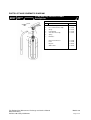
FIRE EXTINGUISHER
MAINTENANCE AND RECHARGE
SERVICE MANUAL
MODEL 150
1.5 kg Dry Chemical Powder Fire Extinguisher
*** RECHARGE EXTINGUISHERS IMMEDIATELY AFTER USE ***
All fire extinguishers should be installed and maintained in accordance with the relevant standards (AS
2444 and AS 1851) and the requirements of all authorities that have jurisdiction in relation to fire
extinguishers.
When maintenance is indicated, it should be performed by trained persons using proper equipment. Fire
extinguishers are pressure vessels and must be treated with respect and handled with care. They are
mechanical devices and require periodic maintenance to be sure that they are ready to operate properly
and safely.
Extinguishers should be serviced only with original and genuine spare parts – the use of substitute parts
constitutes the void of any warranty covering the equipment.
TROUBLE SHOOTING GUIDE
Warning :
Determine the source of a leak before the extinguisher is depressurized. The extinguisher
must be completely depressurized before any attempt is made to devalve it to correct any
leakage problem. To depressurize hold the extinguisher in an inverted position, hold
discharge hose and squeeze the discharge lever, be careful a small amount of agent will be
discharged. Thoroughly clean all valve parts after depressurizing and valve removal.
Problem
Corrective Action
Leak at Collar O-Ring
Remove valve assembly, clean wing nut thoroughly and install new
collar O-Ring. Lubricate O-Ring with Visilox V-728.
Leak through Valve
Install new valve stem assembly. Check valve seat for scratches or
foreign matter.
Leak around Gauge threads
Remove Gauge and reinstall using Teflon tape on Gauge threads.
Defective Gauge
Remove defective Gauge and install new Gauge using Teflon tape
on the Guage threads.
Leak in Cylinder
Discard and Replace cylinder
Fire Extinguisher Maintenance Recharge and Service Manual
Matal Consulting
PO Box 340 Oatley NSW 2223
Model 150
Page 1 of 4
PARTS LIST AND SCHEMATIC DIAGRAM
Model
150
1.5 Kg ABE Dry Chemical Powder
Extinguisher
Parts List
Item
Description
Part No.
1
Valve Assembly
L-01510
2
Hose and Nozzle Assembly
L-01520
3
Gauge
L-01030
4
Collar O-Ring
L-01040
5
Valve Stem Assembly
L-01050
6
Spring
7
Downtube
Metal Vehicle Bracket
L-01590
Label
L-01599
Ring Pin
L-04000
ABE Powder
L-05025
Fire Extinguisher Maintenance Recharge and Service Manual
Matal Consulting
PO Box 340 Oatley NSW 2223
Model 150
Page 2 of 4
INSPECTING THE EXTINGUISHER
This extinguisher should be inspected at regular intervals (Monthly or more often if circumstances dictate)
to insure that it is ready for use. Inspection is a quick check that an extinguisher is available and will
operate. Inspection is completed by seeing that the extinguisher is located in its designated place and
has not been actuated or tampered with, and that there is no obvious physical damage or condition to
prevent operation.
MAINTENANCE PROCEEDURE
Fire Extinguishers need to be maintained in accordance with the relevant standards AS 1851.
Maintenance is a thorough check of the extinguisher. It includes a thorough physical examination and
any necessary repair or replacement.
1. Clean Extinguisher to remove dirt, grease or any foreign material. Check to make sure that the
instruction Label is securely fastened and legible. Inspect the cylinder for corrosion, abrasion,
dents or weld damage. If damage is found to cylinder hydrostatic testing of the cylinder should
be carried out to determine if it can continue to be in service or if replacement is necessary.
Note: when cleaning avoid the use of solvents around the face of the pressure gauge. They
could seriously damage the plastic gauge face.
2. Inspect the extinguisher for damaged, missing or substitute parts.
approved for use.
Only genuine parts are
3. Weigh extinguisher and compare with weight printed on the label.
weight does not agree with the weight on the label.
Recharge extinguisher if
4. Check the date of manufacture on the extinguisher. Extinguisher must be hydrostatically tested
every 5 years to the test pressure indicated on the label.
5. Visually inspect the pressure gauge :
a. If bent, damaged or improper gauge, depressurize and replace.
b. If pressure is low, check for leaks.
c. If over pressurized (overcharged), reduce to correct pressure and check for leaks.
6. Remove hose and nozzle assembly and visually inspect inside valve body. Chemical in the valve
body may indicate that the extinguisher has been partially discharged and should therefore be
recharged. Inspect hose and nozzle for blockage or damage – replace as necessary. Blow air
through nozzle or discharge hole to ensure passage is clear of foreign material.
7. Inspect the valve assembly for corrosion or damage. Replace valve assembly or component
parts as necessary. If valve removal is necessary, complete all steps in the Recharging
Procedure.
8. Install Hose and nozzle assembly.
9. Install ring pin and new tamper seal and record service data on the extinguisher inspection tag.
10. Replace the extinguisher in the proper location. Make sure extinguisher fits the bracket properly
– install new bracket if necessary.
Fire Extinguisher Maintenance Recharge and Service Manual
Matal Consulting
PO Box 340 Oatley NSW 2223
Model 150
Page 3 of 4
RECHARGE PROCEDURE
Recharging is the replacement of the extinguishing agent and also includes the expellant.
Warning : A. Before attempting to recharge be sure this extinguisher is completely depressurized.
B. Use a regulated pressure source.
C. Check and calibrate regulator gauge at frequent intervals, the regulator gauge should be
used to determine when the intended charging pressure has been reached, do not use
the extinguisher gauge for this purpose.
D. Never leave an extinguisher connected to a regulator of a high pressure source for an
extended period of time. A defective regulator could cause the cylinder to rupture due to
excessive pressure.
1. Complete the Maintenance Service Procedure Steps 1 to 8.
2. Empty extinguisher of all remaining pressure and extinguishing agent.
3. Remove valve assembly and disassemble by removing downtube, spring and valve stem
assembly. Remove any collar O-Ring from the valve from the cylinder.
4. Thoroughly clean all parts. Blow the valve out with air or nitrogen. Inspect the collar O-Ring,
valve stem, and spring – replace as necessary. Lubricate the collar O-Ring, and small O-Ring on
the valve stem assembly with Visolox V-728. Do not lubricate the valve stem seal. Inspect the
downtube. If it is cracked, deformed or does not have a threaded brass spring retainer – replace.
Inspect downtube O-Ring – replace if necessary.
5. Inspect the interior following the visual inspection standard.
6. Fill extinguisher with 1.5 kg of ABE powder (Part No L-05025).
7. Install valve assembly to the cylinder. Caution – hand tighten valve – over tightening will damage
the valve.
8. Pressurize to 1000kPa with nitrogen.
9. Check for leaks using leak detection fluid or a solution of soapy water.
10. Install hose and nozzle assembly.
11. Install ring pin and new tamper seal. Record recharge date and attach new recharge tag.
12. Weigh assembled extinguisher and confirm that the total weight agrees with the weight indicated
on the extinguisher label. Install the extinguisher in its proper location. Check the bracket for
damage – replace if necessary.
ΞΞΞΞΞΞΞΞΞΞΞΞΞΞΞ
Fire Extinguisher Maintenance Recharge and Service Manual
Matal Consulting
PO Box 340 Oatley NSW 2223
Model 150
Page 4 of 4