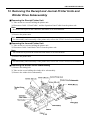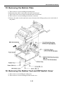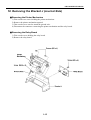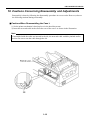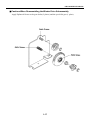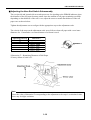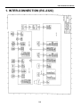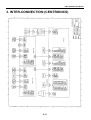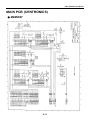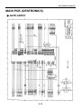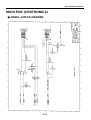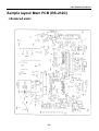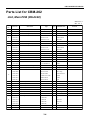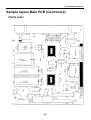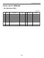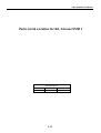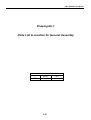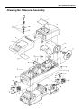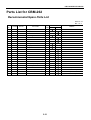
1
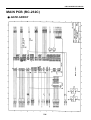
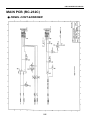
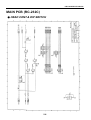
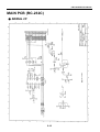
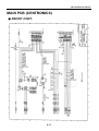
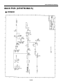
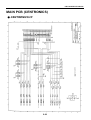
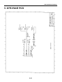
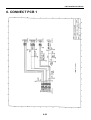
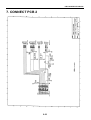
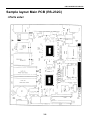
Service Manual
LINE THERMAL PRINTER
MODEL CBM-262
Rev.1.00 First created June.18th,1996
REVISION
Rev.No.
Rev. 1.00
Date
June.18,1996
Content
First created
i
CONTENTS
Chapter 1
Disassembly
Reassembly
Maintenance
Chapter 2
Circuit Diagrams
Chapter 3
Parts Lists
Chapter 4
Appendix
ii
CHAPTER 1
DISASSEMBLY
REASSEMBLY
MAINTENANCE
CHAPTER 1
Disassembly,Reassembly,Maintenance
Contents
1. Cautions Concerning Maintenance ........................................................................ 1-1
2. Supplying Oil ........................................................................................................... 1-2
3. Maintenance Tools ................................................................................................... 1-3
4. Other ......................................................................................................................... 1-3
5. Removing the Printer Covers ................................................................................. 1-4
■ Removing the Cover R .......................................................................................... 1-4
■ Removing the Cover J ........................................................................................... 1-4
6. Removing the Cover Window ................................................................................. 1-4
7. Removing the Journal Cover Key .......................................................................... 1-5
8. Removing the Spool and Writing Plate ................................................................. 1-6
■ Removing the Spool .............................................................................................. 1-6
■ Removing the Writing Plate ................................................................................... 1-6
9. Removing the Case L ............................................................................................... 1-7
10. Removing the Near End Switch Subassembly ...................................................... 1-8
11. Removing the Pressure Roller ................................................................................ 1-8
12. Removing the Paper Near End Sensor Subassembly ........................................... 1-9
13. Removing the Receipt and Journal Printer Units and
Winder Drive Subassembly .................................................................................. 1-10
■ Removing the Receipt Printer Unit ...................................................................... 1-10
■ Removing the Journal Printer Unit ...................................................................... 1-10
■ Removing the Winder Drive Subassembly .......................................................... 1-10
14. Removing the Spool Gear, Winder Pulley and Spool Idle Gear ........................ 1-11
15. Removing the Bottom Plate .................................................................................. 1-12
16. Removing the Rubber Feet and DIP Switch Cover ............................................ 1-12
17. Removing the Bracket R (Receipt Side) .............................................................. 1-13
■ Removing the Auto Cutter ................................................................................... 1-13
■ Removing the Auto Cutter Paper Guide .............................................................. 1-13
■ Removing the Relay Board .................................................................................. 1-13
■ Removing the Cutter Lock Lever ........................................................................ 1-13
■ Removing the Printer Mechanism ....................................................................... 1-14
■ Removing the Operation Panel Board and the Cover Open Switch Board ......... 1-14
18. Removing the Bracket J (Journal Side) ............................................................... 1-15
■ Removing the Printer Mechanism ....................................................................... 1-15
■ Removing the Relay Board .................................................................................. 1-15
19. Cautions Concerning Reassembly and Adjustments .......................................... 1-16
■ Cautions When Reassembling the Case L ........................................................... 1-16
■ Cautions When Reassembling the Winder Drive Subassembly .......................... 1-17
■ Adjusting the Near End Switch Subassembly ...................................................... 1-18
■ Adjusting the Timing Belt .................................................................................... 1-19
CBM-262 SERVICE MANUAL
1 Disassembly,Reassembly,Maintenance
1. Cautions Concerning Maintenance
Warning
(1) When disassembling, reassembling or adjusting the printer, disconnect the AC adapter from the
printer.
(2) When replacing a fuse, switch off the power switch first.
(3) A fuse is used for fire prevention. Be sure to use the same type when replacing the fuse.
Exercise caution regarding the following items when performing maintenance.
Caution
(1) Do not disassemble and reassemble, or make adjustments to the printer unnecessarily when
there is no abnormal or malfunctioning condition. In particular, do not loosen any of the
installation screws for any of the printer’s components unnecessarily.
(2) When finishing the maintenance, always check to make sure there is nothing abnormal before
switching on the power.
(3) By all means avoid printing without paper set in the printer.
(4) Make sure the printer has been set correctly.
(5) Do not place items on top of the cover or lean anything against it during maintenance or during
printer operetion.
(6) Be careful not to leave parts or screws, etc. used during maintenance lying around loose inside
the printer.
(7) When handling printed circuit boards, do not wear gloves which can easily generate a static
charge. The CPU, RAM, ROM and other IC’s can be destroyed by static electricity, so do not
touch the leads or window carelessly.
(8) Do not place the printed circuit boards directly on equipment or on the floor.
(9) During disassembly and reassembly, check wiring cords for damage, and do not exert undue
force on the wires during installation.
1-1
CBM-262 SERVICE MANUAL
2. Supplying Oil
(1) Oiling Intervals
This printer is maintenance free, and supplying of oil is unnecessary under conditions of normal
use. Supply oil when disassembling, reassembling, replacing parts or cleaning.
(2) Types of Oil
Froil Grease, Cat. No.G-311S, Kanto Kasei Kogyo (Co.,Ltd.)
Epiknock Grease, Cat. No.AP-1, Nihon Sekiyu (Co.,Ltd.)
(3) Oil Supply Quantities
Reper to the following table when supplying oil.
No.
1
2
3
Place Oiled
Spool Gear Shaft
Spool Idle Gear Shaft
Spool spring insert of
spool idle gear
Both ends of paper
holder roller
Circumference of the vibrator
unit.
Type of Oil
Epiknock Grease
Epiknock Grease
Froil Grease
1-2
Amount Supplied
0.2 mm width,
3 places.
0.2 mm width,
entire circumference.
0.2 mm width,
3 places.
CBM-262 SERVICE MANUAL
3. Maintenance Tools
The following maintenance tools are necessary when replacing components, etc. in the printer in
field service.
No.
1
2
3
4
5
6
7
8
9
10
Name
No.1(+)Screwdriver
(Shaft length: 200 mm)
No.2(+)Screwdriver
(Shaft length: 200 mm)
(–)Screwdriver
Tweezers
Tester
Needle Nose Pliers
(+)Screwdriver:
Precision Screwdriver
Dial Tension Gauge
Socket Wrench (Small)
Opposite side distance: 8 mm
Socket Wrench (Large)
Opposite side distance: 14 mm
Quantity
Use
1
For M3, M4 mm screws
1
For M2-M2.6 mm screws
Remarks
1
1
1
1
1
1
1
For M6
1
For M12
4. Other
For disassembly and reassembly of the printer unit (following), refer to the LT-283 Series Service
Manual.
1-3
CBM-262 SERVICE MANUAL
5. Removing the Printer Covers
■ Removing the Cover R
1) Open the Cover R.(→①)
2) Pull it out toward the front.(→➁)
■ Removing the Cover J
1) Open the Cover J.(→①)
2) Open it further toward the back and pull it out.(→➁)
6. Removing the Cover Window
Press on the center of the cover window,
then remove it while deflecting it.
1-4
CBM-262 SERVICE MANUAL
7. Removing the Journal Cover Key
If the optional cover key is set, remove the key by the following procedure.
1) Take out the hexagonal nut (M6).
2) Remove the key lever.
3) Take out the hexagonal nut (M12).
4) Remove the key plate.
5) Pull the key out toward the top.
1-5
CBM-262 SERVICE MANUAL
8. Removing the Spool and Writing Plate
■ Removing the Spool
1) Remove the spool by lifting it in the arrow ① direction.
2) Take the spool partner out in the arrow ➁ direction.
■ Removing the Writing Plate
1) Press the arrow mark ③ on the writing plate to release the lock.
2) Pull the writing plate out while pushing on the snap-in tabs in the arrow ④ direction.
1-6
CBM-262 SERVICE MANUAL
9. Removing the Case L
1) Take out the four screws holding the case L.
2) Set the printer’s paper release lever toward the rear.
3) Remove the case L.
Note
When removing the case L, be careful not to pull on or break any cables.
4) Loosen the ground wire screws (2 pcs).
5) Disconnect the connectors (2 pcs).
Note
Do not disconnect them by pulling on the wires.
1-7
CBM-262 SERVICE MANUAL
10. Removing the Near End Switch Subassembly
1) Using a coin, etc. loosen the screw holding the near end switch subassembly.
2) Remove the near end switch subassembly in the arrow direction.
Note
Near end switch subassemblies are located in two places, on the receipt side and on the journal
side.
11. Removing the Pressure Roller
Using a precision screwdriver or similar tool, push the pressure roller out from the rear.
1-8
CBM-262 SERVICE MANUAL
12. Removing the Paper Near End Sensor Subassembly
1) Remove the screw used to set the ground wire.
2) Remove the spring holding the near end switch lever.
3) Remove the near end switch lever.
4) Take out the two screws holding the paper near end sensor subassembly (microswitch).
1-9
CBM-262 SERVICE MANUAL
13. Removing the Receipt and Journal Printer Units and
Winder Drive Subassembly
■ Removing the Receipt Printer Unit
1) Take out the two screws holding the printer unit.
2) Disconnect Cable 1, Head Cable 1 and the Operation Panel Cable from the printer unit.
Note
Be careful not to pull on the connectors and cables so as to break them.
3) Remove the printer unit.
Note
For disassembly and reassembly of the printer unit, refer to the LT-283 Series Service Manual.
■ Removing the Journal Printer Unit
1) Take out the two screws holding the printer unit.
2) Disconnect Cable 2 and Head Cable 2 from the printer unit.
Note
Be careful not to pull on the connectors and cables so as to break them.
3) Remove the printer unit.
Note
For disassembly and reassembly of the printer unit, refer to the LT-283 Series Service Manual.
■ Removing the Winder Drive Subassembly
1) Remove the timing belt.
2) Take out the screw holding the winder drive subassembly.
3) Remove the winder drive subassembly.
1-10
CBM-262 SERVICE MANUAL
14. Removing the Spool Gear, Winder Pulley and
Spool Idle Gear
1) Remove the E-ring holding the spool gear.
2) Take off the spool gear.
3) Remove the E-ring holding the winder pulley.
4) Take off the winder pulley.
5) Take off the spool idle gear.
6) Take hold of the hook of the spool spring with a pair of tweezers, then turn the spool idle gear in
the arrow direction ① (the direction in which the spring becomes loose) and remove the spool
spring.
Note :Cautions in Reassembly
1) Assemble the spool spring with the hook toward the front.
2) Align the slit in the winder pulley with the hook of the spool spring to assemble.
1-11
CBM-262 SERVICE MANUAL
15. Removing the Bottom Plate
1) Take out the two screws holding the bottom plate.
2) Disconnect the cables connected to the main circuit board.
3) Take out the four screws used to mount the main circuit board.
4) Take out the two screws holding the interface connector.
5) Remove the main circuit board in the arrow direction while lifting up the power switch side of
the printer.
16. Removing the Rubber Feet and DIP Switch Cover
1) Take out the screws holding the rubber feet.
2) Take out the two screws holding the DIP switch cover.
1-12
CBM-262 SERVICE MANUAL
17. Removing the Bracket R (Receipt Side)
■ Removing the Auto Cutter
1) Take out the two screws holding the auto cutter.
2) Remove the auto cutter upward.
3) Disconnect the connector connecting the auto cutter and the relay board.
■ Removing the Auto Cutter Paper Guide
1) Take out the four screws holding the auto cutter paper guide.
2) Remove the auto cutter paper guide.
■ Removing the Relay Board
1) Take out the screw holding the relay board.
2) Remove the relay board.
■ Removing the Cutter Lock Lever
1) Take out the screw holding the cutter lock lever.
2) Remove the cutter lock lever.
1-13
CBM-262 SERVICE MANUAL
■ Removing the Printer Mechanism
1) Take out the two screws holding the printer mechanism.
2) Remove the printer mechanism upward.
3) Take out the screw used to attach the ground wire.
4) Disconnect the connector connecting the printer mechanism and the relay board.
■ Removing the Operation Panel Board and the Cover Open Switch Board
1) Take out the two screws holding the operation panel board.
2) Take out the screw holding the cover open switch board.
3) Remove the operation panel and cover open switch board.
1-14
CBM-262 SERVICE MANUAL
18. Removing the Bracket J (Journal Side)
■ Removing the Printer Mechanism
1) Take out the two screws holding the printer mechanism.
2) Remove the printer mechanism upward.
3) Take out the screw used to attach the ground wire.
4) Disconnect the connector connecting the printer mechanism and the relay board.
■ Removing the Relay Board
1) Take out the screw holding the relay board.
2) Remove the relay board.
1-15
CBM-262 SERVICE MANUAL
19. Cautions Concerning Reassembly and Adjustments
Reassembly is done by following the disassembly procedure in reverse order. However, observe
the following cautions during reassembly.
■ Cautions When Reassembling the Case L
1) Set the printer mechanism’s head up lever in the head down state.
2) Insert the near end cable in the slit on the rear of the case L as shown in the illustration.
Note
If assembled with the cable not inserted in the slit, the near end cable could be pinched and be
broken. Be sure to run the cable through the slit.
1-16
CBM-262 SERVICE MANUAL
■ Cautions When Reassembling the Winder Drive Subassembly
Apply Epiknock Grease to the gear shafts (2 places) and the spool idle gear (1 place).
1-17
CBM-262 SERVICE MANUAL
■ Adjusting the Near End Switch Subassembly
The receipt side and journal side near end sensors are for signaling to the ERROR indicator when
the diameter of the roll paper becomes small. since the amount of roll paper remaining can differ
depending on the thickness of the roll’s core, adjust the sensor to match the thickness of the roll
paper core as shown below.
Tighten the adjustment screw to align with the appropriate step on the adjustment scale.
The criteria of the steps on the adjustment scale are as follows when roll paper with a core inner
diameter of ø 12 mm and a core outer diameter of ø18 mm is used.
Adjustment Scale Step
#1
#2
#3
#4
#5
#6
Dimension T
Approx. 18mm
Approx. 20mm
Approx. 22mm
Approx. 24mm
Approx. 26mm
Approx. 28mm
*Dimension T = Remaining Diameter of Roll Paper
*Factory defaut of scale is #3.
Note
Since the value of dimension T corresponding to the adjustment scale steps is a calculated value,
there may be slight variations.
1-18
CBM-262 SERVICE MANUAL
■ Adjusting the Timing Belt
1) Loosen the screw holding the winder drive subassembly.
2) Adjust the belt tension to the specified value using a dial tension gauge.
Note
To adjust the belt tension, loosen the winder drive subassembly mounting screw and move the
winder drive subassembly backward or forward.
3) After adjustment to the specified value, tighten the screw securely, then check again that the
timing belt’s tension is at the specified value.
Specified Value: 15g ± 5g
(Belt deflection 2.5 mm)
1-19
CHAPTER 2
CIRCUIT DIAGRAMS
CHAPTER 2
Circuit Diagrams
Contents
1.INTER-CONNECTION (RS-232C) .......................................................................... 2-1
2.MAIN PCB (RS-232C) ............................................................................................... 2-2
■ CPU .......................................................................................................................... 2-2
■ MEMORY ................................................................................................................ 2-3
■ GATE ARRAY ......................................................................................................... 2-4
■ PANEL CONT.& DRWER ...................................................................................... 2-5
■ HEAD CONT.& DIP SWITCH ............................................................................... 2-6
■ RECEIPT CONT. ..................................................................................................... 2-7
■ JOURNAL CONT. ................................................................................................... 2-8
■ POWER .................................................................................................................... 2-9
■ SERIAL I/F ............................................................................................................ 2-10
3.INTER-CONNECTION (CENTRONICS) ............................................................ 2-11
4.MAIN PCB (CENTRONICS) .................................................................................. 2-12
■ CPU ........................................................................................................................ 2-12
■ MEMORY .............................................................................................................. 2-13
■ GATE ARRAY ....................................................................................................... 2-14
■ PANEL CONT.& DRWER .................................................................................... 2-15
■ HEAD CONT.& DIP SWITCH ............................................................................. 2-16
■ RECEIPT CONT. . ................................................................................................. 2-17
■ JOURNAL CONT. ................................................................................................. 2-18
■ POWER .................................................................................................................. 2-19
■ CENTRONICS I/F ................................................................................................. 2-20
5.OPE-PANE PCB ....................................................................................................... 2-21
6.CONNECT PCB 1 .................................................................................................... 2-22
7.CONNECT PCB 2 .................................................................................................... 2-23
CBM-262 SERVICE MANUAL
1. INTER-CONNECTION (RC-232C)
2-1
CBM-262 SERVICE MANUAL
2. MAIN PCB (RC-232C)
● CPU
2-2
CBM-262 SERVICE MANUAL
MAIN PCB (RC-232C)
● MEMORY
2-3
CBM-262 SERVICE MANUAL
MAIN PCB (RC-232C)
● GATE ARRAY
2-4
CBM-262 SERVICE MANUAL
MAIN PCB (RC-232C)
● PANEL CONT.&DRAWER
2-5
CBM-262 SERVICE MANUAL
MAIN PCB (RC-232C)
● HEAD CONT.& DIP SWITCH
2-6
CBM-262 SERVICE MANUAL
MAIN PCB (RC-232C)
● RECEIPT CONT.
2-7
CBM-262 SERVICE MANUAL
MAIN PCB (RC-232C)
● JOURNAL CONT.
2-8
CBM-262 SERVICE MANUAL
MAIN PCB (RC-232C)
● POWER
2-9
CBM-262 SERVICE MANUAL
MAIN PCB (RC-232C)
● SERIAL I/F
2-10
CBM-262 SERVICE MANUAL
3. INTER-CONNECTION (CENTRONICS)
2-11
CBM-262 SERVICE MANUAL
4. MAIN PCB (CENTRONICS)
● CPU
2-12
CBM-262 SERVICE MANUAL
MAIN PCB (CENTRONICS)
● MEMORY
2-13
CBM-262 SERVICE MANUAL
MAIN PCB (CENTRONICS)
● GATE ARRAY
2-14
CBM-262 SERVICE MANUAL
MAIN PCB (CENTRONICS)
● PANEL CONT.& DRAWER
2-15
CBM-262 SERVICE MANUAL
MAIN PCB (CENTRONICS)
● HEAD CONT.& DIP SWITCH
2-16
CBM-262 SERVICE MANUAL
MAIN PCB (CENTRONICS)
● RECEIT CONT.
2-17
CBM-262 SERVICE MANUAL
MAIN PCB (CENTRONICS)
● JOURNAL CONT.
2-18
CBM-262 SERVICE MANUAL
MAIN PCB (CENTRONICS)
● POWER
2-19
CBM-262 SERVICE MANUAL
MAIN PCB (CENTRONICS)
● CENTRONICS I/F
2-20
CBM-262 SERVICE MANUAL
5. OPE-PANE PCB
2-21
CBM-262 SERVICE MANUAL
6. CONNECT PCB 1
2-22
CBM-262 SERVICE MANUAL
7. CONNECT PCB 2
2-23
CHAPTER 3
PARTS LISTS
CHAPTER 3
Parts Lists
Contents
Electrical Parts .................................................................................................. 3-1
Unit, Main PCB (RS-232C) ........................................................................................ 3-1
Unit, Main PCB (Centronics) ...................................................................................... 3-7
SA, Ope-Pane PCB 1 ................................................................................................. 3-12
SA, Connect PCB 1 ................................................................................................... 3-15
SA, Connect PCB 2 ................................................................................................... 3-18
Mechanical Parts ............................................................................................ 3-21
1. General Assembly .................................................................................................. 3-21
2. Mechanism Unit .................................................................................................... 3-24
3. Electrical Component Unit .................................................................................... 3-27
Recommended Spare Parts List .................................................................... 3-30
CBM-262 SERVICE MANUAL
Parts List & Location for Unit, Main PCB (RS-232C)
Revision Up List
Sheet No.
1/3
2/3
3/3
Rev.No.
1
1
1
3-1
Date
Jun.18.1996
Jun.18.1996
Jun.18.1996
CBM-262 SERVICE MANUAL
Sample layout Main PCB (RS-232C)
<Parts side>
3-2
CBM-262 SERVICE MANUAL
Sample layout Main PCB (RS-232C)
<Soldered side>
3-3
CBM-262 SERVICE MANUAL
Parts List for CBM-262
Unit, Main PCB (RS-232C)
Sheet No. 1/3
Rev. No. 1
Item
No.
Part Name
Part No.
Type
Q'ty
1
PC66804-0
Unit, Main PCB(with ROM)
<for Japan>
1
2
PC66806-0
Unit, Main PCB(with ROM)
<for USA/Europe>
1
3
PC94702-0
ROM-Set 3(Prog.+C.G.)
C2304-615
EP-ROM(Brank)
4
(C2304-615)
(C2304-615)
AM27C512-150
1
Label, ROM
6
PC94703-0
ROM-Set 4(Prog.+C.G.)
C2304-615
EP-ROM(Brank)
K5688-411
AMD
Central
1
M27C512-15
SGS-Tomson
(C2304-615)
MX27C512-15
Macronix
AF99916-00
Label, ROM
K5688-411
1
9
PC66704-0
SA, Main PCB(without ROM)
<for Japan>
1
10
PC66706-0
SA, Main PCB(without ROM)
<for USA/Europe>
1
11
C2900-052
IC(Reset)
PST591DMT
12
C2400-009
CPU
M37720S1AFP
C2323-610
RAM(Pseudo Static)
LC33864M-10
(IC4)
IC5
AMD
(C2304-615)
(C2323-610)
(IC4)
Macronix
1
8
13
IC4
1
AM27C512-150
Location
SGS-Tomson
MX27C512-15
AF99916-00
7
1
M27C512-15
5
Manufacturer
(IC5)
Central
(IC5)
1
Mitsumi
IC1
1
2
Mitsubishi
IC2
Sanyo
IC3, 16
Sanyo
LC33864ML-10
14
PC95900-0
Mask ROM(C.G)<for Japan>
LH5348R7
1
Sharp
IC6
15
PC95900-0
Mask ROM(C.G)<for USA/Europe> LH5348R7
0
Sharp
IC6
C2320-009
EEP-ROM
1
Sanyo
IC7
16
LE24C01MI-TE-L
(C2320-008)
24C01A-/SN
Microchip
(C2320-010)
ST24C01M1
SGS-Thomson
(C2320-015)
AT24C01A-10SC
Atmel
(C2320-016)
BR24C01AF
Rohm
(C2320-017)
Exel
XL24C01AF
17
C2527-402
Gate Array
M6513FP
1
Mitsubishi
IC8
18
C2216-373
IC(CMOS)
HD74HC373FP
1
Hitachi
IC9
19
C2262-032
IC(CMOS)
HD74AC32FP
1
Hitachi
IC10
20
C2216-000
IC(CMOS)
HD74HC00FP
1
Hitachi
IC11
21
C2900-057
IC(I/F)
µPD4721
1
NEC
IC12
22
C2709-001
IC(Drive)
MTD2003F
2
Shindengen
IC13,14
23
C2703-428
IC(Drive)
TA8428K
1
Toshiba
IC15
C2603-393
IC(Comparator)
BA10393F
1
Rohm
IC19
24
(C2603-393)
LM393PS
T.I.
(C2603-393)
LM393D
Motorola
(C2603-393)
LM393M
Motorola
(C2603-393)
LM393M
N.S.
25
C3402-143
Transistor
2SD2143
2
Rohm
TR1,2
26
C3903-046
Transistor
2SJ302-Z
1
NEC
TR4
3-4
CBM-262 SERVICE MANUAL
Parts List for CBM-262
Unit, Main PCB (RS-232C)
Sheet No. 2/3
Rev. No. 1
Item
No.
Type
Part Name
Part No.
Q'ty
Location
Manufacturer
1
C3905-015
Transistor(Res.)
FMA4A
1
Rohm
DTRA1
2
C3905-006
Transistor(Res.)
DTA114WK
2
Rohm
DTR1,4
3
C3905-014
Transistor(Res.)
DTC114WK
1
Rohm
DTR2
C3621-001
Diode(Silicon)
MA151WK
1
Matsushita
D1
4
(C3621-002)
MA152WK
Matsushita
(C3621-000)
DAN202K
Rohm
(C3621-003)
DCB010
Sanyo
5
C3629-000
Diode(Silicon)
MA153
1
Matsushita
D5
6
C3610-044
Diode(Silicon)
RB420D
1
Rohm
D6
7
C7425-166
Oscillator(Ceramic)
EFOEC1605C4
1
Matsushita
Y1
8
C6180-093
Connector
TCS7960-53-2010
1
Hoshiden
CN1
9
C6149-142
Connector
17LE-13250-27(D41)
1
DDK
CN2
10
C6149-143
Connector
285D-7660J-101
1
DDK
CN3
11
C6198-713
Connector
13FE-BT-VK-N
2
JST
CN4,6
12
C6196-716
Connector
B16B-PH-K-S
2
JST
CN5,7
13
C6196-706
Connector
B6B-PH-K-S
1
JST
CN8
14
C7100-128
IC Socket
DILB28P-8J
2
Burndy
IC4,5
15
C7219-020
Switch(Dip)
SSGM18
1
Alps
SW1
16
C7219-021
Switch(Dip)
SSGM14
1
Alps
SW2
17
C7602-104
Switch(Power)
SF-W1P1A-14BB
1
Echo Elec.
SW3
18
C5270-053
Cap.Chip
B,±10%,50V,0.01µF
30
19
C5270-051
Cap.Chip
CH,±5%,50V,1000pF
2
C15,32
20
C5270-044
Cap.Chip
CH,±5%,50V,30pF
7
C17~23
21
C5270-170
Cap.Chip
F,±5%,50V,0.1µF
1
C59
22
C5190-474
Cap.Electrolytic
35WA1000Mφ16×L16
1
Rubycon
EC1
23
C5190-475
Cap.Electrolytic
6.3REV100Mφ6.3×L5.5
1
Rubycon
EC2
24
C5190-476
Cap.Electrolytic
16REV22Mφ5×L5.5
5
Rubycon
EC4~8
25
C2800-046
IC(Regulator)
SI-8401L
1
Sanken
REG1
26
C7302-365
Microton Fuse
TR/3216FF⋅1.5A
2
Bussmann
F1,3
27
C7510-090
Coil
PLT1R53C
1
Murata
L1
28
C4932-035
Res.Chip
1/10W,±1%,10KΩ
2
R1,57
29
C4932-052
Res.Chip
1/10W,±5%,2KΩ
1
R2
30
C4922-332
Res.Chip
1/10W,±5%,3.3KΩ
31
31
C4922-105
Res.Chip
1/10W,±5%,1MΩ
1
R4
32
C4922-101
Res.Chip
1/10W,±5%,100Ω
1
R5
33
C4922-102
Res.Chip
1/10W,±5%,1KΩ
1
R12
34
C4922-271
Res.Chip
1/10W,±5%,270Ω
2
R14,29
C1~14,16,24~28,33,40,44
51,53,57,58,63,64,73
R3,6,8~11,15~17,19~25
27,28,30,32,34~38,40~43
46,54
3-5
CBM-262 SERVICE MANUAL
Parts List for CBM-262
Unit, Main PCB (RS-232C)
Sheet No. 3/3
Rev. No. 1
Item
No.
Part No.
Part Name
Type
Q'ty
Manufacturer
Location
1
C4922-753
Res.Chip
1/10W,±5%,75KΩ
2
R18,33
2
C4932-063
Res.Chip
1/10W,±1%,30KΩ
2
R26,39
3
C4922-512
Res.Chip
1/10W,±5%,5.1KΩ
1
R48
4
C4922-103
Res.Chip
1/10W,±5%,10KΩ
3
R49,59,61
5
C4932-016
Res.Chip
1/10W,±1%,3.3KΩ
1
R58
6
C4922-104
Res.Chip
1/10W,±5%,100KΩ
1
R60
7
C4922-000
Res.Chip
1/10W,0Ω(Jumper)
19
C52,FB1~14,JP1,2,5,6
8
C4920-000
Res.Chip
1/8W,0Ω(Jumper)
1
F2
9
C4494-002
Res.Array(Chip)
EXBS8V332J
7
3-6
Matsushita
RN1~7
CBM-262 SERVICE MANUAL
Parts List & Location for Unit, Main PCB (Centronics)
Revision Up List
Sheet No.
1/2
2/2
Rev.No.
1
1
3-7
Date
Jun.18.1996
Jun.18.1996
CBM-262 SERVICE MANUAL
Sample layout Main PCB (Centronics)
<Parts side>
3-8
CBM-262 SERVICE MANUAL
Sample layout Main PCB (Centronics)
<Soldered side>
3-9
CBM-262 SERVICE MANUAL
Parts List for CBM-262
Unit, Main PCB (Centronics)
Sheet No. 1/2
Rev. No. 1
Item
No.
Part Name
Part No.
Type
Q'ty
1
PC66805-0
Unit, Main PCB(with ROM)
<for Japan>
1
2
PC66807-0
Unit, Main PCB(with ROM)
<for USA/Europe>
1
3
PC94702-0
ROM-Set 3(Prog.+C.G.)
C2304-615
EP-ROM(Brank)
4
1
AMD
(C2304-615)
M27C512-15
SGS-Tomson
(C2304-615)
MX27C512-15
Macronix
5
AF99916-00
Label, ROM
6
PC94703-0
ROM-Set 4(Prog.+C.G.)
C2304-615
EP-ROM(Brank)
7
IC4
1
AM27C512-150
(C2304-615)
K5688-411
1
1
(IC4)
(IC4)
IC5
AMD
(IC5)
SGS-Tomson
M27C512-15
(C2304-615)
Central
1
AM27C512-150
Location
Manufacturer
Macronix
MX27C512-15
8
AF99916-00
Label, ROM
K5688-411
1
Central
(IC5)
9
PC66705-0
SA, Main PCB(without ROM)
<for Japan>
1
10
PC66707-0
SA, Main PCB(without ROM)
<for USA/Europe>
1
11
C2900-052
IC(Reset)
PST591DMT
1
Mitsumi
IC1
12
C2400-009
CPU
M37720S1AFP
1
Mitsubishi
IC2
C2323-610
RAM(Pseudo Static)
LC33864M-10
2
Sanyo
IC3, 16
13
(C2323-610)
Sanyo
LC33864ML-10
14
PC95900-0
Mask ROM(C.G)<for Japan>
LH5348R7
1
Sharp
IC6
15
PC95900-0
Mask ROM(C.G)<for USA/Europe> LH5348R7
0
Sharp
IC6
C2320-009
EEP-ROM
1
Sanyo
IC7
16
LE24C01M1-TE-L
(C2320-008)
24C01A-/SN
Microchip
(C2320-010)
ST24C01M1
SGS-Tomson
(C2320-015)
AT24C01A-10SC
Atmel
(C2320-016)
BR24C01AF
Rohm
(C2320-017)
XL24C01AF
Exel
17
C2527-402
Gate Array
M65135FP
1
Mitsubishi
IC8
18
C2216-373
IC(CMOS)
HD74HC373FP
1
Hitachi
IC9
19
C2262-032
IC(CMOS)
HD74AC32FP
1
Hitachi
IC10
20
C2216-000
IC(CMOS)
HD74HC00FP
1
Hitachi
IC11
21
C2108-006
IC(TTL)
HD74LS06FP
1
Hitachi
IC12
22
C2709-001
IC(Drive)
MTD2003F
2
Shindengen
IC13,14
23
C2703-428
IC(Drive)
TA8428K
1
Toshiba
IC15
24
C3402-143
Transistor
2SD2143
2
Rohm
TR1,2
25
C3903-046
Transistor
2SJ302-Z
1
NEC
TR4
26
C3905-015
Transistor(Res.)
FMA4A
1
Rohm
DTRA1
27
C3905-006
Transistor(Res.)
DTA114WK
2
Rohm
DTR1,4
28
C3905-014
Transistor(Res.)
DTA114WK
1
Rohm
DTR2
29
C7425-166
Oscillator(Ceramic)
EFOEC1605C4
1
Matsushita
Y1
3-10
CBM-262 SERVICE MANUAL
Parts List for CBM-262
Unit, Main PCB (Centronics)
Sheet No. 2/2
Rev. No. 1
Item
No.
C3621-001
1
Part Name
Part No.
Diode(Silicon)
Type
MA151WK
Q'ty
1
Manufacturer
Matsushita
(C3621-002)
MA152WK
Matsushita
(C3621-000)
DAN202K
Rohm
(C3621-003)
Location
D1
Sanyo
DCB010
2
C6180-093
Connector
TCS7960-53-2010
1
Hoshiden
CN1
3
C6149-145
Connector
57RE-40360-830B(D29)
1
DDK
CN2
4
C6149-143
Connector
285D-7660J-101
1
DDK
CN3
5
C6198-713
Connector
13FE-BT-VK-N
2
JST
CN4,6
6
C6196-716
Connector
B16B-PH-K-S
2
JST
CN5,7
7
C6196-706
Connector
B6B-PH-K-S
1
JST
CN8
8
C7100-128
IC Socket
DILB28P-8J
2
Burndy
IC4,5
9
C7219-020
Switch(Dip)
SSGM18
1
Alps
SW1
10
C7602-104
Switch(Power)
SF-W1P1A-14BB
1
Echo Elec.
SW3
11
C5270-053
Cap.Chip
B,±0%,50V,0.01µF
30
12
C5270-051
Cap.Chip
CH,±5%,50V,1000pF
3
C15,32,63
13
C5270-044
Cap.Chip
CH,±5%,50V,30pF
7
C17~23
14
C5270-170
Cap.Chip
F,±5%,50V,0.1µF
1
C59
15
C5270-121
Cap.Chip
CH,±5%,50V,100pF
6
C65~70
16
C5190-474
Cap.Electrolytic
35WA1000Mφ16×L16
1
Rubycon
EC1
17
C5190-475
Cap.Electrolytic
6.3REV100Mφ6.3×L5.5
1
Rubycon
EC2
18
C2800-046
IC(Regulator)
SI-8401L
1
Sanken
REG1
19
C7302-365
Microton Fuse
TR/3216FF⋅1.5A
2
Bussmann
F1,3
20
C7510-090
Coil
PLT1R53C
1
Murata
L1
21
C4932-035
Res.Chip
1/10W,±1%,10KΩ
1
R1
22
C4932-052
Res.Chip
1/10W,±1%,2KΩ
1
R2
23
C4922-105
Res.Chip
1/10W,±5%,1MΩ
1
R4
24
C4922-332
Res.Chip
1/10W,±5%,3.3KΩ
33
25
C4922-101
Res.Chip
1/10W,±5%,100Ω
2
R5,47
26
C4922-102
Res.Chip
1/10W,±5%,1KΩ
1
R12
27
C4922-271
Res.Chip
1/10W,±5%,270Ω
2
R14,29
28
C4922-753
Res.Chip
1/10W,±5%,75KΩ
2
R18,33
29
C4932-063
Res.Chip
1/10W,±1%,30KΩ
2
R26,39
30
C4922-000
Res.Chip
1/10W,0Ω(Jumper)
17
C52,FB1~14,JP1,2
31
C4920-000
Res.Chip
1/8W,0Ω(Jumper)
2
32
C4494-002
Res.Array(Chip)
EXBS8V332J
13
C1~14,16,24~28,33,40,44
51,53,57,58,64,71,73
R3,7~11,15~17,19~25,27
28,30,32,34~38,40~43,46
48,49,54
3-11
F2,4
Matsushita
RN1~13
CBM-262 SERVICE MANUAL
Parts List & Location for SA, Ope-Pane PCB 1
Revision Up List
Sheet No.
1/1
Rev.No.
1
3-12
Date
Jun.18.1996
CBM-262 SERVICE MANUAL
Sample layout Ope-Pane PCB
<Parts side>
<Soldered side>
3-13
CBM-262 SERVICE MANUAL
Parts List for CBM-262
SA, Ope-Pane PCB 1
Sheet No. 1/1
Rev. No. 1
Item
No.
Part Name
Part No.
Type
Q'ty
Manufacturer
Location
1
PC66730-0
SA,Ope-Pane PCB 1
2
C3803-054
LED
SEL6510G
1
Sanken
LED1
3
C3803-056
LED
SEL6810D
1
Sanken
LED2
4
C7640-023
Switch(Key)
EVQ-233-04M
2
Matsushita
SW4,5
5
C7642-006
Switch(Detector)
SW-114S
1
Shinmei
SW6
6
C5270-053
Cap.Chip
B,±10%,50V,0.01µF
3
Murata
C101~103
7
C4922-181
Cap.Chip
1/10W,±5%,180Ω
1
Matsushita
R101
8
C4922-271
Cap.Chip
1/10W,±5%,270Ω
1
Matsushita
R102
1
Sumitomo
PT1-2
1
JST
CN9
1
SMV2RJ-B-7/0.16
9
PC67950-0
Cable,Cover Sensor 1
(OM-1S)×2×60 P2.0
53-M UL-2651
10
C6198-506
Connector
S6B-PH-K-S
3-14
CBM-262 SERVICE MANUAL
Parts List & Location for SA, Connect PCB 1
Revision Up List
Sheet No.
1/1
Rev.No.
1
3-15
Date
Jun.18.1996
CBM-262 SERVICE MANUAL
Sample layout Connect PCB 1
<Parts side>
<Soldered side>
3-16
CBM-262 SERVICE MANUAL
Parts List for CBM-262
SA, Connect PCB 1
Sheet No. 1/1
Rev. No. 1
Item
No.
Part Name
Part No.
Type
Q'ty
Manufacturer
Location
1
PC66790-0
SA,Connect PCB 1
2
C6198-713
Connector
13FE-BT-VK-N
1
JST
CN10
3
C6196-804
Connector
53047-0410
1
Molex
CN11
4
C6196-806
Connector
53047-0610
1
Molex
CN12
5
C6198-404
Connector
5267-04AX
1
Molex
CN13
6
C6198-502
Connector
S2B-PH-K-S
1
JST
CN14
7
C5270-053
Cap.Chip
B,±10%,50V,0.01µF
6
Murata
C201~205,207
8
C4922-181
Res.Chip
1/10W,±5%,180Ω
1
Matsushita
R201
9
C4922-000
Res.Chip
1/10W,0Ω(Jumper)
2
Matsushita
R202,JP201
1
3-17
CBM-262 SERVICE MANUAL
Parts List & Location for SA, Connect PCB 2
Revision Up List
Sheet No.
1/1
Rev.No.
1
3-18
Date
Jun.18.1996
CBM-262 SERVICE MANUAL
Sample layout Connect PCB 2
<Parts side>
<Soldered side>
3-19
CBM-262 SERVICE MANUAL
Parts List for CBM-262
SA, Connect PCB 2
Sheet No. 1/1
Rev. No. 1
Item
No.
Part Name
Part No.
Type
Q'ty
Manufacturer
Location
1
PC66791-0
SA,Connect PCB 2
2
C6198-713
Connector
13FE-BT-VK-N
1
JST
CN15
3
C6196-804
Connector
53047-0410
1
Molex
CN16
4
C6196-806
Connector
53047-0610
1
Molex
CN17
5
C6198-502
Connector
S2B-PH-K-S
1
JST
CN19
6
C5270-053
Cap.Chip
B,±10%,50V,0.01µF
6
Murata
C301~304,306,307
7
C4922-181
Res.Chip
1/10W,±5%,180Ω
1
Matsushita
R301
8
C4922-000
Res.Chip
1/10W,0Ω(Jumper)
3
Matsushita
R308,R302,JP301
1
3-20
CBM-262 SERVICE MANUAL
Drawing No.1
Parts List & Location for General Assembly
Revision Up List
Sheet No.
1/1
Rev.No.
1
3-21
Date
Jun.18.1996
CBM-262 SERVICE MANUAL
Drawing No.1 General Assembly
3-22
CBM-262 SERVICE MANUAL
Parts List for CBM-262
General Assembly
Drawing No.1
Sheet No. 1/1
Rev. No. 1
Location
Part No.
Part Name
Remark
Q'ty/Unit
1-1
PC56204-0
Cover,Window
1
-2
PC56203-0
Cover J
1
-3
PB56202-0
Cover R
1
-4
PC54104-0
Plate,Magnet
1
-5
T5429-02
Spool Partner
1
-6
PC29901-0
O Ring,P8
1
-7
PC24202-0
Spool
1
-8
PC56205-0
Plate,Writing
1
-9
PC56201-0
Case L
1
-10
T6816-01
Lever End Switch
2
-11
PC23602-0
Spring,Coil,NE
2
-12
PC24102-0
Holder,Switch,NE
2
-13
PC68700-0
SA,Paper Near End Sensor 1
2
-14
E00120-08
Screw,PH,M2×8
4
-15
E00130-04
Screw,PH,M3×4
2
-16
PC67790-0
SA,Earth Wire 1
2
-17
E11130-06
Screw,PHT(ST),M3×6
4
-18
PC22003-0
Screw,Switch,NE
2
-19
T6115-01
Roll Pressure
4
-20
PC54108-0
Sheet,Ope-Pane
1
-21
PC99906-0
Label,Paper Set,R
1
-22
PC99907-0
Label,Paper Set,J
1
-23
PC59902-0
Key,Cover
1 set
Factory Option
-24
PC54107-0
Plate,Key
1
Factory Option
-25
PC54106-0
Lever,Key
1
Factory Option
3-23
CBM-262 SERVICE MANUAL
Drawing No.2
Parts List & Location for Mechanism Unit
Revision Up List
Sheet No.
1/1
Rev.No.
1
3-24
Date
Jun.18.1996
CBM-262 SERVICE MANUAL
Drawing No.2 Mechanism Unit
3-25
CBM-262 SERVICE MANUAL
Parts List for CBM-262
Mechanism Unit
Drawing No.2
Sheet No. 1/1
Rev. No. 1
Location
Part Name
Part No.
2-1
PB99802-0
Unit,Printer(LT-283 for Journal)
1
-2
PC26901-0
Belt,Timing,Winder
1
-3
E00130-04
Screw,PH,M3×4
4
-4
PC66791-0
SA,Connect PCB 2
1
-5
E11130-06
Screw,PHT(ST),M3×6
14
-6
PC67793-0
SA,Connect Cable 2
1
-7
PC44103-0
Bracket J
1
-8
E11126-05
Screw,PHT(ST),M2.6×5
3
-9
PC67791-0
SA,Earth Wire 2
2
-10
PC67741-0
SA,Head Cable 2
1
-11
PC24702-0
SA,Winder Plate
1
-12
PC20201-0
Gear,Spool
1
-13
E60330-00
E-Ring,3
2
-14
PC20202-0
Gear,Spool Idle
1
-15
PC23601-0
Spring,Spool
1
-16
NE20205-1
Pulley,Winder
1
-17
PC44101-0
Plate,Main
1
-18
PC59901-0
Leg
2
-19
E11130-08
Screw,PHT(ST),M3×8
2
-20
PC29801-0
Auto Cutter(ACS-120)
1
-21
PC24201-0
Guide,Paper,Auto Cutter
1
-22
E11120-04
Screw,PHT(ST),M2×4
4
-23
PC44901-0
Lever,Lock,Cutter(60-0166)
1
-24
PC44102-0
Bracket R
1
-25
PC66790-0
SA,Connect PCB 1
1
-26
PC67792-0
SA,Connect Cable 1
1
-27
PC67730-0
SA,Ope-Pane Cable 1
1
-28
PC66730-0
SA,Ope-Pane PCB 1
1
-29
PB99801-0
Unit,Printer(LT-283 for Receipt)
1
-30
E00123-05
Screw,PH,M2.3×5
2
-31
PC67740-0
SA,Head Cable 1
1
-32
PC69920-0
Unit,AC Adapter(Jap)
1
C6005-100
Cord Set(Jap.) Black
1
(C6006-100)
Cord Set(Jap.) Black
-33
Remark
Q'ty/Unit
3-26
PB12-CBWXX
for RS-232C I/F
PB12-CBXXX
CBM-262 SERVICE MANUAL
Drawing No.3
Parts List & Location for Electrical Component Unit
Revision Up List
Sheet No.
1/1
Rev.No.
1
3-27
Date
Jun.18.1996
CBM-262 SERVICE MANUAL
Drawing No.3 Electrical Component Unit
<RS-232C I/F>
<Centronics I/F>
3-28
CBM-262 SERVICE MANUAL
Parts List for CBM-262
Electrical Component Unit
Drawing No.3
Sheet No. 1/1
Rev. No. 1
Location
Part No.
Q'ty/Unit
Part Name
Remark
3-1
E11630-06
Screw,TP(ST),M3×6
4
-2
PC69900-0
Screw,I/F(mm)
2
for RS-232C I/F
-3
PC66804-0
Unit,Main PCB(with ROM)
1
for RS-232C I/F,Japan
-3
PC66806-0
Unit,Main PCB(with ROM)
1
for RS-232C I/F,USA/Europe
-4
E11130-06
Screw,PHT(ST),M3×6
2
-5
PC54101-0
Plate,Bottom,Serial
1
-6
PC54103-0
Cover,DIP Switch
1
-7
E00130-04
Screw,PH,M3×4
2
for RS-232C I/F
-7
E00130-04
Screw,PH,M3×4
4
for Centronics I/F
-8
PC59901-0
Leg
2
-9
E11130-08
Screw,PHT(ST),M3×8
2
-10
PC66805-0
Unit,Main PCB(with ROM)
1
for Centronics I/F,Japan
-10
PC66807-0
Unit,Main PCB(with ROM)
1
for Centronics I/F,USA/Europe
-11
PC54102-0
Plate,Bottom,Parallel
1
for Centronics I/F
3-29
for RS-232C I/F
CBM-262 SERVICE MANUAL
Recommeded Spare Parts List
Revision Up List
Sheet No.
1/1
Rev.No.
1
3-30
Date
Jun.18.1996
CBM-262 SERVICE MANUAL
Parts List for CBM-262
Recommended Spare Parts List
Sheet No. 1/1
Rev. No. 1
Item
No.
Location
Q'ty/
Part Name
Part No.
Unit
Maint.Class
Worn
Casual
Remark
1
1-6
PC29901-0
O Ring,P8
1
2
1-13
PC68700-0
SA,Paper Near End Sensor 1
2
3
2-1
PB99802-0
Unit,Printer(LT-283 for Journal)
1
4
2-2
PC26901-0
Belt,Timing,Winder
1
5
2-4
PC66791-0
SA,Connect PCB 2
1
6
2-6
PC67793-0
SA,Connect Cable 2
1
7
2-10
PC67741-0
SA,Head Cable 2
1
8
2-14
PC20202-0
Gear,Spool Idle
1
9
2-15
PC23601-0
Spring,Spool
1
10
2-16
NE20205-1
Pulley,Winder
1
11
2-20
PC29801-0
Auto Cutter(ACS-120)
1
12
2-25
PC66790-0
SA,Connect PCB 1
1
13
2-26
PC67792-0
SA,Connect Cable 1
1
14
2-27
PC67730-0
SA,Ope-Pane Cable 1
1
15
2-28
PC66730-0
SA,Ope-Pane PCB 1
1
16
2-29
PB99801-0
Unit,Printer(LT-283 for Receipt)
1
17
2-31
PC67740-0
SA,Head Cable 1
1
18
2-32
PC69920-0
Unit,AC Adapter(Jap)
1
19
2-33
C6005-100
Cord Set(Jap.)Black
1
20
3-3
PC66804-0
Unit,Main PCB(with ROM)
1
for RS-232C I/F,Japan
21
3-3
PC66806-0
Unit,Main PCB(with ROM)
1
for RS-232C I/F,USA/Europe
22
3-10
PC66805-0
Unit,Main PCB(with ROM)
1
for Centro I/F,Japan
23
3-10
PC66807-0
Unit,Main PCB(with ROM)
1
for Centro I/F,USA/Europe
3-31
PB12-CBWXX
PB12-CBXXX
CHAPTER 4
APPENDIX
CHAPTER 4
Appendix
Contents
External View .................................................................................................... 4-1
CBM-262 SERVICE MANUAL
EXTERNAL VIEW
4-1