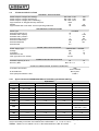
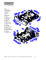
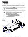
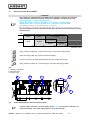
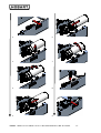
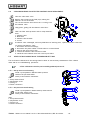
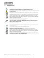
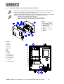
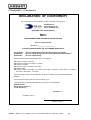
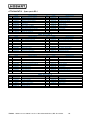
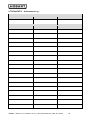
1
RO-I SERVICE MANUAL SERIAL NO.: PART NUMBER: __________________ INDEX 1. GENERAL INFORMATIONS ............................................................................................................... 4 1.1. MANUFACTURER / ASSISTANCE ......................................................................................................... 4 1.2. CERTIFICATION ............................................................................................................................. 4 1.3. PURPOSE OF THE MANUAL AND ITS CONTENTS .................................................................................... 4 1.4 CARE AND STORAGE OF THE MANUAL ................................................................................................ 4 1.5. IMPORTANT SYMBOLS TO REMEMBER ................................................................................................. 4 2. CHARACTERISTICS OF THE DEVICE................................................................................................. 5 2.1. RECOMMENDED USE........................................................................................................................ 5 2.2. SCHEMATIC REPRESENTATION .......................................................................................................... 5 2.3 DESCRIPTION ................................................................................................................................ 6 2.4 TECHNICAL SPECIFICATIONS............................................................................................................. 7 2.5 GENERAL DIMENSIONS “GC” HOUSING................................................................................................ 9 2.6 GENERAL DIMENSIONS “GX” HOUSING................................................................................................ 9 2.7 GENERAL DIMENSIONS “VERTICAL” HOUSING....................................................................................... 9 2.8 INTERNAL LAYOUT ........................................................................................................................10 3. INSTALLATION...............................................................................................................................11 3.1 DRAIN CAPILLARY REPLACEMENT .....................................................................................................12 3.2 INLET WATER SAFETY DEVICE INSTALLATION ......................................................................................12 3.3 DRAIN WATER SAFETY ADAPTER INSTALLATION...................................................................................13 3.4 “GC” AND “GX” HOUSING INSTALLATION...........................................................................................13 3.5 “VERTICAL” HOUSING ASSEMBLY .....................................................................................................14 3.6 POWER PLUG CONNECTION / REPLACEMENT......................................................................................14 4. FUNCTIONING................................................................................................................................15 4.1 FIRST START-UP ...........................................................................................................................15 4.2 NORMAL USE................................................................................................................................15 4.3 LOW PRESSURE ALARM...................................................................................................................15 4.4 LEACKAGE ALARM .........................................................................................................................15 4.5 STATUS LED.................................................................................................................................15 5. 5.1 6. ENDUSER ORDINARY MAINTEN ANCE ..............................................................................................16 FILTER REPLACEMENT....................................................................................................................16 PROFESSIONAL EXTRAORDINARY MAINTEN ANCE ...........................................................................18 6.1. REQUIRED TRAINING FOR MAINTENANCE PERSONNEL ...........................................................................18 6.2. RESPONSIB ILITIE S OF MAINTENANCE PERSONNEL.................................................................................18 6.3 POWER CORD / POWER PLUG REPLACEMENT......................................................................................18 6.4 CLEANING SOLENOID VALVE FILTER / SOLENOID VALVE REPLACEMENT....................................................19 6.5 VERIFICATION/CALIBRATION OF THE PRESSURE SETTINGS.....................................................................19 6.6 PUMP REPLACEMENT .....................................................................................................................21 6.7 CHECK/REPLACEMENT OF OSMOTIC MEMBRANES.................................................................................22 6.8 MACHINE SANITATION ....................................................................................................................23 6.9 FREEZE PREVENTION TREATMENT ....................................................................................................23 6.10 FUSE REPLACEMENT / ELECTRONIC BOARD REPLACEMENT ....................................................................24 7598009 - Hobar t ser vice manual 14-12-11 über ar beitet MH.doc; REV 22/12/2011 -2- 7 TROUBLESHOOTING ......................................................................................................................25 ATTACHMENT I – CE LABEL ....................................................................................................................26 .............................................................................................................................................................26 ATTACHMENT II – CE DECLARATION .......................................................................................................28 ATTACHMENT III – SPARE P ARTS RO-I.....................................................................................................29 ATTACHMENT IV – MAINTEN ANCE LOG ...................................................................................................30 ATTACHMENT V – WIRING DIAGRAM .......................................................................................................31 7598009 - Hobar t ser vice manual 14-12-11 über ar beitet MH.doc; REV 22/12/2011 -3- 1. GENERAL INFORMATIONS 1.1. MANUFACTURER / ASSI STANCE BUILDER ASSISTENCE HOBART GmbH Rober t Bosch str aße 17 77656 Offenbur g 1.2. Per sonal Data of the Retail Seller CERTI FI CATION RO-I was manufactur ed in compliance with the following EU Dir ectives: M achines 2006/42/EC Low Voltage 2006/95/EC Electromagnetic Compliance 2004/108/EC Household and similar electr ical appliances – Safety, Par t 1: Gener al r equir ements EC EN60335-1. The machine also comes equipped with a leakage system (all components coming in dir ect contact with the water have been cer tified in accor dance with dr inking standar ds). RO-I was manufactur ed in compliance (all components coming in dir ect contact with the water have been cer tified in accor dance with dr inking water standar ds). 1.3. PURPOSE OF THE MANUAL AND I TS CONTENTS This manual was wr itten in or der to supply the user with all the necessar y infor mation needed to facilitate the autonomous and safe oper ation of this device. The manual contains infor mation that is cr itical to the oper ation and r egular maintenance of the machine. W ARNING This user’s manual can be utilized by both technical and maintenance personnel. All users and technicians are required to thoroughly read this manual before installing or operating this device. In accordance w ith this manual, the user should never perform any unauthorized maintenance exclusively reserved for qualified technicians and maintenance personnel, otherwise the guarantee w ill be rendered null and void. 1.4 CARE AND STORAGE OF THE MANUAL The instr uction manual is an integr al par t of this device and must be kept near by at all times, and stor ed inside the pr oper container so that it is pr otected fr om eventual damage or destr uction. 1.5. I MPORTANT SYMB OLS TO REMEMB ER GENERAL W ARNINGS This symbol Indicates w arnings or key information regarding the operation of this device. Please pay close attention w henever you see this symbol. This symbol Indicates that specialized/por table equipment may be r equir ed to adjust or r epair the components of the device. This symbol Indicates that a visual or in-depth inspection, etc. of the device may be r equir ed. INDICATIONS OF DANGER This symbol Indicates General cautions; risk to the operator. This symbol Indicates danger of electrical shock or electrocution. RESTRICTIONS This symbol indicates general restrictions. 7598009 - Hobar t ser vice manual 14-12-11 über ar beitet MH.doc; REV 22/12/2011 -4- 2. CHARACTERISTICS OF THE DEVICE 2.1. RECOMMENDED USE RO-I is an equipment designed for dish/glass wash machine water tr eatment. It is able to modify or ganoleptic and chemical char acter istics of potable water , r educing saline content. RO-I is used to supply tr eated water to dishwasher and glasswasher machines. ATTENTION The device is not intended to be used by people (including childr en) whose physical, sensor y or mental disabilities ar e r educed, or lack of exper ience or knowledge, unless they have been gr anted thr ough the inter mediar y of a per son r esponsible for their safety, super vision or instr uction concer ning the use of the device. Childr en should be super vised to ensur e they do not play with the appliance. ATTENTION If the dish/w ash machine is not equipped w ith break tank, an external pressure tank of at least 16 liters must be installed. (not needed !!!!) All components of the dish/glass w ashmachine in contact w ith w ater must be compatible w ith osmosis trated w ater. It is forbidden to use brass; use only plastic parts and stainless steel parts. The company Hobart is not responsible of any demage or injury to thing s or people if these instructions are not respected. ATTENTION RO - I is not a w ater purifier. Using RO-I to condition w ater that is not drinkable is ABSOLUTELY PROHIBITED. 2.2. SCHEMATI C REPRESENTATI ON SCHEMATIC REPRESENTATION ATTENTION The drain capillary must be replaced inside the machine, considering w ater inlet parameters (see § 3.1.). 7598009 - Hobar t ser vice manual 14-12-11 über ar beitet MH.doc; REV 22/12/2011 -5- 2.3 DESCRI PTI ON The RO-I osmosis machine can be installed in thr ee differ ent exter nal housings for socket “GC” ser ies, or socket “GX” ser ies or for r emote ver tical installation. Ther e ar e thr ee exter nal hydr aulic connections on the back of the device, r espectively, for the inlet water ¾”G, the outlet water ¾”G to the dish/washmachine and the line used for dr ain off. On the r ear side of the machine, ther e is also the power cor d, and air vents. Fr om the connection to the main plumbing networ k, the water ar r ives to the inlet solenoid valve The water flows then thr ough the quick connection car bon filter . The car bon block filter facilitates the elimination of the unpleasant chlor ine taste, without compr omising the desir able miner al pr oper ties of the water . These activated car bon filter s can also absor b potential tr ace or ganic micr o pollutants, var ious chemicals or ganic and inor ganic (i.e. chlor ine composites), chlor ine r esidue used to disinfect water , halofor ms, pesticides, sur face-active agents. Befor e the filter , a min pr essur e switch is attached to check inlet pr essur e. The min pr essur e switch pr events the pump to r un dr y. In chase of low pr essur e, alar m is acustic signalled and then the machine makes automatic r estar t after one minute. When consecutives low pr essur e alar m occur es, the r estar t delay automatically incr eases. Water is then pumped at high pr essur e by the br ass vane pump connected to the liquid cooled motor . The water ar r ives at high pr essur e to the vessels contain the r ever se osmosis membr anes. The water per meates the layer flowing into the collection tubes, and then it is dir ected to the main tube of the membr ane, wr apped in var ious layer s. The per meate yield comes fr om the main tube of the membr ane and is sent dir ectly to the outlet. The dr ain capillar y is used to set the dr ain flow and r ecover y r atio. For automatic star t/stop of the machine, a check valve and a max pr essur e switch ar e installed in the per meate line. On the bottom and on the r ight side of the machine, ther e ar e two leakage pr obes (for ver tical and hor izontal oper ating); if leakage occur s the machine stops automatically and makes acustic alar m. The signal led infor m machine status: led on means machine functioning, led fast blinking means leackage alar m, led slow blinking means low pr essur e alar m, one blink two seconds off means stand-by status. W ARNING The overall w ater quality depends on a number of variables: the concentration of saline properties in the w ater, along w ith other retained elements, the temperature, w ater pressure, and the total solubility of salt. The w ater quality may also vary according to the kinds of salts or elements found in the local w ater source. The treatment of w ater coming from a source that is particularly polluted w ith high concentrations of impurities can cause the blockage of the membranes of the filters and/or impede the overall w ater flow . This device CANNOT be used as a substitute for a government approved desalinization and anti-bacteriological plant. 7598009 - Hobar t ser vice manual 14-12-11 über ar beitet MH.doc; REV 22/12/2011 -6- 2.4 TECHNI CAL SPECI FI CATIONS TECHNICAL SPECIFICATIONS Width x Depht x Height (GC housing) Width x Depht x Height (GX housing) Width x Depht x Height (V er tical housing) Appr oved level of safeguar ds and pr otections Weight Appr oved Decibel Level under nor mal oper ating conditions 460 x 547 x 120 600 x 547 x 120 166 x 547 x 473 IPX4 20 55 mm mm mm kg dB(A) W ATER SUPPLY SPECIFICATIONS Water type Maximum temper atur e Minimum inlet capacity Minimum inlet pr essur e Maximum inlet pr essur e Maximum conductifity Maximum har dness Maximum PH POTABLE 35 5 1 6 1200 35 9,5 °C l/min bar bar µS/cm °dH POWER SUPPLY SPECIFICATIONS Power supply type V oltage Fr equency Absor bed cur r ent Fuse type (electr onic boar d) SINGLEPHASE + GROUND 230 V 50 Hz 1.5 A T3.15A PERMEATE WATER SPECIFICATIONS Minimum capacity at 15°C Recover y Rate 90 Max. 55 +/-5 l/h % OPERATION UNDER NORMAL WORKING CONDITIONS Activated car bon filter 200h (max 6 months) Max 3 year s 2.000 h R/O Membr ane V ane pump and solenoid valve 2.4.1 Approved GLASS-/DISHWASHERS and necessary parameter setting ATTENTION Serial C33 C43 C55 C67 C68 C79 C80 GC/GCP > 86494001 30 --> 100 300 --> 999 10 --> 15 --> 0 --> 14 FX/GX/GP > 86545000 480 --> 999 13 --> 60 (only GXHK) 90 --> 210 3 --> 1 --> 0 --> 14 FP > 86514000 AMX > 86596000 480 --> 999 240/300 --> 999 90 --> 210 3 --> 1 --> 0 --> 14 C90 C91 S05 S18 S34 3 --> 1 --> 0 --> 1 --> 0 --> 1 --> 1* --> 0 --> 1 --> 0 --> 14 120/180 --> 330 200/260 --> 550 3 --> 1 --> 0 --> 1 * electrical connection to GXHK and GP(S) possible, for other versions with the following program numbers it may be necessary to activate the interlock of the tank heater: 1, 2, 11-16, 18, 19, 21 7598009 - Hobar t ser vice manual 14-12-11 über ar beitet MH.doc; REV 22/12/2011 -7- 2.4.2 DRAI N CAPI LLARY COLOUR AND RECOVERY RATI O MATRI X pH 9.5 BLACK WHITE BLUE BLACK SOFTENER 8.5 7.5 6 WHITE SOFTENER BLACK WHITE 15 20 25 Har dness (°dH) W ARNING BLUE CAPILLARY = recovery 55-60% at 15°C BLACK CAPILLARY = recovery 35-40% at 15°C (softener recommended) (standard) W HITE CAPILLARY = recovery 25-30% at 15°C (softener recommended) SOFTENER = softener or antiscalant dosing required Do not install the machine w ith hardness>25°dH or pH>9.5 or conductivity>1200 µS. W ARNING Any use of this device, w hich has not been stipulated in this manual, w ill constitute IMPROPER USE, thereby rendering the guarantee null and void. The manufacture W ILL NOT be liable for any damages caused by the IMPROPER USE of this device, due to negligence, failure to follow the manual, or permitting unauthorized maintenance personnel to tamper w ith machine. 7598009 - Hobar t ser vice manual 14-12-11 über ar beitet MH.doc; REV 22/12/2011 -8- 2.5 GENERAL DI MENSIONS “GC” HOUSI NG 18 689 549 122,5 460 84,5 93,5 74 30,5 23,5 27 176 131 126 2.6 GENERAL DI MENSIONS “GX” HOUSING 15 600 689 122,5 549 30,5 29 23,5 27 246 201 144 2.7 38 196 GENERAL DI MENSIONS “VERTICAL” HOUSI NG 689 549 58,5 86,5 296,5 472, 5 131 18 53,5 126 166 27 7598009 - Hobar t ser vice manual 14-12-11 über ar beitet MH.doc; REV 22/12/2011 44,5 -9- 2.8 I NTERNAL LAYOUT Item: 1. Inlet ¾”M 2. Solenoid valve 3. Min pr ess.switch 4. Filter head 5. Car tr idge 6. Handle 7. Clips 8. Filter inlet 9. Filter outlet 10. Pump 11. Pump bypass 12. Pump clamp 13. Pump inlet 14. Pump outlet 15. Motor 16. Condenser 17. Foots w/scr ews 18. Membr ane vessel 19. V essel 20. V essel cap 21. Concentr ate 22. Max pr ess. Switch 23. Outlet ¾”M 24. Electr onic boar d 25. Power cable holder 26. Dr ain fitting 10mm 27. Air vents 28. Signal led 29. Leackage pr obe 2 24 17 19 28 15 12 20 19 22 20 16 11 8 14 9 10 13 4 6 3 5 7 7 5 21 3 9 6 8 4 29 11 10 27 20 19 29 26 20 17 19 25 23 1 24 7598009 - Hobar t ser vice manual 14-12-11 über ar beitet MH.doc; REV 22/12/2011 -10- 22 3. INSTALLATION The installation of the RO-I must be per for med by qualified per sonnel in accor dance with applicable laws and standar ds. The machine has connections for inlet water , outlet water and dr ain. The dr ain capillar y must be r eplaced inside the machine, consider ing water inlet par ameter s. Once done the hydr aulic connection, connect the power cor d. W ARNING Please avoid exposure to sudden changes in temperature, thereby causing internal condensation to form and damage electronic parts. Please ensure that the grill panel is never obstructed, w hich could lead to the overheating of the motor of the device. INSTALLATION CHECK LIST The EU appr oved gr ound cable of the power supply must be connected to the device. The power supply cable must be compatible with the device as indicated on the r equir ed tags and labels affixed to the r ear of the machine. The electr ical cable of the cir cuit must not be less than 1 mm in diameter The voltage of the device must comply with the standar ds of the local ar ea or countr y (power sur ges must be limited to no mor e than 10%) MACHINE POSITIONING The machine can be installed in three different housings: - GC version (housing 460mm large socket dishw asher) - GX version (housing 600mm large socket dishw asher) - Vertical version (housing for remote vertical installation) For the housing assembly, see § 3.4, 3.5. After assembly the housing, insert the machine and put the housing fixing screw s. Item: 1. Inlet ¾”M 2. Outlet ¾”M 3. Dr ain 4. Power cable 5. Air vents 6. Housing fixing scr ews 6 5 6 6 3 4 2 1 7598009 - Hobar t ser vice manual 14-12-11 über ar beitet MH.doc; REV 22/12/2011 -11- 3.1 DRAI N CAPI LLARY REPLACEMENT W ARNING The machine is supplied w ith the standard drain capillary installed; the softened w ater capillary and the hard w ater capillary are packed in the accessories bag: BLUE CAPILLARY = recovery 55-60% at 15°C BLACK CAPILLARY = recovery 35-40% at 15°C (softener recommended) W HITE CAPILLARY = recovery 25-30% at 15°C (softener recommended) SOFTENER = softener or antiscalant dosing required Do not install the machine w ith hardness>25°dH or pH>9.5 or conductivity>1200 µS. The drain capillary must be selected considering w ater hardness and conductivity (see matrix below ). pH 9.5 BLACK WHITE BLUE BLACK SOFTENER 8.5 7.5 6 15 WHITE SOFTENER BLACK WHITE 20 25 Har dness (°dH) Using a small scr ewdr iver , r emove the fixing o-r ing fr om the 4mm fitting. Push the fitting collet and r emove the black capillar y. Put the o-r ings on the 4mm pipe and push the tube inside the fittings. Using a small scr ewdr iver , put the fixing o-r ing below the fitting collets. Item: 1. Capillar y pipe 4mm 2. Fitting 6-4mm 3. Fixing o-r ing 2 1 1 2 3 3.2 I NLET WATER SAFETY DEVI CE I NSTALLATION At inlet w ater connection, a w ater safety device “BA” in accordance w ith EN 1717 must be installed. The w ater safety defice is up to the installer. 7598009 - Hobar t ser vice manual 14-12-11 über ar beitet MH.doc; REV 22/12/2011 -12- 3.3 DRAI N WATER SAFETY ADAPTER I NSTALLATI ON At drain w ater connection, a w ater safety device in accordance w ith EN 1717 must be installed. The w ater safety defice is up to the installer. 3.4 “GC” AND “GX” HOUSI NG I NSTALLATION To assembly the dishwasher socket, follow these steps: With the dishwasher completely empty, tur n on one side. Remove the foots Install the housing socket with four M10 scr ews in the position of the dishwasher foots. Install the foots on the osmosis housing socket. Tur n the dishwasher in the ver tical position. Put inside the socket the RO-I machine and fix with four M4 scr ews to the housing. Item: 1. Housing 2. Foots 3. M10 scr ews 4. Plastic r ail 5. RO-I fixing scr ews 3 1 3 3 2 “GC” Housing 5 4 3 5 2 2 2 3 “GX” Housing 1 3 3 2 3 2 5 5 3 7598009 - Hobar t ser vice manual 14-12-11 über ar beitet MH.doc; REV 22/12/2011 -13- 3.5 “VERTI CAL” HOUSI NG ASSEMB LY To assembly the dishwasher with the ver tical housing, follow these steps: Assembly the lower housing the the four M4 scr ews. Put inside the housing the RO-I machine and fix with four scr ews. Put the upper cover and fix with four scr ews. Put the foots. Item: 1. Housing body 2. Lower cover 3. Lower fixing scr ews 4. Upper cover 5. Upper cover fixing scr ews 6. Foots 7. Fr ontal scr ews 5 5 1 4 2 6 5 6 7 3 7 5 6 3.6 POWER PLUG CONNECTI ON / REPLACEMENT The power plug must be connected to the inter nal dishwasher connector . If necessary, the pow er connector can be cutten, the cable pass outside through the cable holder and a new plug must be installed. W ARNING The pow er plug must be replaced by the authorized technical personell in order to avoid a hazard. 7598009 - Hobar t ser vice manual 14-12-11 über ar beitet MH.doc; REV 22/12/2011 -14- 4. FUNCTIONING 4.1 FI RST START-UP W ARNING The fir st star t-up of the machine must be done by the installer . The installer checks the cor r ect functioning of the machine. Inser t the power plug in a gr ounded socket 230V 50Hz; the machine is r eady to oper ate. It is necessar y to fill the dishwasher once with the new installed RO-I and dr ain the dishwasher one time completely. Check any leakage in the hydr aulic cir cuit. 4.2 NORMAL USE The machine star ts and stops automatically leaded by the inter nal max pr essur e switch when the dish/washmachine downstr eam r equir es water . W ARNING Avoid dehydration of the membranes, as it w ill cause them to malfunction. 4.2.1 Automatic flushing function In or der to avoid bacter ial gr owth on the sur face of the membr ane, the device will automatically oper ate the “flushing” mode ever y 6 hour . This pr ocess consists of the substitution of stagnate water with fr esh water (inside the membr ane). Dur ing this oper ation the solenoid valve will open for 2 minute. 4.3 LOW PRESSURE ALARM The machine has a low pr essur e switch inside. In chase of low pr essur e, the machine makes thr ee BEEP and stop the machine. It r estar ts automatically. The delay between automatic r estar ts is incr eased if consecutive alar ms r epeat. 4.4 LEACKAGE ALARM The machine has two leackage sensor s inside. In chase of leackage, the machine makes a long BEEP and stop the machine. To r estar t the machine, disconnect and r econnect the power plug. W ARNING If leackage alarm repeats, disconnect the pow er, open the machine and check for leackages. Machine opening and leackage inspection can be done by qualified personell only. 4.5 STATUS LED The machine has a status led behind the filter dr awer , on top left cor ner . To watch the signal led, open the filter dr awer . The machine status is indicated by the type of blinking. LED OFF ONE SHORT BLINK EACH 2 SEC LED ON SLOW BLINKING (1 SEC) FAST BLINKING (0.5 SEC) No pow er. Stand-by status (dishw asher don’t require w ater). Machine is producing w ater. Low pressure alarm. Leackage alarm. 7598009 - Hobar t ser vice manual 14-12-11 über ar beitet MH.doc; REV 22/12/2011 -15- 5. ENDUSER ORDINARY MAINTENANCE The tasks of the enduser ar e: - Filter replacement (every 200 hours of w orking) ATTENTION Use only original parts Hobart. W ARNING The internal electrical system of the RO-I is pow ered by 230 Volts. Before replace the filter, disconnect the pow er plug. W ARNING The enduser MUST NOT disassembly machine draw er from the housing. DO NOT use cor r osive pr oducts, acids, steel wool or wir e br ushes to clean the device. DO NOT use low or high pr essur e jets of water when washing the device. 5.1 FI LTER REPLACEMENT ATTENTION Turn off the dishw asher during filter replacement operation. To r eplace the car tr idge, follow these steps: 1. Remove the power plug. 2. Pull the filter dr awer fr om the machine. 3. Pick up the filter with the filter head fr om the dr awer . 4. Tur n the car tr idge 90° left. 5. Pull the car tr idge for m the head. 6. Remove the pr otection cap fr om the new car tr idge. 7. Inser t the new car tr idge in the filter head. 8. Tur n the car tr idge 90° r ight. 9. Dr y the filter dr awer with a clean cloth and place the filter on the filter dr awer clips. 10. Reconnect the power plug and star t the machine. 11. Check filter car tr idge and head for leackages and push the filter dr awer in the closed position 7598009 - Hobar t ser vice manual 14-12-11 über ar beitet MH.doc; REV 22/12/2011 -16- 2 6 3 7 4 8 5 9 7598009 - Hobar t ser vice manual 14-12-11 über ar beitet MH.doc; REV 22/12/2011 -17- 6. PROFESSIONAL EXTRAORDINARY MAINTENANCE ATTENTION The internal RO-I electrical apparatus is fed by 230 Volts electrical current. Before opening the machine, make sure the machine is unplugged. 6.1. REQUI RED TRAI NING FOR MAI NTENANCE PERSONNEL Maintenance per sonnel must possess the following qualifications as pr escr ibed in this manual: • An adequate knowledge of standar d EU appr oved safety pr ocedur es • The r equir ed technical knowledge to under stand the concepts outlined in this manual. • Knowledge of basic hygiene • Gener al familiar ity with the device, in addition to a basic knowledge of tr oubleshooting electr ical and hydr aulic pr oblems 6.2. RESPONSI B ILITIES OF MAI NTENANCE PERSONNEL The over all maintenance plan, descr ibed in this chapter , must be r igidly adher ed to as indicated in the above par agr aph, in or der to maintain the efficient oper ation of the device, ther eby guar anteeing continued water quality. The tasks listed in the box below must be per for med by qualified technical per sonnel, str ictly in accor dance with the manual, exclusively using appr oved par ts and mater ials. Other wise the guar antee will be null and void. The maintenance per for med must always be documented pr oper ly and signed by the technician in the space pr ovided on the attached maintenance log. OVERALL INSPECTIONS V ane pump and solenoid valve Membr anes Machiner y Machiner y TASK FREQUENCY Substitution 2000 hour s Substitution V isual Inspection to check the integr ity of system contr ols Gener al cleaning Oper ation V er ification Sanitization Estimated 3 year s. In chase of functional damage In chase of per meate water bad smell W ARNING The internal electrical system of the RO-I is pow ered by 230 Volts. Before open the machine, disconnect the pow er plug. W ARNING DO NOT use cor r osive pr oducts, acids, steel wool or wir e br ushes to clean the device. DO NOT use low or high pr essur e jets of water when washing the device. 6.3 POWER CORD / POWER PLUG REPLACEMENT W ARNING If the supply cord is damaged, it must be replaced by the manufacturer or by the authorized technical personnel in order to avoid a hazard. The pow er plug must be replaced by the manufacturer or by the authorized technical personell in order to avoid a hazard. 7598009 - Hobar t ser vice manual 14-12-11 über ar beitet MH.doc; REV 22/12/2011 -18- 6.4 CLEANI NG SOLENOI D VALVE FI LTER / SOLENOI D VALVE REPLACEMENT Close the inlet water valve. Remove the pr essur e in the feed pipe, making the machine r un for 10 seconds. Tur n off the machine and r emove the ¾” fitting fr om the solenoid valve. 1 2 Using plier s, gently pull the solenoid valve filter . Clean the filter with tap water and/or compr essed air . Item: 1. Solenoid valve 2. Mesh filter 3. Solenoid valve br acket 4. Scr ews 3 4 4 If solenoid valve is damaged, and ever y 2000 hour s of wor king time, r eplace them with a new one. To r emove the solenoid valve: 1. disconnect the inter nal fittings, 2. disconnect the power cables fr om the electr ic ter minal boar d 3. unscr ew the two fixing scr ews 4. r emove the solenoid valve and the br acket 5. install the new solenoid valve with r ever se pr ocedur e. 6.5 VERI FI CATION/CALIBRATION OF THE PRESSURE SETTI NGS The ver ification/calibr ation of the settings must be done at extr aor dinar y maintenance of the r elative items and/or on tr oubleshooting oper ations. All the calibrations must be performed by qualified personnel. 6.5.1 Max pressure sw itch setting 2 Install a pr eadjusted to 350 kPa sealed pr essur e switchin the per meate block. Check pr essur e with a manometer . Item: 1. Max pr essur e switch 2. Adjustment scr ew 3. Fitting ¼” 4. Faston connector s 4 4 3 1 6.5.2 Min pressure sw itch setting 4 Install a pr eadjusted to 30 kPa sealed pr essur e switch on the filter outlet pipe. Check pr essur e with a manometer . 4 2 1 Item: 1. Min pr essur e switch 2. Adjustment scr ew 3. Fitting 1/8” 4. Faston connector s 7598009 - Hobar t ser vice manual 14-12-11 über ar beitet MH.doc; REV 22/12/2011 3 -19- 6.5.3 Pump pressure verification Remove the 8mm plug and connect a manometer on the pump outlet pipe. The pr essur e must be between 650 and 900 kPa (6.5 and 9 bar ). Adjust maximum pump pr essur e tur ning the by-pass. 6.5.4 Manometers and sample point connections The ser vice qualified per sonell can connect manometer s on the inlet, pump outlet and per meate outlet to measur e oper ating pr essur e and take water samples to measur e inlet quality and per meate water quality. Recommended tools: 1. Manometer 0-6 bar with fittings and pipings 6mm 2. T 8mm with pipe 8mm 3. Reduction 8-6mm 3. Manometer 0-16 bar with fittings and pipings 6mm 4. Sample point ball valve with fittings and pipings 6mm 5. Conductivity meter 6. Ph meter (or colour ph measur e kit) 7. Total har dness measur e kit 8. DM-fit fittings keys 9. Tube cutter 2 3 1 ITEM: 1. Inlet pr essur e connection 2. Pump pr essur e connection 3. Per meate pr essur e and sample point connection 7598009 - Hobar t ser vice manual 14-12-11 über ar beitet MH.doc; REV 22/12/2011 -20- 6.6 PUMP REPLACEMENT Remove machine dr awer . Disconnect the pipings fr om the pump. Unscr ew the scr ew of the clamp and disassemble the pump fr om the motor . Install the new pump with fittings pr eviously r emoved. If the plastic joint is wear ed, r eplace also them. Mount the new pump with r ever se pr ocedur e. At star t-up, check pump pr essur e with a manometer , see § 6.5.3. 1 2 3 6 ITEM: 1. Motor 2. Shaft plastic joint 3. Fixing clamp 4. Scr ew 5. Pump 6. By-pass adjustment scr ew 7. Male fitting 8x3/8” 8. Plastic flange 5 8 4 7 7 7598009 - Hobar t ser vice manual 14-12-11 über ar beitet MH.doc; REV 22/12/2011 -21- 6.7 CHECK/REPLACEMENT OF OSMOTI C MEMB RANES A decay of per for mance r ating of 10% per year is consider ed nor mal wear for osmotic membr anes. Special conditions of entr y and/or high consumption may acceler ate the clogging of the membr anes. Close the mixing valve completely. Supply water and ver ify scope per meated and conductivity with a r efer ence tool. If the capacity is r educed mor e than 50% of the initial conditions and/or the conductivity is gr eater than 80µS/cm2, r eplace the osmotic membr ane as follows. Disconnect the tubes fr om the fittings of the vessel containing the membr ane. Dismantle the vessel fr om the machine and unscr ew the caps. Dismantle the membr anes clogged and r eplace with new membr anes of the same type. Clean the vessel on the inside by r emoving all tr aces of dir t and scale. The new membr ane must be r emoved immediately pr ior to their installation and handling, using pr otective gloves ster ile. Befor e installing the membr ane in the vessel, lubr icate the o-r ing and the upper seal. Install the vessel with r ever se pr ocedur e. Supply water for at least 15 minutes, then check per meated flow and quality. Item: 1. Membr ane vessel 1812 2. V essel cap 3. Membr ane 1812 4. Membr ane seal 5. Membr ane o-r ings 6. Inlet fitting 7. Inlet fitting o-r ing 8. Concentr ate fitting 9. Per meate fitting 4 3 5 6 7 9 8 2 1 7598009 - Hobar t ser vice manual 14-12-11 über ar beitet MH.doc; REV 22/12/2011 -22- 6.8 MACHI NE SANI TATION Perform the sanitation if permeate w ater has a bad smell. All sanitation operations must be performed by qualified personell. Use protective clothing to the skin, hands and eyes as show n in the safety data sheet of chemicals used. Disconnect the per meate pipe and fill a tank with appr ox 3,5 liter s of per meate water . Add 250ml hydr ogen per oxide 10 vol (3%) to achieve a concentr ation of 0.2% by weight. Connect the water pipes of entr y, dr ain and per meated by the machine, at the tank; make a br idge on the low pr essur e switch connector s. Tur n on the machine and let the solution r ecir culate for 10 minutes. Wait 10 minutes that the solution acts on the machine. Reconnect the inlet, dr ain and per meated pipes. Replace the filter and r econnect the cables of the minimum pr essur e switch. Tur n on the machine, fill and empty the dishwasher tank once, until the sanification solution r esids ar e totally dr ained. 6.9 FREEZE PREVENTI ON TREATMENT Perform the freeze prevention treatment if after the start up, the machine w ill be stocked below 0°C. The operation must be performed by qualified personell. Disconnect the per meate pipe and fill a tank with 9 liter s of per meate water . Add 1liter of pr opylenic atossic glycole. Connect the water pipes of entr y, dr ain and per meated by the machine, at the tank; make a br idge on the low pr essur e switch connector s. Tur n on the machine and let the solution r ecir culate for 10 minutes. Reconnect the inlet, dr ain and per meated pipes, and the cables of low pr essur e switch. At the r estar t after inactivity per iod, fill and empty the dishwasher tank once, until the fr eeze pr evention solution r esids ar e totally dr ained. 7598009 - Hobar t ser vice manual 14-12-11 über ar beitet MH.doc; REV 22/12/2011 -23- 6.10 FUSE REPLACEMENT / ELECTRONI C B OARD REPLACEMENT Unscr ew the electr onic boar d fixing scr ews and pull the electr onic boar d fr om the machine. Unscr ew the scr ews that fix the electr onic boar d box to the br acket. If the fuse is bur ned, r eplace with another one. If electr onic boar d is malfunctioning, check the tightness of main ter minal connector . Replace the electr onic boar d with another one, following these steps: - Disconnect the main ter minal connector . - Connect the ter minal boar d to the new electr onic boar d - Mount the new electr onic boar d with r ever se pr ocedur e. 2 4 3 Item: 1. Electr onic boar d box 2. Boar d suppor t plate 3. Suppor t plate scr ews 4. Boar d scr ews 5. 18 poles connector 6. Fuse 7. Status led connector 8. Jumper 1 7 8 6 5 4 POSITION: 1 – 230Vac 2 – 230Vac 3 – Not used 4 – Not used 5 – Not used 6 – Not used 7 – EV1 8 – EV1 9 – Pump 10 – Pump 11 – Not used 12 – Common inputs 13 – Min pr essure 14 – Max pr essure 15 – Leakage pr obe 16 – Not used 17 – Not used 18 – Common inputs 6 5 1 2 3 4 5 6 7 8 9 10 11 12 13 14 15 16 17 18 7 8 7598009 - Hobar t ser vice manual 14-12-11 über ar beitet MH.doc; REV 22/12/2011 -24- 7 TROUBLESHOOTING Problem: The machine is off (status LED off). Cause Solution Electr ic supply failur e. Check power plug is connected. Bur ned fuse. Check power socket fuse and electr onic boar d fuse. Damaged boar d. Replace the boar d. Problem: After twenty seconds fr om machine star t, makes beep and stops. After one minute r estar ts and make beep again (status LED slow blinking). Cause Solution With a manometer , check that dynamic water inlet pr essur e is at Water inlet pr essur e failur e. least 1 kPa. Check water inlet solenoid valve functioning, if damaged or Inlet solenoid valve failur e. clogged, r eplace it. Low pr essur e switch failur e. Check pr essur e switch functioning, if damaged r eplace it. Damaged boar d. Replace the boar d. Filter clogged. Replace the filter . Electr ic connection failur e. Check electr ic connections and tight if necessar y. Problem: The machine stops, make continuous beep and never r estar ts automatically (status LED fast blinking). Cause Solution Open the machine and check car efully all hydr aulic cir cuit for Leakage leakages. Check water leakage position; if dir ectly at contact with metal Leakage pr obe in shor t cir cuit. par ts of the machine, place in a differ ent position. Damaged boar d. Replace the boar d. Problem: With the boar d on, at oper ating star t, the motor never star ts (status LED on). Cause Solution Blocked pump. Replace the pump. Bur ned motor condenser . Replace the motor condenser . Bur ned motor . Replace the motor . Electr ic connection failur e. Check electr ic connections and tight if necessar y. Problem: With the boar d on, at oper ating star t, the inlet solenoid valve never opens (status LED slow blinking). Cause Solution Solenoid valve damaged. Replace the solenoid valve. Coil bur ned. Replace solenoid valve coil. Electr ic connection failur e. Check electr ic connections and tight if necessar y. 7598009 - Hobar t ser vice manual 14-12-11 über ar beitet MH.doc; REV 22/12/2011 -25- Problem: Low per meate water pr oduction. (status LED on) Cause Solution Clogged solenoid valve. Check solenoid valve functioning, if clogged, r eplace it. Clogged filter . Replace the filter . Blocked vane pump Replace the pump. Clogged membr anes. Replace the membr anes. Install a manometer on the pump outlet to check operating pressure (§ 6.5.3) Problem: Cause Exausted filter s. Biofouling. Tr eated water has a bad taste. (status LED on) Solution Replace the filter s. Make machine disinfection. Problem: With the dishwasher solenoid valve closed closed, the machine r estar ts for a few seconds per iodically. (status LED ON for a few seconds) Cause Solution Replace the check valve installed on the per meate line befor e Check valve damaged. max. Pr essur e switch (install a manometer on per meate line and check water pr essur e on per meate line). Check the per meate hydr aulic cir cuit for leakages (install a Water leakage. manometer on per meate line and check water pr essur e on per meate line). Problem: When dishwasher r equir es water , the machine doesn’t star t. (status LED standby). Cause Solution Defective pr essur e switch. Check pr essur e switch functioning, if damaged r eplace it. Electr ic connection failur e. Check electr ic connections and tight if necessar y. Problem: When dishwater stops water r equir ement, the machine never stops (status LED on) Cause Solution Defective pr essur e switch. Check pr essur e switch functioning, if damaged r eplace it. Damaged boar d. Replace the boar d. ATTACHMENT I – CE LABEL 7598009 - Hobar t ser vice manual 14-12-11 über ar beitet MH.doc; REV 22/12/2011 -26- WASTE OF ELECTRICAL / ELECTRONIC EQUIPMENT RACCOLTA RIFIUTI DI MATERIALE ELETTRICO / ELETTRONICO RECOLHA DE RESÍDUOS DE MATERIAIS ELÉCTRICO / ELECTRÓNICOS ABFALLENTSORGUNG ELEKTRISCHES / ELEKTRONISCHES MATERIAL RECOGIDA DE RESIDUOS ELECTRICOS / ELECTRONICOS COLLECTE DES DÉCHETS DE MATÉRIEL ELECTRIQUE / ELECTRONIQUE VERZAMELING AFVAL ELEKTRISCH / ELEKTRONISCH MATERIAAL (UK) EU directive 2002/96/EC classifies this product as an electrical or electronic tool. Do Not dispose of this tool as unsorted municipal waste. Dispose of this tool at a collection or recycling centre according to local and national law. The consumer has an important role in reducing the disposal of waste by returning waste electronic/electrical tool for recycling. Recycling avoids the dispersion of hazardous materials into the municipal waste stream. The crossed-out bin symbol reminds the user not to dispose of this product as unsorted municipal waste. (I) Ai sensi dell’art. 13 del Decreto Legislativ o 25 luglio 2005, n°151 “Attuazione del le Direttive 2002/95/CE, 2002/96/CE e 2003/108/CE, relative alla riduzione dell’uso di sostanze pericolose nelle apparecchiature elettriche ed elettroniche, nonché allo smaltimento dei rif iuti. Il simbolo del cassonetto barrato riportato sull’appar ecchiatura o sulla confezione indica che il pr odotto alla fine della pr opr ia vita utile deve essere raccolto separatamente dagli altri rifiuti. L’utente dov rà, pertanto, conferire l’apparecchiatura giunta a f ine vita agli idonei centri di raccolta differenziata dei rifiuti elettronici ed elettrotecnici, oppure riconsegnarla al rivenditore al momento dell’acquisto di una nuov a apparecchiatura di tipo equiv alente, in ragione di uno a uno. L’adeguata raccolta dif ferenziata per l’avvio successivo dell’apparecchiatura dismessa al riciclaggio, al trattamento e allo smaltimento ambientale compatibile contribuisce ad evitare possibili effetti negativi sull’ambiente e sulla salute e f av orisce il reimpiego e/o riciclo dei materiali di cui è composta l’apparecchiatura. Lo smaltimento abusivo del prodotto da parte dell’utente comporta l’applicazione delle sanzioni amministrative previste dalla normativ a vigente. (P) A directiv a 2002/96/EC classifica este producto como um instrumento eléctrico/electrónico. Não deitar este instrumento com lixo municipal não classificado. Deitar este aparelho em um centro de recolha ou de reciclagem segundo a lei local e nacional. O consumidor tem uma importante responsabilidade na redução do lixo, preparando a reciclagem dos instrumentos eléctrico/electrónicos. A reciclagem previne a dispersão de materiais perigosos nos lixos minicipais. O símbolo da barra no barril lembra ao utilizador de não jogar este producto como um lixo municipal não classificado. (D) Gemäß Richtlinie 2002/96/EC wird diese Produkt als elektrisches/elektronisches Gerät eingestuft. Dieses Gerät nicht als nicht klassifizierten Stadtmüll beseitigen. Diese Ger ät an eine dafür vor gesehene Sammelstelle br ingen, gemäß den vor or tigen und auf nationalem Gebiet geltenden Gesetzesbestimmungen. Der Verbraucher kann beträchtlich dazu beitragen den Abf all zu v erringern, indem er ein Recy cling der elektrischen/elektronischen Geräte vorsieht. Ein Recy cling verhindert, dass gefährliches Material im allgemeinen Stadtmüll beseitigt wird. Das Sy mbol mit ausgestrichener Tonne soll bedeuten, dass das damit gekennzeichnete Produkt nicht als nicht klassif izierter Stadtmüll zu beseitigen ist. (ES) La directiv a 2002/96/EC clasifica este producto como un aparato eléctrico/electrónico. No tire este aparato como si f uera un residuo municipal no clasificado. Tire este aparato en un centro de recogida o de reciclaje según la ley local o nacional. El consumador cumple un papel importante en la reducción de la eliminación de residuos, predisponiendo el reciclaje de los aparatos eléctricos/electrónicos. El reciclaje previene la dispersión de materiales peligrosos en la gran cantidad de residuos municipales. El símbolo del bidón con una banda transv ersal recuerda al usuario que no debe tirar este producto como si f uera un residuo municipal no clasificado. (F) La directiv e 2002/96/EC classifie ce produit comme appareil électrique/électronique. Ne pas jeter cet appareil av ec les déchets municipaux non classifiés. Jeter cet appareil dans un centre de collecte ou de recy clage conformément à la loi locale et nationale. Le consommateur joue un rôle important dans la réduction des déchets, en prév oyant le recyclage des appareils électriques/électroniques. Le recyclage permet d’éviter la dispersion de matériau dangereux dans la masse des déchets municipaux. Le sy mbole du bidon barré rappelle à l’utilisateur de ne pas jeter ce produit av ec les déchets municipaux non classif iés. (NL) De richtlijn 2002 / 96 / EC classif iceert dit product als een elektrisch / elektronisch gereedschap. Gooi dit gereedschap niet weg als een niet geclassif iceerd gemeentelijk afval. Breng dit gereedschap in een v erzamel- of verwerkingscentrum volgens de plaatselijke en nationale wet. De v erbruiker speelt een belangrijke rol in het v erminderen v an het afval door de v erwerking van de elektrische / elektronische gereedschappen v oor te bereiden. De v erwerking v oorkomt de v erspreiding van gevaarlijk materiaal in de massa van het gemeentelijk afval. Het sy mbool v an de v ersperde v uilnisbak herinnert aan de v erbruiker dit product niet weg te gooien als een niet geclassif iceerd gemeentelijk af v al. 7598009 - Hobar t ser vice manual 14-12-11 über ar beitet MH.doc; REV 22/12/2011 -27- ATTACHMENT II – CE declaration DECLARATION OF CONFORMITY T he undersigned, representative of the following manufacturer: Thinkw ater srl Via delle Pezze, 35 35013 Cittadella, PD DECLARS THAT THE PRODUCT RO I DISH/WASHMACHINE TREATMENT WATER DEVICE Part no. O914142104I Serial no. ___________________ IS IN ACCORDANCE WITH THE FOLLOWING DIRECTIVES: 2004/108 EC 2006/95 EC 2006/42 EC Directiv e (EMC Directive) and subsequent amendments Directiv e (Low Voltage Directive) and subsequent amendments Directiv e (Machinery) And that all the following standards have been applied: EN EN EN EN EN EN 55014-1:2006 + A1:2009 61000-3-2:2006 + A1:2009 + A2:2009 61000-3-3:2008 55014-2:1997 + A1:2001 + A2:2008 62233:2008 60335-1:2002 + A11:2004 + A1:2004 + A12:2006 + A2:2006 + A1/EC:2007 + A13:2008 + EC:2009 + EC:2010 + A14:2010 T he manufacturer also declares that the technical construction file is kept by Battistella Roberto. Last two figures of the year of the CE marking : 2011 T he manufacturer also declares that the product is manufactured for: HOBART GmbH Robert Bosch straße 17 77656 Offenburg Thinkwater srl Cittadella 17/06/11 Carlotto Franco 7598009 - Hobar t ser vice manual 14-12-11 über ar beitet MH.doc; REV 22/12/2011 -28- ATTACHMENT III – Spare parts RO-I Id. Code 1 2 3 4 5 6 7 8 9 10 8096087 1598043 1500237 9300392 9300404 9300518 8096078 8096079 8096080 1100134 Id. Code 1 2 3 4 5 6 7 8 9 9300518 Y21305B Y21409BHB 1598040 1198004 1100841 8096082 5200196 8097340 Id. Code 1 2 3 4 5 6 7 8 9 10 8096085 8097009 1100108 1100109 8096086 9300400 9300302 9300138 9300304 9300403 Id. Code 1 2 3 4 5 6 1598042 2000184 2000155 1196121 1196122 2000110 Description Spare parts page 1 Id. Code Solenoid valve ¾” 10mm Motor cover Solenoid valve br acket Stem elbow 10mm T 10-6mm Stem elbow 10-8mm Outlet fittings ¾” 6mm PG9 cable holder w ith nut Dr ain fittings 4mm d.23 Single clip d.60mm Description 11 12 13 14 15 16 17 18 19 Membr anes 4pcs kit Single membr ane kit Membr ane housing Membr ane 1812 100gpd Membr ane housing fittings T 6mm Male plug 6mm Check valve 6mm Male plug 8mm T 8mm Description GC Housing Scr ew M10x20 Elastic w asher M10 Plastic r ail U shape Foot M10 d.30mm Scr ew M4x16 Description Gr ommet d.8mm Base dr aw er Gr ommet d.19mm Gr ommet d.13mm Plastic cover Cover br acket Washmachine hose ¾”FF Dr ain hose RO-I w ithout filter drawer Spare parts page 2 Id. Code Stem elbow 10-8mm Filter head single side RO-I car bon filter Filter dr awer ass. With clips Handle Single clip d.80mm Pump w ith joint Condenser 6.3microF Motor kit w ith pump Description 5200112 1598039 5200185 5200111 1196120 1598052 9300686 9300688 8096081 10 11 12 13 14 15 16 17 18 8096083 8096084 5097001H 5200191 2500123 5097006 5097007 1598041 8000112 Description Min pr essure switch kit Max pr essure switch kit Electr onic boar d Fuse 5x 20 T.315A 18 poles connector Jumper Signal led w ith cable Contr ol boar d br acket Leackage sensor Spare parts page 3 Id. Code 11A 11B 11C 12 13 14 15 16 17 9300668 9300449 9300677 9300310 9300169 9300388 9300146 9300450 9300453 Description Blue capillar y 4x 2mm 2m Black capillar y 4x 2.5mm 2m White capillar y 4x 2.5mm 1m Reduction 6-4mm Elbow 8-6mm Stem elbow 6mm Cr oss 6mm Pipe 6x 4mm PE 3m Pipe 8x 6mm PE 3m Spare parts page 4 Id. Code 7 8 9 10 11 2000159 1598044 1598053 1598054 2000123 Description Washer 4x9 GX Housing Left cover Right cover Scr ew M4x25 7598009 - Hobar t ser vice manual 14-12-11 über ar beitet MH.doc; REV 22/12/2011 -29- ATTACHMENT IV – Maintenance Log INSTA LLA TION TECHNICIAN DATE SIGNATURE REG ULA R M A INTENA NCE TECHNICIAN DATE 7598009 - Hobar t ser vice manual 14-12-11 über ar beitet MH.doc; REV 22/12/2011 SIGNATURE -30- ATTACHMENT V – WIRING DIAGRAM 7598009 - Hobar t ser vice manual 14-12-11 über ar beitet MH.doc; REV 22/12/2011 -31-