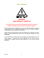
1
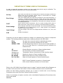
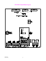
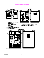
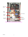
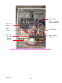
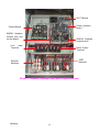
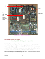
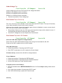
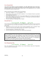
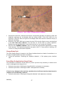
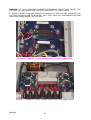
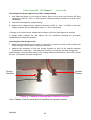
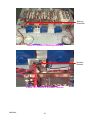
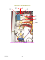
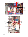
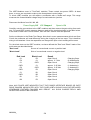
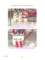
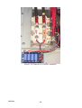
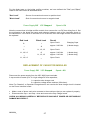
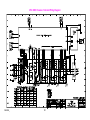
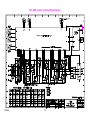
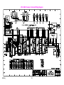
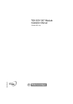
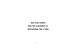
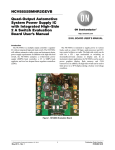
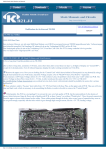
VSC
2000
SERVICE MANUAL
ZENER ELECTRIC - Manufacturers of Quality Variable Speed AC Motor Drives & Soft Starters
TABLE OF CONTENTS
USE OF THIS MANUAL ..............................................................................................................4
EQUIPMENT REQUIRED FOR SERVICING ...............................................................................4
SAFETY WARNINGS ..................................................................................................................5
DEFINITION OF TERMS USED IN THIS MANUAL .....................................................................6
SET UP FOR SERVICING.........................................................................................................12
FAULT FINDING PROCEDURES..............................................................................................13
OVER VOLTAGE (ALSO APPLIES TO UNDER VOLTAGE) TRIP, WHEN VSC STOPPED................13
OVER VOLTAGE TRIP WHEN VSC ENABLED .........................................................................14
UNDER VOLTAGE TRIP........................................................................................................15
OVER CURRENT TRIP ON POWER UP. .................................................................................15
OVER CURRENT TRIP WHEN VSC ENABLED. .......................................................................15
EARLY CURRENT LIMIT .......................................................................................................16
GROUND FAULT TRIP..........................................................................................................16
OVER TEMPERATURE TRIP ..................................................................................................16
CHARGE RELAY FAULT .......................................................................................................17
FUSES BLOW ON APPLICATION OF INPUT POWER ................................................................17
PROBLEMS WITH THE CCS .................................................................................................18
CHECKING THE DCCT BOARD ...............................................................................................18
CHECKING OUTPUT IMBALANCE...........................................................................................18
CHECKING THE CAPACITOR MODULES................................................................................18
CHECKING THE IGBT MODULES ............................................................................................22
CHECKING THE INPUT RECTIFIER MODULE ........................................................................25
REPLACEMENT OF CAPACITOR MODULES..........................................................................27
DCCT BOARD REPLACEMENT PROCEDURE........................................................................28
SENSOR WIRING REPLACEMENT PROCEDURE ..................................................................28
CONTROL BOARD REPLACEMENT PROCEDURE ................................................................28
POWER INTERFACE BOARD REPLACEMENT PROCEDURE ...............................................29
INPUT RECTIFIER REPLACEMENT PROCEDURE .................................................................29
IGBT MODULE REPLACEMENT PROCEDURE.......................................................................29
Im02004.docIM02004_: 18 May 2000
2
TABLE OF FIGURES AND PHOTOS
VSC 2000 Control Board Layout .................................................................................................7
VSC 2000 Module Locations .......................................................................................................8
Photo 1: Chassis 2 internal view without control board. ..............................................................9
Photo 2: Chassis 3 internal view with control board removed....................................................10
Photo 3: Chassis 4 internal view with covers removed. .............................................................11
CCS front panel with Touch Screen, Push-Buttons and Speed reference Pot. .........................12
Photo 4: VSC 2000 Control Board.............................................................................................14
Photo 5: VSC 2000 Temperature Sensor. .................................................................................17
Photo 6: Chassis 3 slow charge card on bus capacitors. ..........................................................19
Photo 7: Chassis 4 slow charge cards and bus capacitors........................................................19
Photo 8: Chassis 2 Sharing and Snubber resitors.....................................................................20
Photo 9: Chassis 4 Sharing resistors.........................................................................................21
Photo 10: Chassis 4 Snubber resistor .......................................................................................21
Photo 11: Chassis 2 IGBT and Rectifier terminals.....................................................................22
Photo 12: Chassis 3 IGBT terminals..........................................................................................23
Photo 13: Chassis 4 IGBT terminals..........................................................................................23
Photo 14: Chassis 3 rectifier module. First type. .......................................................................25
Photo 15: Chassis 3 rectifier module. Second type. ..................................................................25
Photo 16 Chassis 4 rectifier module. .........................................................................................26
VSC 2000 Chassis 2 Internal Wiring Diagram ...........................................................................30
VSC 2000 Chassis 3 Internal Wiring Diagram ...........................................................................31
VSC 2000 Chassis 4 Internal Wiring Diagram ...........................................................................32
IM02004_
3
USE OF THIS MANUAL
The Trouble Shooting Guide in the VSC 2000 Instruction Manual should be followed
carefully before using this manual to ensure the fault observed is not a fault external to the
VSC 2000.
This manual is intended as a guide to finding and repairing faults in the Zener VSC 2000. For
the experienced service person it provides all the information necessary to isolate a faulty
module and replace it.
This manual does not contain information regarding the repair of faulty modules as we
recommend that all faulty modules be returned to Zener Electric or an authorised distributor for
repair. This is because each module is complex and in order to be sure they function properly,
they must conform to comprehensive test specifications, otherwise further damage could result.
Procedures described in this VSC 2000 service manual should only be performed by qualified
personnel who have experience working safely with exposed high voltages and power
electronic equipment.
The following pages list faults by their symptoms. It is impossible to list every symptom
individually therefore it may be necessary to read the procedures for more than one symptom
in order to determine the best course of action.
If you are directed to check a module, refer to the Checking Procedure for that module.
If you need to replace a module, refer to the Replacement Procedure for that module.
EQUIPMENT REQUIRED FOR SERVICING
A digital or analog multimeter with the following ranges:
AC Volts up to 500 V range
DC Volts up to 1000 V range
Resistance 0 to 50,000 ohms ranges
Diode Test Range
AC current clamp meter ( 0 to 1.1 times motor name plate current)
A typically suitable multimeter is a Fluke 77.
A typically suitable clamp meter is a Iso-tech ICM39
An Electronic Insulation Tester (1000Vdc)
Slotted and Phillips head screwdrivers.
M4 (7mm AF), M5 (8mm AF) and M6 (10mm AF) Socket Drivers.
Appropriate footwear
Face shield or safety glasses
A good working knowledge of these tools is very important.
IM02004_
4
SAFETY WARNINGS
DANGER
HIGH ENERGY CIRCUITS
For safety, keep covers closed and properly secured or wear face
shield if working inside the enclosure with power applied.
The VSC 2000 contains voltage levels in excess of 700 Vdc. Standard electrical
safety guidelines are to be adopted at all times when ever AC power is applied to
avoid electric shock or damage to the VSC 2000.
Before doing any work inside the VSC 2000, always be sure that the AC power
supply is safely disconnected and that the DC Capacitor Modules are fully
discharged.
It is essential that all components in the VSC 2000 are installed whenever the AC
power supply is connected. DO NOT OPERATE the VSC 2000 with any
components or modules removed unless directed to do so by the service
procedure.
IM02004_
5
DEFINITION OF TERMS USED IN THIS MANUAL
In order to keep this procedure concise, we have used terms which may be unfamiliar. The
following list defines these terms for our service procedure.
DC Bus
Also known as the DC link, this is simply the AC mains input supply rectified and
filtered ready for the transistor inverter stage to convert back to a variable
frequency, variable voltage AC supply.
Bus Voltage
This is the voltage level of the DC bus as measured on the output transistors . It
is approx. 1.41 times the input line-to-line voltage. During motor regeneration
(over-hauling loads) the DC Bus Voltage may rise above this nominal level. The
Over Voltage protective circuit disables the VSC 2000 if this voltage rises above
an internal preset level.
DCCT
Direct Current Current Transformer. This is a current sensing device which is
able to sense DC current levels in a conductor, while still maintaining isolation.
Earth leakage
Earth Leakage is detected via the DCCT board. The current transformer senses
an imbalance in the current flowing in the 3 output phases. Any imbalance
indicates a fault current to Earth.
Input Voltage
The input voltage is the line-to-line voltage between terminals L1-L2, L2-L3, and
L1-L3.
PCB
Printed Circuit Board
Frequently you will be asked to measure a voltage on a particular plug, socket or component
network. The following definitions apply when measuring values in the VSC 2000.
Plug
Socket
SIGNAL COM.
The part of the connector which is attached to the wires.
The part of the connector soldered into the PCB.
Control Board Power Ground. Use the screw head available on
top of the Data Card as a convenient ground reference for
measurements.
JS
JF1 thru 5
JT1 thru 16
L1, L2, L3
M1, M2, M3
U+/-, V+/-, W+/-
Chassis Resistor connector on Power Interface board.
Fan connectors on Power Interface board
Temperature Sensor connectors on Power Interface board
Supply Line inputs on Power Interface board
Motor Output inputs on Power Interface board
Gate drive output signals on Power Interface board
JI
JC
DCCT Current Feedback connector on Control board.
CCS (Control Station) connector on Control board.
Refer to the VSC 2000 Control Board Layout on page 7 and the Internal Wiring Diagrams at
the back of this manual for the location of each of these connectors on the control board.
Where the fault finding procedure instructs you to check a module refer to the Checking
Procedures at the end of theFault Finding Procedure section.
When it is necessary to replace a module, refer to the Module Replacement Procedures at the
end of this manual.
IM02004_
6
VSC 2000 Control Board Layout
IM02004_
7
VSC 2000 Module Locations
IM02004_
8
Gate Drive
Boards
IGBT
Module
DCCT Board
Rectifier
Module
Bus
Capacitor
Line Input
Terminal
Motor Output
Terminal
Photo 1: Chassis 2 internal view without control board.
IM02004_
9
Slow Charge
Boards mounted
on Bus capacitors
Gate Drive
Boards
IGBT
Module
DCCT Board
Line Input
Terminal
Motor Output
Terminal
Rectifier
Module
Photo 2: Chassis 3 internal view with control board removed.
IM02004_
10
DCCT Board
Power Interface
Board
Control Board
SMPS1: Supplies
internal fans and
control board
SMPS2: Supplies
heatsink fans
Line
Input
Terminal
Motor Output
Terminal
IGBT
Modules
Rectifier
Modules
Photo 3: Chassis 4 internal view with covers removed.
IM02004_
11
SET UP FOR SERVICING
For ease of servicing we recommend that you use the MANUAL mode of operation by pressing
the MAN push-button on the CCS front panel. You can then use the FWD and STOP pushbuttons and the SPEED pot to operate the VSC 2000 during tests.
Note : To allow Manual operation the enable terminals must be linked (terminals 40 to 48) on
Control Inputs.
CCS front panel with Touch Screen,
Push-Buttons and Speed reference Pot.
In each step of the service procedures a "Status Line" will be given as shown below:
Power Supply Off
VSC Stopped
Speed = 0%
It is important that you observe this line and use the settings as indicated throughout the
procedure to obtain the correct result at each step.
Power Supply On
Power Supply Off
VSC Stopped
VSC Started
Speed = 0% to 100%
Mains AC supply IS connected to L1,L2,L3.
Mains AC supply IS NOT connected to L1,L2,L3.
Stop LED is ON.
FWD or REV LED is ON.
Setting of speed control potentiometer.
0% = zero speed, Pot Counter Clockwise
100% = full speed, Pot Clockwise
IM02004_
12
FAULT FINDING PROCEDURES
Over Voltage (also applies to Under Voltage) Trip, when VSC Stopped
Power Supply On
VSC Stopped
Speed = 0%
A over voltage trip will occur when the DC bus voltage exceeds:
400Vdc on A (240Vac) series controllers
800Vdc on G (480Vac) series controllers
1000Vdc on J (600Vac) series controllers
Check Supply Voltage
• Measure the Input Voltage at L1, L2, L3 and check that it is within the nameplate voltage
specification of the VSC 2000.
If Ok check internal causes:
Check input/bus voltage sensing as follows:
• From the CCS menu select Meter Readouts
• Check the DC bus voltage reading, Vdc. It should be approx. 1.4 x Input voltage.
• If not measure the DC Bus voltage on the DC bus bars on the Output IGBTs. It should be
approx.1.4 x Input voltage If the DC bus voltage is wrong, check the Input Rectifiers.
• If the CCS reading is wrong do the following checks:
• Measure the voltage at pin 7 on IC 55 on the Control Board with respect to the SIGNAL
COMMON on the Control board. (See Definition of Terms).
• This should equal the measured DC bus V/ 100 for A series (240Vac) controllers.
V/ 200 for G series (480Vac) controllers.
V/ 250 for J series (600Vac) controllers.
If not, check the Power Interface board and it's wiring for damage and replace it if
necessary.
• If the voltage at PIN 7 is correct, replace the Control Board following the procedure “Control
Board replacement”.
IM02004_
13
JI
IC55
Eprom.
VSC 2000
CTL
Data Card
Eprom.
VSC 2000
PWM
Photo 4: VSC 2000 Control Board.
Over Voltage Trip when VSC Enabled
Power Supply Off
VSC Stopped
Speed = 0%
Check the DC bus smoothing circuit:
• Locate the Capacitor Module(s) and the slow charge relay(s) on them. If the VSC 2000 is a
chassis 2 size, the slow charge relays are located on the Power Interface board.
• Turn on the AC Power Supply and check that ALL the relays energise approximately 2
seconds after power is applied.
• Check relays are energised by measuring for closure of the relay contacts with the
multimeter, ie zero volts across the relay contacts (terminals Bus+ and Cap+).
If any of the relays do not energise replace the Cap Charge board (power interface board on
chassis 2) immediately or further damage may result.
IM02004_
14
Under Voltage Trip
Power Supply On
VSC Stopped
Speed = 0%
Under voltage trips will occur when the DC bus voltage falls below:
239Vdc for A (240Vac) series controllers
397Vdc for G (480Vac) series controllers
505Vdc for J (660Vac) series controllers
•
Follow the procedure ”Over Voltage trip”.
Over Current Trip on Power Up.
Power Supply On
VSC Stopped
Speed = 0%
The over current trip circuit consists of the control card and DCCT board. This trip will normally
occur when excessive current to the motor is sensed.
Whenever the controller (hence the transistor gate drivers) is disabled no motor current should
flow. If an over current occurs in this state:
•
Select Meter Readouts from the CCS menu and check the Amps which should be zero. If
not follow the procedure“Checking the DCCT board”.
•
If the DCCT voltages are correct replace the Control board.
Over Current Trip when VSC Enabled.
Power Supply On
VSC Started
Speed > 0%
Check the VSC 2000 output for voltage balance:
Power-down the VSC 2000 and disconnect motor wiring from terminals M1, M2, M3.
Power-up the VSC, enable and run at 100% speed.
If the VSC 2000 trips:
• Follow the procedure “Checking the DCCT board”.
• If the DCCT board tests to be OK, replace the Control board.
If it does not trip, measure M1, M2, M3 for voltage balance.
If out of balance:
• Follow the procedure ”Checking the IGBT Modules”.
• Follow the procedure “Checking the Input Rectifier Modules”.
• If all are OK replace the Power Interface board.
If outputs are not out of balance:
• With VSC disabled select METER READOUTS on the CCS and Amps reading which should
be zero.
• If not, follow the procedure “Checking the DCCT board”.
• If the VSC 2000 still trips, replace the Control board.
IM02004_
15
Early Current Limit
The Current Limit setpoint is customer adjustable. If the VSC 2000 displays early current limit,
ensure the correct motor settings are entered in the VSC 2000 and the motor is the within
specified range for the size of VSC 2000 controller used. This is typically from 0.5 to 1.5 times
the controllers continuous rated current.
Early current limit may be caused by any of the following:
•
Check input voltage on L1, L2, L3 for balance +/- 3%.
•
Check output current on M1, M2, M3 for balance. If out of balance follow the procedure
“Checking Output Imbalance”.
•
Select Meter Readouts on the CCS. If the Amps reading does not agree with measured
motor current readings then follow the procedures to “Checking the Input Rectifier Modules”
and “Checking the Capacitor Modules”.
•
Follow the procedure “Checking the DCCT board”.
Ground Fault Trip
Power Supply Off
VSC Stopped
Speed = 0%
The ground fault circuit is located on the Control board and DCCT board. The sum of all three
motor currents at any one instant (as sensed by the DCCT) will be zero unless there is a
ground fault.
•
Disconnect the motor from the motor output terminals M1,M2,M3. Use an Insulation Tester
(1000 V) to check the motor cables and the motor insulation to ground (earth).
•
Follow the procedure “Checking the DCCT board“.
•
If the VSC 2000 still trips on Ground Fault replace the Control board.
Note: Variable Speed Drives with excessive motor cable lengths may have ground fault trips
due to the capacitance of the motor cabling. Due to the high switching frequencies in the output
voltage waveform, the motor cable capacitance causes some current to flow to earth and this
may result in ground fault trips with longer (>40m) cables. This can be reduced by selecting the
lowest AUDIBLE FREQUENCY of 2 kHz for output switching frequency, or if necessary by
fitting chokes on the output to reduce the dV/dt of the power waveform.
This phenomenon can also disrupt the operation of external earth leakage devices.
Over Temperature Trip
Power Supply On
VSC Stopped
Speed = 0%
The over temperature trip circuit consists of the Power Interface board and Temperature
Sensors located on each heatsink.
IM02004_
16
Photo 5: VSC 2000 Temperature Sensor.
•
Check that all the fans, external and internal, are operating properly and that the vents and
heatsinks openings are not blocked with any foreign matter. If the VSC 2000 is in an
enclosure, check all filters and grills for blockages and check that the enclosure fan(s) (if
fitted) are operating.
•
Each fan in the VSC 2000 can be tested via the CCS using the Service menu as described
in the VSC 2000 User’s Manual. Turn the fans on via the CCS to confirm operation.
Replace any non-operable fans, or fans that are noisy or not running at full speed.
•
Use the CCS THERMAL DISPLAY menu to check the temperatures registered by of each
of the sensors. The heatsink temperature trip point is 90 °C. If any sensor is showing 127
°C then it is faulty and should be replaced.
Charge Relay Fault
The Slow Charge Relay is located on the Power Interface board on chassis 2 controllers or on
the Slow Charge boards for all other controllers.
•
Follow the procedure “Checking the Capacitor Modules”, if OK replace power interface
card.
Fuses Blow On Application of Input Power
This indicates an excessive current draw on power up which may caused by a internal short
circuit or damaged slow charge circuit.
•
Follow the procedure “Checking the Input Rectifier” and replace as necessary.
•
Follow the procedure “Checking the IGBT” and replace as necessary.
If there is any damage to the transistor module(s) then the Power Interface board must be
replaced as a precautionary measure.
•
Follow the procedure “Checking the Capacitor Modules” and replace as necessary.
IM02004_
17
Problems with the CCS
•
Ensure that the EPROM in the CCS is the correct revision level to suit those in the Control
board. Refer to Application note IM 10005.
•
If the CCS is flashing replace the CCS.If the CCS continues to flash replace the Control
board.
•
If the CCS is blank check the +24 volt supply (located on customer terminal strip).
•
If the +24volt on the Control board is OK, check the CCS cable, if OK replace the CCS.
•
If the 24 volt supply is not present, replace the Power Interface board for chassis 2 and 3,
or the Power Supply board (SMPS 1) in chassis 4.
CHECKING THE DCCT BOARD
The Direct Current Current Transformer (DCCT) is used to sense motor current.
Measure the current feedback signals from the DCCT at JI on the on the Control board. With
respect to SIGNAL COMMON, JI pins 5,7,9 on the right hand most side at the back of the
connector should each be 2.5 V +/- 0.1 V dc.
If not, replace the DCCT board.
CHECKING OUTPUT IMBALANCE
Output imbalance trip indicates motor current and/or voltage is out of balance.
•
Check motor current balance (within 10%).
•
Check motor voltage balance(motor connected or disconnected).
If the output voltage balance is OK:
•
Follow the procedure “Checking the DCCT”.
If voltage is balanced and currents are not check motor cables and windings.
If unable to check motor current and voltage balance due to “Output Imbalance Trip”.
• Power down the VSC 2000 and disconnect the motor.
• Power up and enable the VSC 2000 and run to 50hz. Measure M1, M2, M3 for voltage
balance.
If out of balance by more than 5%:
• Follow the procedure “Checking the IGBT Modules”.
• Replace the Power Interface Board.
• Follow the procedure “Checking the Input Rectifier Module”.
CHECKING THE CAPACITOR MODULES
The DC bus capacitors are used to smooth ripple on the DC bus. This configuration
incorporates a slow charge circuit used on “power up” and capacitor voltage share resistors.
The voltage share resistors are also used to discharge the DC bus capacitors.
IM02004_
18
WARNING - IF THE CAPACITOR MODULE'S DISCHARGE CIRCUIT HAS FAILED, THE
VOLTAGE ON THE CAPACITORS WILL NOT DISCHARGE TO A SAFE LEVEL.
IF THERE IS MORE THAN ONE CAPACITOR MODULE IN THE VSC 2000, MEASURE THE
VOLTAGE ON EACH ONE TO BE SURE THAT THEY HAVE ALL DISCHARGED BEFORE
DOING ANY WORK INSIDE THE VSC 2000.
Photo 6: Chassis 3 slow charge card on bus capacitors.
Photo 7: Chassis 4 slow charge cards and bus capacitors.
IM02004_
19
Power Supply Off
VSC Stopped
Speed = 0%
Checking the DC buss capacitors and their voltage sharing:
•
Use diode test range on your meter to ensure there is not a short circuit across DC buss
capacitors (+CAP to - and + to -BUS) and the reading steadily increases till an open circuit
is indicated.
•
Check DC bus capacitor voltage sharing:
•
Measure the voltages across capacitor terminals (+CAP to - and + to -BUS) on the slow
charge card and ensure readings are within +/- 10% of each other.
If sharing is not correct check voltage share resistors (20k ohm) and replace as required.
If voltage share resistors are OK replace DC bus capacitors following the procedure
“Replacement of Capacitor Modules”.
Checking the slow charge circuit:
•
Make sure the small plug-in connector is secured in it's socket on each of the modules and
that all wiring to each module is properly connected.
•
Measure the resistance of the slow charge resistors on each of the modules between
terminals Bus + and Cap +. They should be 33 ohms if not replace the slow charge card.
Approximately 2 seconds after power up the voltage measured across Bus + and CAP+ should
be zero, if not replace the slow charge card.
Snubber
Resistor
Sharing
Resistors
Photo 8: Chassis 2 Sharing and Snubber resitors.
Not:e: Chassis 3 has the same layout of resistors but a greater quantity.
IM02004_
20
Sharing
Resistors
Photo 9: Chassis 4 Sharing resistors
Snubber
Resistor
Photo 10: Chassis 4 Snubber resistor
IM02004_
21
CHECKING THE IGBT MODULES
B2
E2
E1
B1
C1
E2
C2E1
Photo 11: Chassis 2 IGBT and Rectifier terminals.
IM02004_
22
B2
E2
B1
E1
C1
E2
C2E1
Photo 12: Chassis 3 IGBT terminals.
B2
E2
C2E1
E1
E2
B1
C1
Photo 13: Chassis 4 IGBT terminals.
Note: Each IGBT has the same type of terminal.
IM02004_
23
The IGBT Modules come in "Two-Pack" modules. These contain two power IGBTs. At least
three, or more, are required to make up the three phase inverter bridge.
To check IGBT modules you will require a multimeter with a "diode test" range. This range
measures the forward biased voltage drop of a semiconductor junction.
Disconnect the Motor from M1, M2, M3.
Power Supply Off
VSC Stopped
Speed = 0%
Carefully note the connections to the IGBT modules and then remove the gate wiring from each
one. For each IGBT module measure between each of the terminals shown in the table below.
If the result of each test is not as shown, then the IGBT module must be replaced.
Set the multimeter to the Diode Test Range. Note that in some measurements which are Open
Circuit the multimeter will read differently during the charging of the bus caps. This is because
wiring is still attached. Once the capacitors are charged the open circuit reading will be seen.
For the diode tests on the IGBT modules, we have defined the "Red" and "Black" leads of the
multi-meter as described below.
"Red Lead"
Source of conventional current or positive lead
"Black Lead"
Sink of conventional current or negative lead
Red Lead
Black Lead
C1
E2
C1
C2E1
E2
C2E1
C1
C2E1
B1
B2
E2
C1
C2E1
C1
C2E1
E2
B1
B2
E1
E2
Result
Open Circuit
approx. 0.7 Vdc
Open Circuit
approx. 0.35 Vdc
approx. 0.35 Vdc
Open Circuit
Open Circuit
Open Circuit
Open Circuit
Open Circuit
Charging Caps.
(2 diode drops)
Charging Caps.
(1 diode drop)
(1 diode drop)
Charging Caps.
Note: ANY FAILED IGBT INDICATES THAT THE POWER INTERFACE BOARD OR GATE
DRIVE BOARDS ASSOCIATED WITH THE FAILED IGBTs SHOULD ALSO BE REPLACED
OTHERWISE FURTHER FAILURES MAY RESULT. ALL SLOW CHARGE RELAY AND
RESISTORS SHOULD BE CHECKED.
IM02004_
24
CHECKING THE INPUT RECTIFIER MODULE
Photo 14: Chassis 3 rectifier module. First type.
Photo 15: Chassis 3 rectifier module. Second type.
IM02004_
25
Photo 16 Chassis 4 rectifier module.
IM02004_
26
For the diode tests on the bridge rectifier modules, we have defined the "Red" and "Black"
leads of the multi-meter as described below.
"Red Lead"
"Black Lead"
Source of conventional current or positive lead
Sink of conventional current or negative lead
Power Supply Off
VSC Stopped
Speed = 0%
Note the connections to bridge rectifier module, then remove the +ve DC bus wiring from it. Set
the multimeter to the diode test range and measure between each of the terminals shown in
the table below. If the result of each test is not as shown, then the bridge rectifier module must
be replaced.
Red Lead
Black Lead
Result
+
-
+
Open Circuit
Charging Caps.
approx. 0.80 Vdc
(2 diode drops)
+
L1, L2, L3
Open Circuit
L1, L2, L3
+
approx. 0.40 Vdc
(1 diode drop)
-
L1, L2, L3
approx. 0.40 Vdc
(1 diode drop)
L1, L2, L3
-
Open Circuit
REPLACEMENT OF CAPACITOR MODULES
Power Supply Off
VSC Stopped
Speed = 0%
Disconnect the power supply from the VSC 2000 input terminals.
A cap module is made up of: 2 x high voltage DC bus capacitors;
1 x capacitor slow charge card
2 x capacitor voltage share resistors (20k ohms).
Note: For Chassis 2, a Capacitor Charge board is not used as the slow charge circuit is located
on the Power Interface board.
•
Make a note of where each wire connects to the module so that you can replace it properly.
•
Disconnect the Cap + and Cap - wires and remove the Cap Charge board.
CHECK ALL WIRING CAREFULLY BEFORE APPLYING INPUT POWER OR IGBT MODULE
DAMAGE MAY RESULT.
IM02004_
27
DCCT BOARD REPLACEMENT PROCEDURE
Power Supply Off
VSC Stopped
Speed = 0%
VSC 2000 controllers fitted with B1007xx DCCT cards:
•
These cards and wiring are a calibrated sub assembly which MUST be replaced in its
entirety. Make a note of the wiring connections before removing the existing wiring and
DCCT board.
Remove wiring and DCCT subassembly and replace with the new one, reconnecting as before.
This completes the installation of the new DCCT.
VSC 2000 controllers fitted with L.E.M. DC current sensing devices (chassis 4 and up):
•
DCCT card B1040xx is a plug in replacement.
SENSOR WIRING REPLACEMENT PROCEDURE
Power Supply Off
VSC Stopped
Speed = 0%
The Sensor Wiring consists of the temperature sensors - connector JT.
Carefully observe the location, mounting and connection of the sensing wires.
•
Remove the Temperature Sensor by withdrawing it out from lug holding it to the heatsink
and unplug the connector JT from the Power Interface board.
• Remove the bus sensing wires, noting carefully where they connect.
Now the old Sensor Wiring may be removed.
Fit the new Sensor in reverse to the removal procedure. Ensure segregation from High Voltage
circuits is maintained.This completes the replacement of the Sensor Wiring.
CONTROL BOARD REPLACEMENT PROCEDURE
Power Supply Off
VSC Stopped
Speed = 0%
•
Remove all the plugs,earth wire and terminal strips from the control board with all the field
wiring still in place in the terminal strip.
•
Remove the two EPROMS and the data card.
• Remove all ten mounting screws from the control board.
Fit new control card in reverse procedure.
CHECK THAT ALL THE TERMINALS AND EPROMS HAVE BEEN RE-INSERTED
PROPERLY. MAKE SURE NONE OF THEM ARE DISPLACED BY ONE PIN.
IM02004_
28
POWER INTERFACE BOARD REPLACEMENT PROCEDURE
Power Supply Off
VSC Stopped
Speed = 0%
Ensure the power interface board is replaced with a board of identical assembly number
to the original.
•
Note carefully the wiring colour codes and their points of connection as there is quite a
number of connections to be handled in replacing the board.
•
When board replacement is completed, check all the new connections against the notes
you made to ensure they are all correct.
INPUT RECTIFIER REPLACEMENT PROCEDURE
Power Supply Off
VSC Stopped
Speed = 0%
Note carefully the orientation of the rectifier module(s) on the heatsink. Also note the
connections to the module.
•
Remove the mounting screw(s) from the module and lift it from the heatsink.
•
Apply a light smear of heatsink grease to the base of the new module and place it on the
heatsink in the same position as the old module.
•
Replace the mounting screw(s) and re-connect the wires carefully.
IGBT MODULE REPLACEMENT PROCEDURE
Power Supply Off
VSC Stopped
Speed = 0%
Before removing the old IGBT module, make a note of all the connections to it. Pay
careful attention to the connection of the Gate Drive wires.
Chassis 2 : IGBT’s have a zener diode soldered across Gate/Emitter.
Chassis 3 : IGBT’s have a zener diode soldered across Gate/Emitter.
Chassis 4 : the gate drives are connected via small printed circuit boards mounted on
top of the IGBT.
•
Remove the wires and bus bars from the IGBT module.
• Remove the mounting screws from the modules.
Apply a thin smear of heatsink grease to the base of the modules and place the IGBT back on
the heatsink.
•
Insert and tighten the mounting screws.
•
Replace the wiring and check carefully.
IF YOU REPLACE A FAULTY IGBT YOU MUST ALSO REPLACE THE POWER
INTERFACE BOARD OR FURTHER DAMAGE MAY OCCUR.
IM02004_
29
VSC 2000 Chassis 2 Internal Wiring Diagram
IM02004_
30
VSC 2000 Chassis 3 Internal Wiring Diagram
IM02004_
31
VSC 2000 Chassis 4 Internal Wiring Diagram
IM02004_
32