1
A.C.E
WASHER DISINFECTOR
OPERATING INSTRUCTIONS
& SERVICE MANUAL
SERIES 2000 K-Ol
,---------
----------------~
INDUSTRILEX MANUFACTURING PTY LTD
FACTORY 7, 91-99 BERESFORD ROAD
p.a. BOX 189 LILYDALE
VICTORIA AUSTRALIA
TELEPHONE: 03 9735 1673 FAX: 03 9739 6490
OPERATING INSTRUCTIONS & SERVICE MANUAL
CONTENTS
PAGE
HiSIALLATION INSTRUCTIONS
ELECTRICAL CONNECTIONS
PLUMBING REQUIREMENTS
DRAINHOSE CONNECTION
PREPARING THE UTENSIL WASHER
SECURING THE UTENSIL WASHER FOR HEAVY LOADS
2
2
3
3-4
4
OPERATING INSTRUCTIONS
OPERATION & LOADING OF MACIDNE
5
PERIODIC MAINTENANCE
CLEANING MACHINE CASING
CLEANING SPRAY ARMS & DRAIN CUP
CLEANING WASH FILTERS
CLEANING INLET WATER FILTER
6
6
7
8
BEFORE CALLING SERVICE
9
UTENSIL WASHER WARRANTY
10
SERVICE INSTRUCTIONS
SPECIFICATIONS
ELECTRONIC CONTROL TEST FACILITY
PROGRAMME ELECTRONIC CONTROLLER
WIRING DIAGRAM
TROUBLE SHoarING GUIDE
11-16
17
18
19
20-22
REMOVAL OF PARTS
OUTER IXX)R PANEL
DETERGENT DISPENSER
CONTROL PANEL
MEMBRANE SWITCH
23
POWER CONTROL BOARD
IXX>R SAFEIT SWITCH
27
28
24
25
26
EXTERIOR PANELS
STAINLESS STEEL lX)()R LINER
IXX)R HINGE SPRING & PUSH ROD GUIDES
IXX>R HINGES
UPPER BASKET RAIL & WHEEL GUIDES
TUB GASKET
PRESSURE SWITCH & ADJUSTMENT FOR WATERLEVEL
29
30
31
32
33
34
35
36
37-40
41-43
SUMP
WASH MOTORJPUMP ASSEMBLY
DRAIN PUMP
PARTS LISTS
EXTERIOR PANELS & CONTROL PANEL PARTS
IX>OR COMPONENTS
WASHTUB & ELECTRICAL COMPONENTS
SPRAY ARM, FILTERS & OVERFLOW SYSTEM
WASH MafOR & DRAIN PUMP
HOSES
BASKETS
- 1
44-45
46-47
48-49
50-51
52-53
54-55
56-58
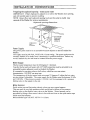
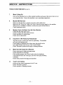
INSTALLATION INSTRUCTIONS
Preparing the cupboard opening· Undercounter model
IMPORTANT: Ifbare chipboard is adjacent to or above the Washer door opening,
seal with suitable paint to prevent swelling.
NOTE: Ensure floor and cupboard opening levels are the same to enable easy
removal of the Washer for service requirements.
Cu·pboard opening dimensions.
Cui ouls for
hoses and
electrical
cables on
All dimomions
oro in
miJlimolros.
Power Supply
The power point must be in an accessible location adjacent to and not behind the
Washer.
The supply must be 240 Volt, 50 HZ with 15 Amp rating. The power point must be
correctly earthed, if in doubt, have it checked by a qualified electrician. Before any
work is carried out, the unit must be isolated from the power supply.
Water Supply
The hot water temperature must be 60 degrees C minimum.
Taps for the hot and cold water with 3/4" BSP connection must be provided in an
accessible location adjacent to and not behind the Washer.
It is essential to use gate valves or ball valves, which have no non-return
characteristics. DO NOT use stop taps.
The temperature of the hot water must not exceed 75 degrees C, adjust the hot water
service setting if adjustable. The water supply for the Washer must be between 30 kPa
and 1100 kPa. If the pressure exceeds 1100 kPa it will be necessary to fit a pressure
limiting valve in the supply to the unit.
Water Hammer
Quick action taps and fast acting electric valves can cause water hammer.
This can result in very high pressures which could lead to failure ofthe pressure
limiting valve or the electric water valves to the Washer. Water hammer can be
prevented by fitting a flow control valve in line with and close to the quick action taps
which cause the hammer.
Recommended type is R.M.C. MP 50 10-12 litres.
2.
INSTALLATION INSTRUCTIONS
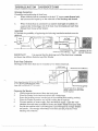
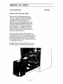
Drainage Connection
Connection and positioning of drain hose.
a.
When the drain hose is connected to the sink'S' trap or waste disposal unit,
the hose must be looped up to the underside of the benchtop and secured.
b.
When the drain hose is connected to a seperate stand pipe or tundish, it is
essential that the discharge end of the drain hose terminates not lower than
600mm from the top of the Washer.
Important
To prevent the possibility of syphoning the following installation methods must be
observed.
/:';~l;¥
. Air Tight
conneclion ~
1-=-~=-=1
~_-I'I
809 -o"'OcgCZlU"lT£R
/300
FlZeE STANDI"C
300
300mm Min.
min.
All dimomions oro In mlllimolros.
.".-..
<f-Slondpipe 40 mm
diomeler minimum•
WPORTANT:
It is essential that the discharge end of the drain hose terminates
not lower than 600mrn from the top of the Washer.
Drain Hose Extension
The length ofthe drain hose can be extended by two meters maximum.
2000 mox.
,All dimonsions oro In mlllimolrQs.
300 min.
Drain hoso EXfension Kit Port No.7801-1l94
or 16 ·20 mm inside diameter rubber
hose able lo wilhstond 90°C hot waler
Drain Hose (slJpp1ied)
r
Copper Pipe 20mm diameter
flared at drain hosa and other
end if required
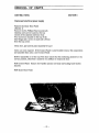
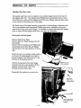
Preparing the Washer
1.
2.
3.
4.
5.
Unclip hoses and powercord from the back panel.
Place the Washer on its back and remove the wooden base.
Screw the levelling screws into the legs of the machine (free standing models).
Place the Washer in position and adjust levelling feet if required.
Connect machine to water supply, drain and electric supply. Open the wash
chamber door and remove cardboard inserts and elastic bands from spray arms.
Provide the machine with liquid detergent, Liquid detergent is strongly alkaline
and caustic. We strongly recommend to use skin and eye protection when
handling this substance.
3.
INSTALLATION INSTRUCTIONS
Preparing tile Washer (Cont'd)
6.
The recommended Liquid Detergent is "MEDIGLEAM."
It is available in 5 litre containers from Whiteley Industries Pty Ltd.
Telephone (02) 99299155.
Detergent provision for Freestanding Models
Open the bottom door of the machine and place the liquid detergent container on the
floor in front of the bottom tray. Remove the cap of the container and insert the
stainless steel tube carefully, place the container inside the machine and close the door.
Detergent provision for Undercounter Models
Position the Liquid Detergent container in a cupboard next to the machine or in a
convenient location close to the machine. Remove the cap of the container and insert
the stainless steel tube which is stored at the back of the Washer. The plastic tube can
be shortened to suit if necessary.
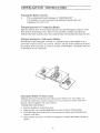
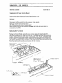
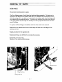
Securing the Washer for Heavy Loads
Although both the Freestanding and Undercounter Washers are very stable, we
recommend where heavy loads are likely to be encountered, to use the lock down
bracket which is supplied with each machine.
To install lock down bracket:
• Position machine in required position.
• Place bracket over rear levelling foot and mark positions of fixing holes.
• Drill and insert 8mm dyna bolts or use woodscrews where required and secure
bracket to the floor.
• Slide machine in position levelling foot engaged in bracket and insert lock pin as
shown.
4.
OPERATING INSTRUCTIONS
1.
2.
3.
4.
5.
6.
Check that electric power is on.
Check that the Hot and Cold water taps are turned on.
Open the door, this can only be done when the "power on" light is illuminated.
Ensure no objects are left on utensils to be loaded into the machine, i.e. cotton
wool etc. Load the utensils in the baskets.
The bottom basket can accommodate 6 wash bowls, these are stacked
vertically. The top basket is used for tooth mugs, sputum bowls, kidney bowls,
etc. these should be placed upside down so that all water will drain freely from
the articles.
Ensure there is sufficient liquid detergent available in the machine or place a
heaped tablespoon of powder detergent in the dispenser in the door.
Close the door and press "Start". The programme will commence. While the
machine is in operation the door cannot be opened.
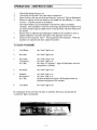
THE WASH PROGRAMME
1.
Cold Rinse
the "rinse" light is on.
2.
Hot rinse
the "rinse" light is on.
3.
Hot Wash
55 degrees C
for 2 min.
the "wash" light is on.
the "heat" light is on.
the "temp. 55 degrees C" light will illuminate when the
temperature is reached.
4.
Hot Rinse
the "rinse" light is on.
5.
Disinfect
80 degrees C
for 5 min.
the ''final'' light is on.
the "heat" light is on.
the three temperature lights will illuminate when the
indicated temperatures are reached.
6.
Cold Rinse
the "rinse" light is on.
On completion of the cold rinse, the door is unlocked, the buzzer sounds and the
"completed" light is illuminated.
- 5
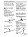
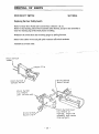
PERIODIC MAINTENANCE
Cleaning the machine casing Inside
Removing the upper spray arm
Use recommended stainless .steel cleaner to
keep the inner lining in "as new" condition.
Wipe the rubber door seals over occasionally,
including the seal at the bottom of the door.
To remove the Upper Spray Arm, pull the
upper basket out. Detach the clip on the right
hand side of plastic tower which holds it to the
basket. Be careful not to trap your fingers.
Remove complete assembly from the
underside of the basket.
Alternatively, carefully unscrew the spray arms
from the plastic tower. To achieve this, hold
the inner tower steady and unscrew the spray
arm clockwise. To replace the spray arm
carefully screw the spray arm anticlockwise on
to the inner tower.
Cleaning the machine casing Outside
Wipe over occasionally with a soft damp cloth.
NEVER use acids, abrasive cleaners or
detergents.
Removing the spray arms
Every so often, it's worth removing and
cleaning the spray arms to make sure that none
of the holes have become blocked.
Removing the lower spray arm
To remove the Lower Spray Arm, grasp the
centre of the spray arm and pull upwards, it
will simply unclip. When replacing make sure
it is fully clipped down.
t
.
Cleaning the Spray arms
To clean both the upper and lowel: spray arms
rinse under running water. Ensu~e all spray
holes are clear, if necessary unblock spray
holes with a wooden kitchen skewer or the
like.
To replace the spray arms reverse the above
procedure
Pull up
to remove
Removing the drain cup
The plastic nozzle on the underside of the
spray arm can be detached simply by
unscrewipg anticlockwise
r
Rotate anticlockwise to
remove nozzle
The drain cup is located in the stainless steel
filter at the base of you machine. The drain
cup is used to collect larger misc. items which
may be too big to pass through the drain
pump. For pest wash performance, check the
drain cup after each wash program, empty and
rinse ifnecessary.
Twist the two vertical handles anticlockwise,
rotate the drain cup and lift
to remove. To replace,
reverse these steps
making sure the
drain cup locks
into place.
Rotate anticlockwise
& lift to remove
drain cup
- 6 .
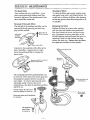
PERIODIC MAINTENANCE
The wash filters
Cleaning of filters
Your machine has two wash filters - a two
piece round p'erforated stainiess steel filter
located in the base of the machine and a finer
micro-mesh filter under this.
To clean the filters, place under running water
and gently brush with a soft bristled brush. Be
careful not to deform the filters while cleaning,
as this may prevent them from being able to be
re-installed.
Removal of the wash filters
The left half of the stainless steel filter can be
removed by firstly removing the drain cup,
grip the filter and lift.
t
Grip filler &
lift to remove
Replacing the filters
Replace the filters in reverse order, starting
with the right half stainless steel perforated
filter then replace the tower and lower spray
arm. Reconnect the micro mesh filter to the
left half stainless steel perforated filter prior to
replacing it back into the machine and then
replace the drain cup. Ensure that the filters
are replaced correctly for best ..~sults.
Attached to the underside of this filter is the
micro mesh filter. Squeeze the two clips
above the perforated filter to release the
micro-mesh.
Spray Jet
Diverter
The remaining half ofthe perforated filter can
be removed. First remove the lower spray arm
then grasp the spray jet diverter around the
outer edges. To remove pull upwards and it
will simply unclip. Unscrew the tower
anticlockwise, then grip the stainless steel filter
and lift it out.
Grasp edges & pull up to
remove spray jet diverter
t
Perforated Stainless
StecJ Fi!ters.
~~~'~===-------Micro-mesh
Barrel Filter
Unsc~ew tower
anticlockwise
to remove
Lift stainless
steel filter
to remove
t
- 7
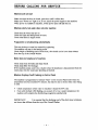
PERIODIC MAINTENANCE
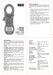
Cleaning the inlet water filters
The special filter washer, between the tap and
hose, filters all incoming water. To clean this,
first close the shut off valve, than to release
any water pressure left in the hose, select and
start the program. Allow the machine to run
for about 25 to 30 seconds, then switch off at
the power point.
Unscrew the hose connection and gently
remove the filter washer and rinse clean.
Refit the washer and hose to the shut off valve
in the reverse order, take care not to over
tighten.
The condition of the water supply hoses
should be checked periodically.
IMPORTANT: Do not use iron and non-rust
proof steel utensils in the Utensil Washer, and
do not use soap impregnated steel pads for
cleaning as this will cause rust stains on the
stainless steel interior.
Fitting filter - standard hose
ell
'-"'~.::..::....l Gale or Ball Valve
.~,
...
.
Filter
•
InletHo,e
•.,'., •.•~••~>;'. . :
.
,.;, ..•..•.•
,:,":"'y'.'.l"~""" ',•. 'r~ !
' ,......;;,
,;~
",
IMPORTANT: Ensure domed side of filter faces valve.
Hose Fitting
If this component requires replacement, it
must be replaced with the authorised service
spare part to ensure correct operation.
Fill hoses should be checked at 6 month
intervals to ensure any deterioration is
identified.
Power Cord Replacement
In the event of the power supply cord being
damaged, it must be replaced with the
authorised service part and fitted by a qualified
electrician.
When not in use for long periods
To prevent any chance of odour:
• Ensure racks are completely cleared of
utensils.
• Clean filters thoroughly. Ensure rubber
door seal is clean, also the door liner
edges, which are not cleaned by the wash
cycle.
• Turn offthe electricity and water.
• Leave the door ajar to avoid stuffiness.
- 8
BEFORE CALLING FOR SERVICE
Machine will not start
Make sure that the door is closed, press door until it clicks shut.
Make sure ''Power on" light is on, if not, check the power supply to the machine.
When power is available to machine, switch power point off and then on.
Machine starts, but water does not enter machine
Check that the water taps are on.
Check for kinks and sharp bends in hoses.
Check inlet filters in supply hoses.
Programme is not advancing automatically
This may be due to water loss caused by syphoning.
The machine will stay in the heating mode.
Check height of discharge end of drain hose, this should not be lower than 600mm
from the top of the Utensil Washer.
Water does not empty out of machine.
Check drain hose for kinks and sharp bends.
Check drain filter for blockage.
If the machine pumps water into a bucket when the drainhose is disconnected from the
waste pipe, then the waste pipe plumbing is blocked.
Machine Displays Fault Flashing on Control Panel
The machine is programmed to indicate ''fault'' on the Control Panel LED when the
programme time has exceeded 45 minutes, this may be due to the hot inlet water being
to cold:
• Check temperature ofhot water to machine it should be 60°C min.
• Even with the fault LED flashing, on account ofto Iowa water temperature the
machine will complete the disinfecting programme satisfactorily.
IMPORTANT:
It is essential that the discharge end of the drain hose terminates
not lower than 600mm from the top ofthe Utensil Washer.
- 9
STANDARD WARRANTY
(AUSTRALIA)
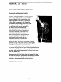
Foreword
The warranty below is to help you in the unlikely event that there is a problem with the
appliance itself We functionally test every unit using its own controls including water
fills, circulation and drain out. It would be a good practice to check your method of
operation against the operating instructions before calling out our service personnel.
Also ensure that the installation specifications have been met. Failure to do this could
result in expense to you for our service personnel attending even inside the warranty
period, where there is no fault with our product.
Utensil Washer Warranty
The benefits conferred by this warranty are in addition to all other rights and remedies
in respect of the product which the comsumer has under the Trade Practises Act and
similar state and territory laws.
Subject to the following conditions we provide from the date ofinstallation the
following warranty:
• Any part found to be defective in workmanship or material will be replaced at no
cost within the period of warranty which is 12 months. The period ofwarranty and
the condition below do not impinge upon your statutory rights which you are at
liberty to exercise as a consumer.
Conditions of Warranty
The following conditions do not preclude you from your statutory rights as a
consumer.
• Under this warranty, the unit must be installed according to the Manufacturer's
installation instructions and be connected to the correct electric power, water
supply and drainage system.
• The unit must be used in strict accordance with the operating instructions.
• A charge will be made where the failure is due to neglect, abuse or accidental
damage on the part of the operator.
• No responsibility is accepted for any loss or damage, direct or indirect, arising from
the incorrect installation or operation ofthis unit.
• The installation work perfonned on this appliance is not within the control of the
manufacturer.
If damage and incorrect operation ofthis appliance occurs due to faulty installation,
then the subsequent repair is not covered by this warranty, and any service work
required to rectify the faults is chargeable.
Industrilex Manufacturing
Factory 5.91-99 Beresford Road
P 0 Box 189 Lilydale Victoria
3140 Australia
Tel: (03) 9735 1673
Fax: (03) 9739 6490
- 10
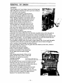
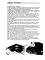
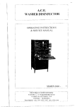
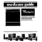
SERVICE INSTRUCTIONS
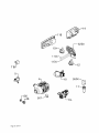
LOCATION OF MAJOR COMPONENTS
I
f'
"
.1
.'
{
!
~
f!)---I--++--~~L f)r;;;;:~
.'I:
~
1.
3.
Upper Basket Feed Pipe
Door Solenoid
2.
4.
Door Microswitch
Electronic Controller
5.
Load Collector
6.
Push Rod Guide
7.
Door Hinge, Spring & Push Rod
8.
Pressure Switch
9.
Wash Motor Capacitor
10. Overfill Spillway
11. Overfill Chamber, Cup & Microswitch Assy. 12.
Sump
13. Heater Relay
14.
15. Overtemperature Thermostat
16.
Drain Pump
Detergent Pump
17. Wash Motor Pump
18.
Heating Element - 2000 Watt
19. Water Inlet Solenoid Valve
20.
Heating Element - 1200 Watt
21. Detergent Dispenser
- 11
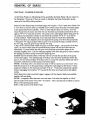
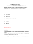
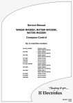
SERVICE INSTRUCTIONS
The diagram below illustrates the water flow and identifies the main components in a 3
level micro-filtration system. Note that the sump is drawn in dotted lines for illustration
purposes.
1.
~
. ~'- -
\'" -j
//
1.
Water inlet Solenoid Valve
2.
Collector
3.
Pressure Switch
4.
Sump
5.
Wash Pump water inlet via sump
6.
Wash Pump
7.
Wash Pump to Upper Spray Arm
8.
Wash Pump to Lower Spray Arm
9.
Various Lower Spray Arm water jets.
10. Lower Spray Arm water jets
11.
Spray Jet Diverter
12. Drain Pump water inlet
13.
Drain Pump
14. Water outlet to drain
- 12
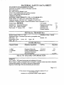
SERVICE INSTRUCTIONS
SPECI FICATlONS
DIMENSIONS OF UTENSIL WASHER
''M'' Model
Width in mm
Height in mm
Depth in mm
Electric Mains
Current Rating
Wash Pump Motor
Drain Pump Motor
Water Heating Elements
Water Volume, per fill
Inlet Water Pressure
Inlet Water Temperature
Drain Hose
"1-" Model
600
825
590
600
1310
590
240 Volt, 50 Hz AC.
15 Amps
110 Watts
30 Watts
2000 Watts & 1200 Watts
6 Litres
30 kPa min. - 1100 kPa max.
60°C min. - 75°C rnax.
19mm I.D.
Wash Motor/Pump Assembly
Part Number 8905-900 (2 outlet).
Motor Manufacturer - Webster Manufacturing Ltd.
Motor Cat No. D63V 3110
240V AC, 50 Hz, 1 PH, 0.89A.
110W, MCR CS&R, 2850rpm.
Class 130
Capacitor 6t-tF 400V
Warning: Motor is fitted with internal auto reset overload and
may restart without warning.
Resistance of winding @20°C ± 5%
Brown & Blue - 29.0 Ohms.
Blue & Black - 29.0 Ohms.
Black & Brown - 58 Ohms.
Note:
MotorlPump Assembly, part number 8905-900, has pump cover
with the two lOmm diameter spigots blanked off (2 outlets).
- 13
SERVICE INSTRUCTIONS
Water Inlet Valve
Manufacturer - Eltek
Operating Supply Pressure Range -Static Cold: 20 kPa minimum
1000 kPa maximum
Static Hot: 20 kPa minimum
500 kPa maximum
Maximum inlet supply water temperature - 65°C.
Nominal delivery flow rate from valve - 4 litres/minute.
220/240V AC, 50 Hz.
Solenoid DC resistance @20°C - 3.94 k Ohms ± 5%.
Inlet thread G 3/4" (3/4" BSP).
Electrical connection - 2 x 6.3mm x 0.8mm QC tabs.
Powder Detergent Dispenser
Manufacturer - Elbi, Type 542.
Single solenoid type with gravity latchllock mechanism.
220/240V AC, 50 Hz.
Resistance of solenoid coil @ 20°C - 1.3 Ohms ± 10010.
Total capacity of detergent chamber - 37cc.
Fluid Detergent Dispenser
2 Litre capacity with 12 Volt DC pump for 40cc
detergent injection.
Optical eye action filler cap for detergent level.
Water Heating Elements
240 VAC, 50 Hz, 2000W & 240V AC, 50 Hz, 1200 Watt.
31 Ohms 3 @ 20°C (2000W)
Insulation resistance - 20 meg Ohms (minimum).
Element sheath material- 321 stainless steel.
Mounting - stainless steel (type 302).
Flange and stud - M6 stainless steel (type 302-304).
Ends of sheath sealed with epoxy-epirez 324A.
Electrical connection - 6.3mm QC male stainless steel (type 302-304)
spade terminals.
- 14
SERVICE INSTRUCTIONS
Thermostat - Overtemp
Identification - Green Dot.
Mounting - M4 x 0.7 male thread
Electrical connection - 6.3rnm x 0.8mm QC tabs.
12SV12S0V.
Temperature specification - Close: 50°C ± 4°C.
- Open: 80°C BOC.
Pressure Switch
Main Contact Load - 16A., 240V AC.
Contacts
- Nos. 1 & 3 utilised for heater.
- Nos 1 & 2 utilised for hot & cold watervalves.
Electrical connection - 6.3mm male tabs
Nominal Calibration - set 60rnm &lO
- reset 15rnm !-k0
Operating Temperature - T85°C maximum.
Drain Pump
Manufacturer - Plaset.
Rated Input - 30W, 0.25A., 240V AC.
Resistance ofField Wmding @20°C - 166 Ohms ± 10%.
Insulation - Class F.
Nominal RPM - 3000, 2 pole motor.
Motor temperature protector field winding - 170°C trips open.
Outlet Spigot equipped with non-return flap valve.
Nominal Discharge Rate - 15.20 litres/rnin @ 1 metre head.
Micro Switch - Overfill
Manufacturer - Honeywell.
250V AC, 20A., UL approved.
85°C maximum temperature.
Switch Mode - SPDT.
Contacts - Silver CAD oxide or silver contacts.
Electrical connection - 6.3mm x 0.8mm silver plated QC tabs.
Operating Force - 70 gram.
Release Force - 10 gram.
- 15
SERVICE INSTRUCTIONS
Mains Terminal Block
Supplier - Multi Contacts Australia Pty. Ltd.
Poles - 3 marked A, N & E.
380V, 16A, from 3 x 0.75 to 5 x 1.5mm
Housing - SelfExtinguishing Black polyamide.
Temperature Rating - 125°C.
Metal Parts - Zinc Passivated Steel.
Heating Relay
MB2 240V 13 Amp.
MB2 PDT 13 Amp.
12 Volt Transformer
Arlec part number P S699
Multi-Voltage Transformer
240V 50 Hz 3-3-12V 500 mA.
Operated at 12 Volts DC.
Wash Motor Capacitor
400V AC, 50 Hz 61JF.
Type - metallised Polypropylene.
Electrical Connection - 2 x 6.3mm x 0.8mm QC tabs.
Door Solenoid
Manufacturer - ITC
Number 16 - 240V continuous.
Door Microswitch
Zippy - 10 Amp 250V
- 16
SERVICE INSTRUCTIONS
ELECTRONIC CONTROL TEST FACILITY
1.
LED Display Test
This test is useful for checking that all LED's are working.
Press the following buttons.
1st Press Temp 80°C, 2nd Power on, 3rd Temp 65°C, 4th Temp 80°C
and then Power on.
,
All the lights will go on and then one at the time to show that t~ey are working.
To cancel this mode, Switch off at electric supply and switch on again.
2.
Individual Output Control
This allows each output to be operated independently for fault finding.
1st Press Temp 80°C, 2nd Power on, 3rd Temp 65°C, 4th Temp 80°C
and then Completed.
Then each control switch operates an output as follows:
•
•
•
•
•
•
•
Completed
Temp 80°C
Temp 65°C
Fault
Power On
Operate - Start Blank (at the end)
Operates
"
"
"
"
"
"
Wash Pump
Drain Pump
Water Heater
Detergent Dispenser
Door Lock
Cold Water Fill Valve
Hot Water Fill Valve
To disable this facility and return to normal operation, switch off at electric supply and
switch on again.
- 17
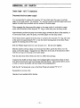
SERVICE INSTRUCTIONS
PROGRAMME ELECTRONIC CONTROLLER
Cycle
Step Time
1st PRE-RlNSE
- Cold
(Rinse LED on)
2nd PRE-RlNSE
-Hot
(Rinse LED on)
Hot Wash
(Wash LED on)
Operation
Till Full
2
3
4
2 min.
Empty +15"
Till Full
5
6
7
45 sec.
Empty + 15"
Till Full
1.20 min.
9 Till Hot
10 2 min.
11 Empty + 15"
12 Till Full
8
1st Hot Rinse
(Rinse LED on)
2nd Hot Rinse
Final LED on
Last Rinse
- Cold
(Rinse LED on)
COMPLETED
13 Till Hot
14 1 min.
15 Empty + 15"
16 Till Full
17
18
19
20
Till Hot
5 mins.
Empty + 15"
Till Full
21 45 seconds
22 Empty + IS"
23
24
25
- 18 -
Cold Fill and wash full signal.
After 15 seconds, wash motor off
for 3 seconds, then on again.
Wash.
Drain until empty + 15 sec.
Hot fill and wash until full signal.
After 15 sec. wash motor off, for
3 seconds then on again.
Wash.
Drain until empty + 15 sec.
Hot :fill and wash until full signal.
After 15 sec. wash motor off for
3 seconds. Then wash starts again
together with start of detergent disp.
Wash, Heat & Detergent release (5 sec)
Wash, Heat until 55°C is reached.
Wash.
Drain until empty + 15 sec.
Hot fill and Wash until full signal.
After 15 seconds, wash motor off for
3 seconds, then on again.
Wash & Heat until 55°C is reached.
Wash.
Drain until empty + 15 seconds.
Hot fill & Wash until full signal.
After 15 seconds, wash motor off
for 3 seconds, then on again.
Wash & Heat until 82°C is reached.
Wash and maintain 82°C temperature.
Drain until empty + 15 seconds.
Cold fill & Wash until full signal.
After 15 seconds, wash motor off
for 3 seconds, then on again.
Wash.
Drain until empty + 15 seconds.
End of cycle. Door is unlocked,
buzzer sounds, Completed LED
is lit.
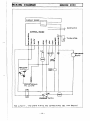
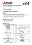
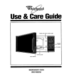
SERIES 2000,
DOOR SWITCH
eOIiT~Ol.
- BOARD
"Q
}O
ftl
~
C
.
»
11\
~
I1l
-t
f\
.....
::c
>
....
III
<.
~
t.'
C
;t
~
~
)..
IQ
~
CIl
0
f
:r: z.
'X
0
....
"00
r
~{)
TH£ICMlSTOQ.
n
7"
D
OOOR
LoeK·
H~tJ1NG ELeM~n
1NC.OI-rrt.M.P.
"..
t-----~o-t--~---......JL-.....rt_-~--L-.l-------l
2\
FOR CLARITY ~ THe EARTH WIRJNG AND CONNeCTIOHS AR~ NoT ~'·I.ol-:!.d.
- 19
SERVICE INSTRUCTIONS
TROUBLE SHOOTING GUIDE
1.
Poor Wash
Most poor wash problems are caused by insufficient water supply to the spray
arms.
Clear any obstruction from the spray arms. Check cleanliness of the wash
filters.
Check the upper spray arm nozzle for any blockage. Top spray arms only have
jet holes on the top and a small drain hole on the underside.
Use a clear glass or plastic panel the size ofthe door opening to allow a clear
view of the spray arms in operation.
Check top basket venturi cone lines up with delivery nozzle in top of tub.
BOTTOM SPRAY ARIv1, jets should easily reach top of the liner, with
substantial force when empty.
TOP SPRAY ARM. during this test cover bottom basket area with heavy
dishes or pans. Jets from top spray arm should easily and forcefully reach the
top ofthe liner.
If spray height is correct, check rotation of spray arms, the range is 20-36
RP.M.
Spray patterns should be clearly defined streams ofwater. (Not diffused. This
indicates obstruction in spinner arm.
2.
Bottom Spray Arm (poor performance and/or low pressure)
Check water level in the Utensil Washer. Low water level will cause poor
wash performance and pulsinglhunting of spray arm pressure. Allow machine
to fill three times and check each fill. Compare water level in tub with
min.- max. marking on lower spray arm support, (see sketch) if water level is
not correct refer to pressure switch adjustment. Low water level may be due
to syphoning. Check drain hose routing.
Water level indicators
Minimum level
- 20
SERVICE INSTRUCTIONS
TROUBLE SHOOTING GUIDE (Cont'd)
IMPORTANT: It is essential that the discharge end of the drain hose
terminates not lower than 600mm from the top ofthe Utensil Washer.
Check drain hose for kinks, sharp bends etc.
If the water level or volume is too low or inconsistent then check the pressure
switch and replace if necessary.
Check the inlet hose to see that it is free ofkink:s and sharp bends. Also check
filters and supply pressure.
3.
Top Spray Arm (poor perfonnance and/or pressure)
Upper Spray Arm feed hose, check that the hose is not kinked, blocked or
pinched.
4.
Rotation of Spray Arms
Check free rotation ofthe arm by flicking it with the hand. If the arm turns
slowly during actual operation check that it is horizontal and not binding on the
shaft.
The spinner must have slight up/down clearance.
Spray pattern, check jets for blockages. Replace arm if necessary.
5.
Drain Time
Check that unit drains in the allocated time. If not look for drain hose damage
or obstructions to flow.
6.
Water in Machine
Residual water in the machine after it should have drained, may be caused by:
•
Drain hose strained to reach the spigot on the sink waste and subsequently
flattened (especially when hot).
•
The spigot on the sink waste not drilled out completely and debris has collected
and partially blocked the spigot.
•
Hose extended beyond allowable limits.
•
Hose kinked.
•
Hose incorrectly extended by using a smaller diameter hose as the extension
pIece.
- 21
SERVICE INSTRUCTIONS
TROUBLE SHOOTING GUIDE (Cont'd)
7.
Motor Cutting Out
Give unit an extended run in a fully installed condition and ensure that motor does not cut
out during this time. Ensure that machine is up to operating temperature.
8.
Machine Will Not Start
Make sure that the door is closed, press door until it clicks shut.
Make sure the ''Power On" light is on, if not, check the power supply to the machine.
When power is available to machine, switch power point off and then on.
Check membrane switch.
9.
Machine Starts, But Water Does Not Enter Machine
Check that the water taps are on.
Check for kinks and sharp bends in hoses.
Check inlet filters in supply hoses.
Check coil of watervalves.
10.
Programme Is Not Advancing Automatically
This may be due to water loss caused by syphoning. The machine
will stay in the heating mode.
Check height of discharge end of drain hose, this should not be
lower than 600mm from the top of the Utensil Washer.
Check Thermistor position and supply to heating elements.
11.
Water Does Not Empty Out of Machine
Check drain hose for kinks and sharp bends.
Check drain filter for blockage.
If the machine pumps water into a bucket when the drainhose
is disconnected from the waste pipe, then the waste pipe plumbing
is blocked.
Check drain pump for blockage and operation.
12.
UFault" LED Flashing
Check hot inlet water temperature for 60°C min.
Check Thermistor position.
Check operation of heating elements.
- 22
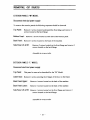
REMOVAL OF PARTS
OUTER DOOR PANEL
SECTION 1.
Disconnect electrical power supply
Open the door to the horizontal position
and remove the three PhiIlips head stainless
steel screws fitted to each side of the door
to enable the Outer Door Panel to be
withdrawn from the stainless steel door liner.
Whilst removing the six stainless steel screws,
ensure the Outer Door Panel is supported to
prevent damage. It is suggested to leave one
central screw loose and in place for support
whilst removing the three stainless steel screws
on the other side of the door.
To remove the Outer Door Panel, support the
side with all three screws removed with your knee
under the Outer Door Panel while holding the Outer
Door Panel and stainless steel door liner together
on the opposite side with your free hand and remove
the remaining central screw.
Carefully lift the Outer Door Panel clear, carry out
any work required. Re-fit the Outer Door Panel.
- 23
REMOVAL OF PARTS
SECTION 2
DETERGENT DISPENSER
Disconnect electrical power supply
Remove the Outer Door Panel.
Remove the six retaining screws which fix the
Detergent & Rinse Aid Dispenser to stainless
steel door liner through upper and lower fixing \~~4~~~~~
brackets. On electronic models, attached to the
LiiliilliililU
right hand corner ofthe upper fixing bracket by
one ofthe retaining screws, is the Thermistor
Retaining Clip.
Remove the Detergent & Rinse Aid Dispenser
from the stainless steel door liner.
Upon refitment of a Detergent & Rinse Aid
Dispenser to the stainless steel door liner ensure
the sealing face area is clean and free from
damage. To ensure an effective seal between the
Dispenser seal and the stainless steel door liner
face, alternatively tension the two centre screws
through the upper and lower brackets and then
the upper and lower corner screws.
Operate & test machine before leaving.
Note: The Dispenser upper & lower fixing bracket also clamp the thermistor bracket,
insert thermistor in bracket before tightening screws. Refit Outer Door Panel.
- 24
REMOVAL OF PARTS
CONTROL PANEL
SECTION 3
Disconnect electrical power supply
Remove the Outer Door Panel
(Section 1)
Remove the Six Phillips Head countersunk
stainless steel screws located at the top
section ofthe stainless steel door liner.
Four screws are located on the top ofthe
liner flange and a screw on each side is 80mm
from the top corner.
Close door, pull control panel assembly forward
Cany out work required. If the Control Panel is unserviceable remove the components
and assemble them onto a new Control Panel.
Before reassembly on to the top ofthe door ensure that the reinforcing channel is in its
correct position, otherwise it could be very difficult to reopen the door.
Refit Control Panel. Ensure door handle operates correctly and locking hook latches
securely.
Refit Outer Door Panel.
- 25
REMOVAL OF PARTS
MEMBRANE SWITCH
SECTION 4
Replacement of Membrane Switch
Remove Outer Door Panel and Control Panel. Section 1 & 3.
Removal of the membrane switch can be done without removing the power/control
board. Remove the membrane switch tail from the board connector by unlatching the
patent tail connector. (See sketch.) Remove the touch-control as follows. Insert the
blade of a knife or small screwdriver under the extreme left hand corner ofthe
membrane assembly and prise it from the Control Panel. When sufficiently removed to
grip with tweezers or fingernails gently pull the adhesive backed assembly off the panel
for the full width of the membrane. Grip the extreme end and remove.
-------
Finger Grip
F ilrn Swi tch
~
Slide top
part to
unlatch.
Replacing the Membrane Switch
Clean the switch area of the Control Panel front with a clean cloth using methylated
spirit. Any gum adhering to the board will not be dissolved by methylated spirit, but it
can be rolled up into itselflike dough and it departs cleanly from the Control Panel.
Starting at the left hand end of the membrane switch facing the front ofthe panel,
lightly align the membrane assembly at the left end, butting it against the plastic
moulding of the handle opening. Lay the ribbon/membrane assembly down when half
way along, feed the tail through the slot in RHS end. After checking for correct
positioning gently press the assembly down to adhere firmly.
- 26
REMOVAL OF PARTS
SECTION 5
CONTROL BOARD
Replacement of Power Control Board
Remove Outer Door Panel and Control Panel Section 1 &3.
Removal
Disconnect the film switch from the connector. (See sketch)
Remove 3 circuit board mount screws.
Lift PCB and place in front of control panel.
Remove dew protection and carefully disengage the LED sub-board which is
connected to the peB.
Replacing the P.C. Board
Placing the Control Panel upside down on a bench, place the board and LED
sub-board cOIUlected to it, near the switch end. Carefully insert the LED board into
position while holding the plastic clips up alternately with a thumb. ENSURE THE
LED'S AREN'T DAMAGED WHEN SLIDING THE BOARD INTO POSITION.
The LED'S should now be in the centre of the control board holes provided for them.
Place the main board in position and secure with the 3 screws.
Door Switch
Terminal~"""""':
2 1eads
LED Ci rcuit
Board Mount
Clips. (2 clips)
Ribbon Cable
/
LED Bezels
Lift Clip
l}?t:
LED Bezel
Panel
- 27
REMOVAL OF PARTS
DOOR SAFETY SWITCH
SECTION 6
Replacing the Door Safety Switch
Remove Outer Door Panel and Control Panel. (Section 1 & 3)
Remove clip retaining microswitch assembly (See sketch), and pivot the assembly to
clear the retaining lug of the black plastic moulding.
Withdraw the switch from the mounting spigot by pulling forward.
Remove the rubber cover and pull quick-connects off switch terminals.
Assemble in reverse order.
".---.......-\..
--'..
Micro Switch
Leads \
Micro Switch
Mount Spigot
Micro Switch
Contact Point
Micro Switch
(to remove
pull switch out)
Micro Switch Cover
(to remove or
replace, angle the
assembly and remove
Micro
Mount
from spigot).
- 28
REMOVAL OF PARTS
EXTERIOR PANELS "M" MODEL
Disconnect electrical power supply
To remove the exterior panels the following sequence should be observed.
Top Panel:
Remove 2 screws located underneath the front ledge and remove 2
screws located at the back flange.
Bottom Panel: Remove 2 screws located on each side of the bottom panel.
Back Panel: Remove 6 screws located on the back of the machine.
Side Panel LH & RH:
Remove 2 screws located on the front flange and remove 2
screws located on the back flange.
Assemble in reverse order.
EXTERIOR PANELS "L" MODEL
Disconnect electrical power supply
Top Panel:
This panel is removed as described for the <CM" Model.
Lower Door: Remove 4 screws securing the 2 hinges ofthe door to the frame.
Back Panel Upper:
Remove 6 screws located on the back ofthe machine.
Back Panel Lower:
Remove 4 screws located on the back ofthe machine.
Side Panel LH & RH: Remove 3 screws located on the front flange and remove 2
screws located on the back flange.
Assemble in reverse order.
- 29
REMOVAL OF PARTS
Stainless Steel Door Liner
The stainles steel Door Liner is retained to the machine hinges located at the base of
the stainless steel Tub. Two stainless steel Phillips head countersunk screws on each
side of the lower section of the stainless steel Door Liner Flange, clamp the Door Liner
to the Swing Arm (movable arm) of the hinges.
The Fixed Arms ofthe hinge assembly are screwed to the front flange of stainless steel
Tub by two stainless steel countersunk Phillips head screws, identical to the screws
used on the Swing Arms of the Hinges. It is advised to remove both Push Rod Springs
prior to removal ofthe stainless steel Door Liner from the dishwasher.
Disconnect electrical power
Remove Outer Door Panel
Remove the Door Hinge Springs and Push
Rod Guides
Remove the four stainless steel Phillips head
countersunk screws from the side flanges
with the door in the open position, as shown
right.
Return the door to a partially closed position
as shown in the photograph below right to
prevent damage to the spillway fixed to the
front lip of the stainless steel tub.
With the Swing Arms ofthe door hinges
returned to the door open position, lift the
stainless steel door liner clear of the
machine as shown below right.
Reassemble the machine in reverse order.
Move Door
Liner to near
closed position.
-...
- 30
.').
REMOVAL OF PARTS
DOOR HINGE, SPRING & PUSH ROD GUIDES
Disconnect electrical power supply.
Remove Top and Side panels to expose the door
hinge system. The complete door assembly is
counter balanced with a compression spring
system mounted at each side of the machine.
A Push Rod is connected to the Swing Arm
of the hinge plate forming a lower pivot point.
The upper end of the Push Rod is supported
by the Fixed Guide which is anchored to
the chassis rail by two retainer clips.
Upon opening the door the Push Rod will
pass through the bore of the Fixed Guide,
decreasing the length of the Push Rod
between the step and Fixed Guide.
Hence the compression spring located on
the Push Rod will be compressed by the
reduction oflength between the step
ofthe Push Rod and the Fixed Guide.
Closing the door will result in an increase oflength
between the step of the push rod and the fixed guide,
resulting in a reduction of the spring tension.
To remove the Push Rod and Fixed Guide, close the door and
push the Fixed Guide downwards to unlatch the two retainer
lug clips, whilst pulling the bottom of the Fixed Guide away
from the Chassis Rail.
Upon removing the Fixed Guide from the Chassis Rail slots,
tpe Push Rod and Door Spring can be disconnected from the
Swing Arm of the Hinge Plate by tilting the Push Rod
outwards to disengage the offset keeper/retainer.
Reassemble in reverse order.
- 31
REMOVAL OF PARTS
DOOR HINGES
Disconnect electrical power supply
The Door Hinges consist of a left hand and right hand hinge assembly. The fixed arm is
mounted to the flange ofthe stainless steel tub by two stainless steel countersunk screws,
whilst the swing arm or movable arm is attached to the stainless steel door liner flange with
two stainless steel countersunk screws. A positive stop position is provided with the door
in the open position by the swing arm locating on a heavy projection formed on the fixed
arm of the hinge.
To replace the Door Hinges, the stainless steel door liner needs to be removed.
Remove the two stainless steel screws which clamp the fixed arm to the flange of the
stainless steel tub.
Repeat procedure for the opposite side.
Replacement hinges can be fitted by reversing the procedure.
Reassemble in reverse order.
Operate & Test machine before leaving.
Hinge Fixed Arm
Hinge Swing Arm
- 32
REMOVAL OF PARTS
Upper Basket Rail &Wheel Guides
On each side wall surface of the stainless steel tub is
mounted a heavy gauge stainless steel Rail Guide, which
is free to slide forwards and backwards, when the top basket
is pulled out to load/unload. The two Rail Guides support the
top basket by means of a set ofwheels attached to the top basket,
which engage the top and lower surfaces of the Rail Guide.
Each Rail Guide is supported by two Wheel Guides located on
each side of the stainless steel tub wall surfaces, which support
and allows each Rail Guide to slide freely.
Each Wheel Guide has a stainless steel axle which is threaded
into a heavy gauge support plate, affixed to the external surface
of the stainless steel tub, by a stainless steel Phillips head screw
clamped to each vertical chassis rail with a MS nyloc nut.
Each stainless steel Phillips headed axle is located within the
two vertical side recesses of the stainless steel tub, which
spans the complete height of the stainless steel tub walls.
As the support plate is attached to the vertical chassis rail it
remains captive even if both Wheel Guide Axles are removed
together. Previous model machines required only one Wheel
Guide to be removed at a time, as the support plate was only
supported by the two Wheel Guides.
To remove the Rail and Wheel Guides proceed
as follows:
Remove both front Rail Guide Pegs by
compressing the top sections together and lifting
clear from the Rail Guides as above right.
Slide the top basket out and clear of the Rail Guides
Remove both Rear Rail Guide Pegs from the Rail
Guides and lift clear.
Slide the Rail Guides out and clear from the
Wheel Guides.
Remove the Wheel Guide Axles by releasing
and unscrewing with a Phillips screwdriver
as shown above right.
Ensure the stainless steel cup washer, which
houses the rubber "0" ring, is identified with
the recess side of the washer to the surface
of the stainless steel tub.
Wheel Guide
Axle
~
Wheel Guide
Refer to illustration right for the correct
assembly ofthe Wheel Guide Axle. Wheel
Guide, stainless steel cup washer and rubber
~~
Reassemble in reverse order.
Peg
R
"g_JL~~~J~~~:~;;;iJlI8
p
Operate & test machine before leaving.
- 33
REMOVAL OF PARTS
Tub Gasket
The tub gasket is of a new design wherein the left hand and
right hand gasket extensions (as used in previous models) is
now attached to the tub gasket.
To remove the tub gasket, grasp the bottom
section and pull the tub gasket from the recess
formed in the stainless steel tub as shown right.
When refitting tub gasket to the stainless steel tub
recess, begin by positioning both ends of the tub
gasket into the bottom of the stainless steel tub
recess which is formed around the tub by a
flange located 8 mm from sides and top of tub.
The tub gasket has a moulded section on each
end in the form of a lip, which locates under the
irmer side of the stainless steel tub recess flange.
Ensure the lip is correctly fitted to the recess on
each end of the tub gasket.
With both ends of the tub gasket positively
positioned in the recess, press down onto the block moulded section of the tub gasket at
one end to maintain its position and commence to feed the tub gasket into the recess.
The tub gasket has three barbs moulded into the side face of the gasket and extends the full
length of the tub gasket. As the tub gasket is pushed into the recess the barbed side face
of the tub gasket engages with the side face of the recess flange.
The tub gasket is located within the recess by finger pressure only, do not push the gasket
"upwards" as this will tend to stretch the tub gasket and cause an excess in length to
occur, resulting in the tub gasket not seating correctly.
After approximately 300mm of the tub gasket has been seated into the recess, switch to
the opposite side of the machine,
press down onto the block moulded
section ofthe tub gasket to maintain its
position at the bottom of the tub and feed
the tub gasket into the recess by finger
pressure.
After seating approximately 300mm oftub
gasket into the recess, switch to other side
of machine and repeat the procedure.
Alternate procedure
Seat 300 mm of Tub Gasket at a
until both sides of
time, switching from side to side.---1~
the tub gasket has been inserted and seated correctly.
Starting at each top corner seat the gasket into the
radius ofthe stainless steel tub, alternated from side to
side ensuring it is seatedllocated correctly.
Finally, seat the tub gasket working from each side
across the top section of stainless steel tub, with
central section also to be located into recess correctly
without an excess in length oftub gasket present.
Operate & Test machine before leaving.
- 34
REMOVAL OF PARTS
Pressure Switch & Adjustment for Waterlevel
The Pressure Switch is located on the right hand front chassis
rail, directly to the rear ofthe electrical access panel, as shown
right. To remove the pressure switch proceed as follows:
Disconnect Electrical Power Supply
Remove appropriate panels.
Locate the pressure switch square detent spring
mounting on the bracket attached to the front
chassis rail as shown below right.
Compress the detent spring mounting with a pair
of pointed nose pliers as shown below, push the
mounting through the square hole in the bracket to
release the Pressure Switch.
Compress the double coil hose clamp located on
the pressure switch hose with pliers and slide hose
clamp off the pressure switch spigot.
Grasp the Pressure Switch and pull the hose from
the Pressure Switch.
Remove the 6.3mm terminals and wires from the
pressure switch tab connections.
Replace pressure switch iffaulty.
Adjust Pressure Switch for Waterlevel
To adjust Pressure Switch for Waterlevel proceed
as follows:
On the back of the pressure switch is a central spigot which.house the adjustment screw for
waterlevel.
Turning this screw clockwise raises the level and anti-clockwise lowers the level.
It is recommended, to make the adjustment, turning the screw no more than one half turn at the
one time and then check the result.
Reassemble in reverse order.
Operate & Test machine before leaving.
Compress
Detent.
- 35
-=~
REMOVAL OF PARTS
Sump
The Sump is located under the stainless steel tub and is attached to the tub by a Sump
Gasket and a Sump Retainer fitted to the interior of the stainless steel tub. The Sump
Retainer locates into the recessed aperture in the base ofthe stainless steel tub and into the
internal face of the Sump. The Sump, Sump Retainer and the recessed aperture (190mm
diameter) have an 80mm long flat section towards the front of the machine and is parallel
with the front lip ofthe stainless steel tub.
On the flange formed on the recessed aperture in the stainless steel tub is mounted a
grooved sump gasket, which is compressed between the sump flange and the sump retainer
by four mounting screws.
Disconnect electrical power supply
Remove appropriate panels.
To remove the Sump, disconnect hoses attached
to the Sump Spigots.
Remove Phillips head screw which retains the
Drain Pump to the sump socket.
Remove the four mounting screws and lift the
Sump Retainer clear as shown right.
Remove Sump from the stainless steel tub
and lift it clear from the stainless steel tub
as shown below left.
Remove the Sump Gasket from the flange
ofthe stainless steel tub as shown below
right.
Reassemble the machine in reverse order.
Operate & test machine before leaving.
- 36
Remove Sump Retainer.
REMOVAL OF PARTS
Wash Motor/Pump Assembly - Removal and Refitting
The Wash Motor/Pump Assembly is a high efficiency compact devise horizontally
mounted at a 30 0 angle to the rear rail and located within the rear left hand corner of the
machine as shown right. A centrally positioned induction or inlet spigot on the pump
cover also provides the front mounting via a short hose connected to the sump ~pigot with
appropriate hose clamps.
. - .
To remove the Wash MotorlPump Assembly
from the machine proceed as follows:
Disconnect electrical power
Remove appropriate panels.
Disconnect the four pin wash motor/pump
receptacle from wiring harness/plug as shown
above right.
Remove the two pump outlet hoses from the
pump cover by compressing the double coil hose
clamps and sliding the clamps and sliding the clamps
along the hoses away from the pump cover spigots.
Short hose connection
Disconnect
The two hoses as shown above right are
between pump inlet
four pin
receptacle.
identified as follows:
spigot and sump spigot.
• Upper hose - 22mm diameter pump spigot parallel with the base of the stainless steel
tub. Function:- Water supply to Top Spray Arm.
• Lower Hose - 25mm diameter pump cover spigot - hose connector. Function:- Water
supply to Lower Spray Arm.
Move double coil hose clamp
Grasp each hose in turn and disconnect
away from Wash Pump/Motor.
from the pump cover spigots.
Removal of the two outlet hoses now
provides access to the centrally mounted
induction/inlet spigot of the pump cover.
Compress the double coil hose clamp
located on the inlet hose and slide clamp from
spigot towards the Sump as shown left.
Note: The Wash Motor/Pump is actually
supported by the short hose between the
Wash Motor/Pump and the corresponding
spigot of the Sump.
- 37
REMOVAL OF PARTS
Wash Motor/Pump Assembly - Removal and Refitting (Cont'd)
The rear end of the Wash Motor is supported by a triangular detachable neoprene
Mounting Support Strap, which is attached to a hook located on the left hand rear chassis
panel. On the rear diecast end-shield ofthe Wash Motor are the support hooks onto
which the two lower holes ofthe triangular Mounting Support Strap are attached to
support the Wash Motor. Refer to the previous photo which has the rubber triangular
Mounting Support Strap removed to clearly show the hooks.
Two options are available to remove the Wash Motor triangular neoprene Mounting
Support Strap:
Twist the Mounting Support Strap and push the
locating hole from the front hook on the Wash
Motor end-shield as shown right. Push the
Mounting Support Strap up and release the
Mounting Support Strap from the hook
located on the chassis panel. The rear
locating hole ofthe mounting support strap
can then be disengaged from the hook on the
wash motor end-shield. The wash motor
mounting support strap can then be lifted clear
ofthe machine.
OR
Remove the retaining screw which mounts the
hook onto the chassis panel. Detach both
locating holes in the Mounting Support Strap from both hooks on the Wash Motor
end-shield. Lift clear the Mounting Support Strap and the detached chassis hook from the
appliance.
The Wash Motor/Pump can then
be withdrawn from the pump
cover inlet hose, as shown
below right, and lifted clear as a
complete assembly.
Refit the Wash MotorlPump and
reassemble the machine in
reverse order or refer to section
Wash MotorlPump requires to be
dismantled.
Operate & Test machine before
leaving.
REMOVAL OF PARTS
Wash Motor/Pump - Dismantle
Sit the Wash Motor/Pump upon the rear diecast end-shield on a table or suitable flat
surface. Whilst viewing the Wash MotorlPump assembly from the pump cover end,
position the two support hooks formed on the diecast end shield at a twelve 0' clock
position. It should be noted the pump outlet spigot for the water supply to the Upper
Spray Ann is at the nine o'clock position, whilst the pump outlet spigot for the lower
spray arm is at the four o'clock position. The alignment of the pump cover to the two
support hooks on the diecast end-shield ofthe motor must be maintained for correct
fitment of the Wash MotorlPump to the machine.
Directly below the pump outlet spigot located at the four 0' clock position (Lower Spray
Ann water supply) on the outer diameter, is a 3 mm diameter round spigot, engaged into a
slot on a corresponding black plastic flange, which is known as the Pump Plate.
Locate the small locating spigot and corresponding cutout (3mm wide) and mark this
location onto the diecast flanged end-shield of the Wash Motor (four o'clock position)
with a felt tipped marking pen for re-assembly purposes. It can also be noted that the four
0' clock position is identified by the electrical input cables entering the stator at this
.
. position.
Release and remove the four Phillips head screws which retain the pump cover to the
Pump Plate and wash motor flanged diecast end-shield.
Lift clear the pump cover and the neoprene "0" ring which seals the pump cover to the
pump plate.
The pump impellor requires to be removed to access the removal of the Pump Plate.
To remove the impellor from the shaft, insert a screw driver into the opposite end diecast
end-shield air cooling vents and engage with a blade of the cooling fan (eight diecast
blades on rotor), to lock the rotor in a stationary position. Whilst holding the screw driver
firmly, grasp the impellor and turn in an anti-clockwise direction to unscrew the impellor
from the shaft. Lift impellor clear from the pump shaft.
The flanged pump plate which houses the carbon faced rotary seal and bellows can also be
lifted clear from the Wash Motor.
Upon lifting the Pump Plate clear, the flanged diecast end-shield of the Wash Motor will
be visible. A black plastic water slinger is attached to the motor shaft, which is housed by
an annular projection with a cutout at the six o'clock position, to allow water leaking past
the rotary seal to exit the flanged diecast end-shield.
Refer to re-assembly section of Wash Pump.
_c·_
Screwdriver inserted into cooling
vents/blades to lock shaft.
- 39
REMOVAL OF PARTS
Wash Motor/Pump - Reassemble
Position the Wash Motor with the two mounting hooks at the twelve o'clock position and
the input electrical cables in a corresponding four 0' clock position. Ensure the motor is
electrically sound and the bearings are not water damaged/noisy.
The Pump Plate is normally supplied as a replacement with the bellows and carbon faced
seal factory fitted. On the underface ofthe Pump Plate are two cutouts, within the outer
mounting rings, positioned on each side of a mounting hole.
Note: Both cutouts are to provide an exit for water leakage past the rotary seal and
impellor ceramic face. This mounting hole must be positioned directly opposite the two
mounting hooks at the twelve o'clock position. ie: Positiop the mounting hole and two
cutouts at six o'clock position on the flanged diecast end-shield ofthe Wash Motor.
Note that the large directional vane for the lower spray arm spigot is then located at the
four o'clock position.
Check the condition ofthe pump impellor for damage and inspect the ceramic rotary seal
face for condition/damage. If damage/wear is present replace both impellor and pump
coverlrotary seal.
Fit the impellor to the right handed threaded pump shaft. Rotate impellor and compress
rotary bellows/seal until the rotor ofthe Wash Motor commences to rotate withthe
impellor.
Insert a screw driver into the opposite end diecast end-shield air cooling vent and lock the
blades of the cooling fan and rotor from turning, whilst screwing the impellor onto the
shaft at the opposite side ofthe wash motor/pump. Tighten impellor securely and remove
screw driver from the blades ofthe cooling fan.
Clean and refit neoprene "0" ring to Pump Plate if a replacement is not available. It is
suggested to fit a replacement if a pump is serviced.
Refit the pump cover to the Pump Plate ensuring the 3mm spigot on the pump cover
locates into the cutout (3mm) ofthe Pump Plate located at the four o'clock position.
Refit the four Phillips headed screws to the pump cover pump plate wash motor mounting
holes. Tighten all four screws evenly, alternate from side to opposite side to ensure the
pump cover and pump plate compresses the neoprene "0" ring correctly.
Insert a finger in to the pump cover inlet spigot, engage with the impellor blades and
establish the impellor/wash motor rotor is free and turns without fouling the pump cover.
Refer to removal and refitting section of Wash Motor/Pump.
Ceramic Face
of Impellor
- 40
--~ .....
REMOVAL OF PARTS
DRAIN PUMP - REMOVAL
The Drain Pump is a self contained motor and pump assembly mounted directly into the
Sump by the induction or inlet spigot equipped with an neoprene ''0'' ring to prevent
water leakage. A single Phillips head screw retains the complete motor and pump to the
Sump. Removal of the Drain Pump is accomplished by the following procedure:
Disconnect electrical power supply
Remove appropriate panels.
Disconnect the two QC terminals and wires from the 6.3mm tabs marked "L&N' mounted
on the encapsulated field windings of the Drain Pump Motor.
Remove the drain hose double coil hose clamp with a pair of multigripsJpliers from the
pump outlet spigot as shown below left and withdraw the moulded drain hose elbow from
the pump outlet spigot. The moulded elbow of the Drain Hose has two offset slots in the
end face of the elbow, which engage with the offset lugs on the pump cover/outlet spigot.
This feature is to index the drain elbow/hose into the correct angle and position in relation
to other internal components.
Remove single Phillips head screw which retains Drain Pump to the sump socket as shown
below right
~.~...,-~
.. ~i~1
._~~
Grasp the Drain Pump and pull the complete motor and pump assembly from the bore of
the sump socket, wherein the Drain Pump Spigot and neoprene "0" ring is housed as
shown below.
The Neoprene "0" ring is removed from the
pump cover/inlet spigot and discarded. A
replacement neoprene "0" ring should be
used upon refitment of the drain pump.
Refer to refit section of the Drain Pump or
refer to dismantle section of the Drain Pump.
- 41
REMOVAL OF PARTS
Drain Pump - Dismantle & Assemble
As the Drain Pump is a self-clearing devise, generally, the Drain Pump will not require to
be dismantled. However, if there is a need to dismantle the Drain Pump after having
removed it then follow this procedure:
Removal of the Drain Pump cover/inlet spigot will require a ''Torx'' hand driver fitted with
a T-15 drive to remove three torx headed screws which retain the pump cover/inlet spigot
to the pump body/motor assembly. Prior to removing the three torx screws, view the
Drain Pump from the motor end with the two electrical tap terminals marked from left to
right as <eN' & ''L'' and also inverted. The pump cover outlet spigot (three deep grooves
on surface) is positioned in relation to the electrical terminals '"N" & ''L'' at an eleven
o'clock position. Mark both pump cover and pump body to retain this relationship.
Remove the three torx headed screws and separate the pump cover from the pump body.
A Neoprene "0" ring is located within a groove on the pump housing, carefully remov~
the "0" ring, clean the groove and refit the "0" ring.
A flap valve is incorporated within the pump cover/inlet spigot. The purpose ofthe flap
valve is to ensure water from the household drain system will not flow back into the
dishwasher. Located within the end groove on the pump cover/outlet spigot is the
retaining ring/flap valve. Lift the retaining ring/flap valve from the groove, clean, examine
for damage and refit to pump cover/outlet spigot groove.
Establish that the domed surface of the flap valve is towards the seat face of the pump
cover/outlet spigot. The retaining ring of the flap valve should be positioned within the
groove, for the domed surface of the flap valve to contact the seat face effectively and be
concentric with the bore of the pump cover/outlet spigot.
NOTE: If the flap valve is not seated correctly it will not operate as a non-return valve.
Refit the pump cover to the pump body, locating the outlet spigot at the eleven o'clock
position in relation to the electrical terminals ''N & L". Press both components together
without damaging the neoprene "0" ring and fit the three torx head screws and tighten
evenly.
Insert finger into pump coverrmlet spigot, engage with the impellor blade and establish
impellor will turn freely.
NOTE: A magnetic effect between rotor and stator will cause the impellor to ''flick''
past the poles of the motor every 180 0 of rotation. This is normal and the effect is used to
obtain a self clearing pump action.
Refer to refit section ofthe Drain Pump.
- 42
REMOVAL OF PARTS
DRAIN PUMP - REFIT TO MACHINE
Disconnect electrical power supply
It is recommended to replace the neoprene «0" ring which seals the pump coverfmlet
spigot to the sump socket. Fit neoprene, ''0'' ring onto pump coverrmlet spigot and locate
against the eight stops moulded onto the surface ofthe inlet spigot.
When engaging the drain pump inlet spigot to the sump socket, it is advised to smear
water onto the surface ofthe neoprene ''0'' ring, to assist entry into the sump socket.
Approximately position the pump cover/outlet spigot towards the front ofthe machine, or
in a horizontal mode, insert the pump cover/inlet spigot into the sump socket.
Exert hand pressure against the drain pump to compress the neoprene «0" ring and rotate
at the same time approximately 90°, to seat the slotted locking plate ofthe Drain Pump
against the retaining boss of the Sump.
Refit the Phillips flange head (two start thread) screw. Do not over-tighten.
Slide the double coil hose clamp over the drain hose elbow and fit the elbow over the
pump cover/outlet spigot. Engage the two offset slots in the end of the drain hose elbow
with the two lugs on the pump cover/outlet spigot.
Push the drain hose elbow finnly onto the two offset slots and lugs.
Compress the double coil hose clamp with multigrips/pliers and position clamp on drain
hose elbow between the wash motor/pump and Drain Pump. This position allows access
to refit or remove the double coil hose clamp with multigrips/pliers.
Refit the QC Terminals and wires to the Drain Pump tabs marked «N" & '1..,".
Reassemble in reverse order.
Operate & test machine before leaving.
- 43
54hiJ
322A
5236
326
505
130A
~330
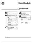
Page 4 DW177
~330A
~322B
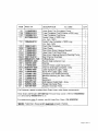
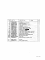
ITEM
PART N°
DESCRIPTION
130A
150
260
301
308
322
322A
322B
326
1524445-01/0
Sea~Sleeve Oute~
Ex. 5982
SK
WK
1
1
N.P.A.
NO PART AVAILABLE
0
0
----------- -
r-- 1526645-12/0
2
2
Spring Hinge _________________ r----
r-----,--
1526298-04/5
Bottom Cabinet
1
1
-"-
r----------
50286354-00/1
Kit Door HJr"lge Right/Left
2 1 - - 2- - -
-----
1
1527129-61/1
1
Crossbar Front Upper
_._-
----
1
1526299-02/7 1
Crossbar Back UPp~___. - - - - - t-------
1527256-10/9 - Crossbar Front
Bottom
1
1 -
-------- - - -
t------- r---
1
1170380-60/2
Side Panel Left
------
------
1170153-4113
1
Side Panel Left
- - - - - - - - - r - - - - r--------
1
1170380-70/1
Side Panel Right
1170153-51/2
1
Side Panel Righ_t_________ ~___
- 1-----
1 -- t-------
1
1520664-01/0
Adjustable Foot
Adjustab~
Foot
Front
10mm
____
2
2
f--1527992-11/7
---
1
1 --
1522344-05/8
Latch
0- - N.P.A.
NO PART AVAILABLE___~__
~1
1
1526576-00/2
Hole Cover Latch
----
1
1
50282756-00/1
r-'!Yheel
Support
Kit
Dark
Grey
(4
PiecesL
-
4
4
1521220-03/6
Stiffenir}g13racket
-----1-
1
1 1526417-00/9
Hose Clamp
-----
1
1
1522345-03/0
Wiring fJrotection
r----- - -
----------
2
2 1520512-05/2
~il
Bas~t
Upper
-
1
1- -
1523236-03/0
Plaqu~
2
2
1520479-20/3
Stopper Front - Dark Grey
. _ - - ------ f - - - - - - -
2
8996461234-05/7
Stopper Back - Dark Grey
2
1?30mm
r------'-------~--.---
--~
--
---~-
r--------~--
-
_.~-_
..
-.~--
-~--
---_._-~-_.-
--
326A
~
~-
.---
~-
~--
-------~_._._-
---
N.I.
.----
-
_
.
r-----~
_
f----~
~
330
330A
344
I--
505
52'ID
523
5238
541
550B
552
56?
59?
59?A
50282092-00/1
Fixing Clip Stud (4 Pieces)
-
--- ---- --
4
4
Page 5 DW177
}130A:I
1451:
I
bA
o
135A
~}111
130F
a--
15j
112l
~110A
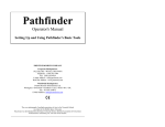
Page 8 DW177
ITEM
110
110A
-
110C
111
PART N°
DESCRIPTION
Ex. 5985
OTY
1118455-00/3
1526815-10/3
1525986-10/3
50278866-00/4
Hose Drain Tub Circulation Pump
1
--f--.
Tube Container Cup Fill Valve x 525 Long
1
Tube Container Cup Sum~
1
Feeder Hose x 1500 Long
1
(Inc. Item 130F)
1
1526492-01/0
Outlet Tube Complete x 1930 Long
(Inc. Item 520)
.
-
1
1526612-02/1
. ~n Fili~r Complete
--- - - -
1119082-00/4
1
Filter Plastic
---_.
1118945-00/3
Pipe Union Sump Heating Element
1
- --
1
1118568-00/3
Hose Drain Tub Drain Pump
f-._-_.
Pipe Union Heating Element Washing Pump -
1118946-00/1
1
1523119-01/2
1.
Seal Channel Drainage
8996461217-70/6
1
O-Ring Sump
50659231-00/0
1
Round Seal Container Cup
1
1240151-00/9
f-Sealing.
-----
1118940-00/4
1
Column Holder Lower Spray Arm
50281041-00/9
1
Channel Drainage Complete - Grey_
1118952-00/9
Lower Spray Arm LiQht - Grey
1.
-_._.. _
1118949-00/5
Spray Arm Upper LiQht - Grey
1
- --_... 1170481-10/3 - - Container Cup Small Electronic
1
1118960-00/2
1
...Manif~
Vertic'!lJ!Qc.
Item
1
~O~
-
1118955-01/0
1
Sump_ .
1170159-11/3
1
Basement
_.._ - - _.... _ - -
--
1526272-10/7
1
Grill Vapour Outlet Dark - Gr~y
1526862-00/6
1
FlanQe Discharge Pipe
1
1527389-00/9
Stopper Drainage Hose
.~
112
120
120B
127
127A
127B
130A
1308
130C
130F
132
135A
139
139A
140
145
155
303
320
520
521
---
.0.
..
-
-
..-
---
If a Customer needs to extend their Drain Hose, order these components:
Hose Drain (2M length) 0571400142, Ferrule Hose Joiner (19mm) 0182200002
(x1) and Clamp 0005001019 (x 2)
For extensions under 2 metres, use Kit Hose Flex. Drain (1 M) ES5323K
*NOTE: Total Drain Hose length must not exceed 4 metres.
Page 9 DW177
118
11B~
cC:lt
~
L10
550c
@
11~
'\
)
130
1
@ 148
fliY
Page 10 DW177
567~~
6A
ITEM
PART N°
DESCRIPTION
5
6
6A
10
11
11 B
12
12A
14
48
110C
110D
118
130
523B
550C
567
1526439-06/0
1111469-31/6
50287471-00/2
50280071-00/7
1526356-11/6
1526204-02/7
1526370-02/6
1526370-14/1
1560116-20/2
1115912-06/3
1170450-40/5
1170450-50/4
50285882-00/2
1118535-03/6
1170351-00/9
8996461234-30/5
1118709-01/1
Fill Valve
1
Washina Motor 2800 RPM
1
~rainPump 50Hz
1
1
Heater 230V/2000W 032mm.
Capacitor
1
Interference Capacitor
1
Pressure Switch Level 65/45
1
--f----
1
Pressure S~3/98
Assembly PCB
1
--
Temperature Sensor
1
---
1
Tube Pressure Switch Safety x 525 lon~___
Tube Pressure Switch Level x 525 long
I-L
1
Kit Dispenser DeterQent
----- - - - -
1
Sealinq Sleeve Temperature Sensor
1
Mount Pressure Switch
1
Cover Cap
--._
1
Rubber Da~r Circulation Pump
1 -
Harness
1
1
Power Cable AUS/NZ
"---
------~-
-----
---
----
1560119-10/7
1526453-31/9
--
~
.
~
_
___
.
L-~~
----
N.!.
N.!.
aTY
_
-~
Ex. 5998
- -
Page 11 DW177
Whiteley Industries Ply. Ltd.
A.C.N. 000906678
(Inc. in N.SW)
TECHNICAL BULLETIN
MEDICAL PRODUCTS DIVISION
SONEX
HOSPITAL AND LABORATORY EQUIPMENT DETERGENT
SQNEX is a highly active liquid detergent free of colour and odour. It is specifically designed for manual and
macbine cleanmg of anaesthetic equipment, instnunents, plastic and glass utensils in hospitals, pathology and
research laboratories.
SONEX is moderately alkaline, non flammable and completely safe for use when used in accordance with !he
directions. It is non corrosive at use dilution.
In formulating SONEX particular care was taken to ensure rapid and complete riosibility so that cleaned arti
cles are free of detergent residues. This is particularly important whenever resean:h is being conducted and
articles such as micro titre dishes must be completely detergent free after final rinsing. It is equally important
that all medical instroments be completely free of detergent residues.
DIRECTIONS FOR USE
MANUAL WASHING
Lightly soiled articles . . . . . . . . . . 5 ml per litre
Medium soiled articles . . . . . . . . . . 10 mi per litre
Heavily contaminated articles . . . . . . 15 ml per litre
The cleaning action will be accelerated if the solution can be healed.
Note: Gloves should always be worn during all manual cleaning procedures.
/
MACHINE WASHING
Lightly soiled articles
2.0 ml per litre
Medium soiled articles . . . . . . . . . . 4.0 ml per litre
Heavily contaminated articles . . . . . . 6.0 ml per litre
Where machines have automatic dispensing systems manufacturer's instructions should be followed.
CHEMICAL COMPOSITION AND PROPERTIES
Surfactant system
Colour
Odour. . . . . . . . . . . . . . . . . . ..
pH (concentrate)
,
pH (0.5% dilution) . . . . . . . . . . . ..
Foam properties . . . . . . . . . . . . .,
Anionic
Colourless
Odourless
12.5 • 12.8
9.3 • 9.6
Controlled low foam
Solubility . . . . . . . . . . . . . . . . ..
Completely soluble in water
Abrasives
Flash point . . . .
Specific Gravity .
Non Volatiles
Free Alkalinity . .
Soaps and Amines
Toxicity. . . . . .
None
None
1.060
12.9% MfV
1.5% KOH
None
Mildly toxic (alkali only)
. . . . . . . . . . .
. . . . . . . . . . .
. . . . . . . . . . .
. . . . . . . . . . .
. . . . . . . . . . .
,
.,
..
,
..
..
..
~ 0 B~~~~\~ 'N~~ ·S~~·~ ..... ,
Head Office: 18tFI
PE?'
sa
JiP111
2 years
litl~~~~)~l~o
For callers outside N.S.W. Toll Free: 1800257352
MATE~SAFETYDATASHEET
STATEMENT OF HAZARDOUS NATURE:
Hazardous according to criteria of Worksafe Australia.
R34: Causes burns
R41: Risk of serious damage to eyes.
S37/39: Wear suitable gloves and eye/face protection
S24/25: Avoid contact with skin and eyes
COMPANY DETAILS:
WBITELEY INDUSTRIES PTY. LTD. (A.C.N. 000 906 678)
Postal Address: P. O. Box 1076 North Sydney NSW 2059
Telephone Number: (02) 99299155 Facsimile: (02) 99299077
Emergency Telephone Number: Poisons Infonnation Centre (National) 13 1126
Product Name: SONEX
Intended Use: Instrument Detergent
Product Type: Alkaline detergent
Date Issued: 31't January, 2000.
Issue 5
UN Number:
Dangerous Goods Class:
Subsidiary Risk:
Hazchem Code:
Poisons Schedule:
1719
8
Nil
2R
5
PHYSICAL PROPERTIES
Specific Gravity (H20 = 1): 1.060
Solubility in Water: Soluble
Appearance Odour: Colourless liquid with no perceptible odour
Flash Point: Nil
Method: Nil
Flammability Limits: Lower: Nil
Upper: Nil
Other: pH> 13
INGREDIENTS
Chemical Family
Hazardous Ingredients
1. Alkali
2. Surfactant
Potassium Hydroxide
Sodium napthalenesulfonate
Ingredients determined
not to be hazardous
3. Nu
C4S No.
1310-58-3
68442-09-1
Proportion
2%
<10%
to 1000./0
HEALTH HAZARD INFORMATION
EFFECTS
Eye (Contact): Will cause burning pain and reddening ofthe eyes
Skin (Contact).A mild to moderate irritant. Prolonged or repeated contact may lead to dermatitis.
Inhalation(Breathing):Not volatile at normal use temperatures.
Ingestion (Swallowing): Will cause abdominal pain and nausea.
Page 1 of 2
© This document remains property of Whiteley Industries Pty Ltd
AC.N. 000 906 678
Alterations are not permitted without Company approval.
SONEX
DISCLAIMER
The user should consult the company prior to use of this MSDS to ensure this MSDS is the latest available for
the product descn"bed. The information on this MSDS was based on the best information available to the
company at the date listed The user assumes full responsibility for proper use of this MSDS.
HEALTH HAZARD INFORMATION
FIRST AID
Eye (Contact): Hold eyelids open and immediately inigate with copious quantities of water for 15
minutes. Seek urgent medical assistance.
Skin (Contact): Remove contaminated clothing. Wash thoroughly with soap and water. Obtain
medical attention if initation persists.
Inhalation(Breathing): Not volatile at room temperature.
Ingestion (Swallowing): DO NOT induce vomiting. Give a glass of water. Seek immediate medical
attention.
Advice to Doctor: Treat symptomatica1ly as for an alkaline detergent.
PRECAUTIONS FOR USE
Exposure Limits: Acute toxic data: Potassium Hydroxide (100%); Oral LDso(rat)= 365 mglKg
Note: Effects are reduced upon dilution.
Ventilation: Not normally required.
Protective Equipment
Gloves: Rubber or PVC
Eye Protection: Eye protection should be worn .
Clothing & Other Protective Equipment: As required to prevent repeated eye or skin contact.
Flammability: Nil
SAFE HANDLING INFORMATION
Storage & Transport Precautions: .Store in a cool place.
Spills & Disposal: Wash to drain with copious volume ofwater. Caution: Slippery when wet.
Fire-Explosion Hazard"
Special Fire Fighting Procedures: Nu
Hazardous Decomposition Products: Unknown.
WARNING: Corrosive
Prepared By: G. PROBERT
Position: FACTORY CHEMIST
Page 2 of2
© 1bis document remains property of Whiteley Industries Pty Ltd
AC.N. 000 906 678
Alterations are not permitted without Company approval.