1
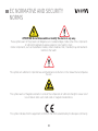
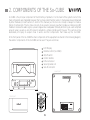
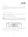
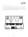
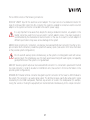
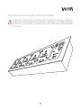
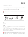
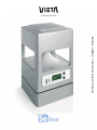
MANUAL DE INSTRUCCIONES · OWNER´S MANUAL
PROFESSIONAL SOUND SYSTEMS
www.vietapro.com
INSTRUCTIONS MANUAL
PROFESSIONAL SOUND SYSTEMS
www.vietapro.com
CONDITIONS OF GUARANTEE
SEESOUND S.L. gives you this guarantee as a purchaser of a Vieta product.
The guarantee period shall begin at the time when the final user purchases the product. Said product can
consist in different parts or accessories, which may be covered by different guarantee periods. Said periods
are as follows:
1) 24 months (2 years) for all products and accessories except those in the following section.
2) 6 months for the electric current adaptor and for the batteries included inside the module
So-1022.
This guarantee covers possible manufacturing faults for this VIETA product.
In order to be covered by this guarantee, you must go to a technical service centre authorized by SEESOUND
S.L. and present the receipt of purchase.
This guarantee DOES NOT COVER:
• Damage caused by accident, misuse or abuse.
• Damage caused by external elements or natural disasters.
• Robbery
• Damage caused by manipulation of the product by personnel not authorized by SEESOUND S.L.
• Subsequent damage to other components.
• Any costs deriving from installing or de-installing the product.
Any handling of this product by personnel not authorised by SEESOUND S.L. will automatically nullify this
warranty.
Contact your local dealer to find out which SEESOUND S.L. authorised technical assistance centre is closest
to where you live.
For more information, consult the website www.vietapro.com
02
EC NORMATIVE AND SECURITY
NORMS
ATTENTION: Do not disassemble or modify the device in any way.
These symbols warn of the presence of dangerous un-insulated voltages inside some of the components
of sufficient magnitude to expose people to risk of electric shock.
Certain components, such as the batteries module, contain materials that, if handled, may emit elements
harmful to the health.
This symbol calls attention to important use and maintenance instructions in the manual that accompanies
the unit.
This symbol warns of magnetic elements in some of the components of sufficient strength to cause risk of
loss of data in items such credit cards or magnetic medium discs.
This symbol indicates that the equipment conforms to the norms established by the European community.
03
FOR YOUR SECURITY
• Do not disassemble or modify the device or any of its accessories in any way.
• If the unit must be transported or has to remain inactive for a long period of time, remove the battery.
• It is recommended that the batteries module be stored and used in a dry place far away from sources of
heat, such as radiators, direct sunlight or the inside of vehicles. This will help to maintain the useful life of
the module and will minimize the possibility of corrosion.
• After a long period of storage, it is possible that the batteries module do not recharge completely. Charge
and discharge the batteries a few times to recover their initial capacity.
• The process of charging the module should not be performed in places where the range of temperatures
is less than 0º or greater than 40º as this could disturb the charging cycle and even cause irreparable
damage to the batteries.
• Sources of flame, such as lighted candles, such not be placed on top of the equipment. Especially, the
batteries module, as there may be vapours that react to sources of ignition.
• In case of detecting loss of liquid in the batteries module, do not use it and do not attempt to disassemble
it. This could lead to the release of materials harmful to the health and even to a high risk of fire. Get in
contact with the place of purchase of the module.
• This equipment must be handled separately to the end of its useful life as electronic waste material. (WEEE
Directive on Waste of Electrical and Electronic Equipment, 2002/96/CE)
• The equipment must not be exposed to dripping or spouting water.
• Objects filled with liquid, such as glasses, should not be placed on top of the equipment.
• This equipment is meant for use in professional sectors. Therefore, it is understood that users have a
certain technical level that will permit them to understand most of the concepts in this manual. If this is
not the case, it is recommended you contact the manufacturer or vendor for them to advise you correctly.
04
INDEX
1. DESCRIPTION OF THE EQUIPMENT
8
2. COMPONENTS OF So-CUBE
9
3. So-CUBE MENUS
14
4. FEATURES
21
5. So MODULES
23
6. CONFIGURATIONS
35
7. RECOMMENDATIONS FOR APPLICATIONS
45
8. ADDITIONAL DOCUMENTATION
46
05
DECLARATION OF CONFORMITY
SEESOUND S.L.
C/ Mar Caribe 3 • 08130 - Santa Perpètua de Mogoda (Barcelona) - SPAIN
We declare under our exclusive responsibility that the family of products:
So Line
Wireless loudspeaker, transmitting equipment and modules
Year of EC marking 2006
EMC
Is in accordance with the following directives:
89/336/CEE
Directive on Electromagnetic Compatibility
99/5/CE
Directive on Telecommunications Terminal Equipment
and is adapted to standard norms
UNE-EN 61000-6-3:2002; UNE-EN 61000-6-1:2002
Electromagnetic compatibility (CEM). Part 6: General norms. Section 1: Immunity in residential, commercial and light industrial
environments. Section 3: Output norm in residential, commercial and light industrial environments.
UNE-EN 60215:1995
Security regulations for radio-electric output equipment.
UNE-EN 55103-1:1997; UNE-EN 55103-2:1997
Electromagnetic compatibility. Regulations for the family of products for devices used in professional sound, video,
audiovisual systems and for the control of events lighting. Part 1: Emission. Part 2: Immunity.
ETSI EN 301489-1 v.1.4.1; ETSI EN 301489-9 v.1.3.1
Questions of electromagnetic compatibility and radio-electric spectrum (ERM). Norm of electromagnetic compatibility (CEM)
for radio-electric equipment and services. Part 1: Common technical requirements. Part 9: Specific conditions for wireless
microphones and for similar audio link via radio-frequency (RF) equipment.
Checked by:
Applus Corp.
Campus UAB; Post Box 18
08193 Bellaterra (Barcelona), Spain
Date: 21 June 2006
Santa Perpètua de Mogoda (Barcelona), 21 June 2006
06
ACKNOWLEDGMENTS
Thank you for acquiring the VIETA SO and showing your faith in the brand for mounting your events or
applications. It is highly recommended to read this instructions manual in order to obtain maximum performance
from the equipment.
i
User manual corresponding to software version 1.15 of the So-Cube
i
It is equally recommended that the user visit the website from time to time, as updates to this instructions manual
will appear in the future that will incorporate new accessories as well as new sections.
The user is recommended to use gloves. This will avoid the risk of being cut or harmed while handling the
equipment, as well as avoiding the possibility of leaving marks on the aluminium surface of the equipment and
its components.
07
1. DESCRIPTION OF EQUIPMENT
The product that you have just acquired forms part of the So-Line family of products. Said family is made
up of the following equipment and modules:
• So-CUBE
• So Slave One (So-1001)
• So Slave Two (So-1002)
• So Station One (So-1101)
• So Station VDC (So-1102)
• So Battery (So-1022)
• So Conex (So-1032)
• So Remote control (So-1042)
• So Stand 80 cm. (So-1052)
• So Stand 130 cm. (So-1053)
• So RF unit (So-1062)
• So Master battery charger (So-1072)
• So Flight case (So-1073)
In the following manual, it will be explained how each of the different modules works, except in the case of
the UHF SO STATION VDC (So-1102) transmitter and the wireless receiver module (So RF UNIT
(So1062) which have of a separate user manual from this one.
The So has been conceived to create complete sound systems, such as for events, speeches and conventions,
among others. The system can be defined principally as a network of omni-directional closer-range wireless
loudspeakers, comprising a transmitter, receiver and accessories for adapting to the needs of the system.
The So revolutionizes the concept of sound systems as it offers advantages such as:
• Possibility of installations with total elimination of wiring, both of audio signal and electric
network.
• Possibility of placing the wireless receivers anywhere, thereby offering
great versatility to the installer when locating sound points.
• Attractive modular design and easy set-up.
Information about the So-CUBE is to be found in the following section. To consult information on additional
modules in the SO family, go to section 5.
The instructions for setting up the unit and its accessories are found in section 6.
08
2. COMPONENTS OF THE So-CUBE
So-CUBE is the principal component of the SO family of products. It is the heart of the system in which the
main components are integrated. However, the So-Cube cannot function alone; it must always be accompanied
by other modules (consult sections 5 and 6 of this manual), as the So-Line concept is always to create a
family of components. The So-Cube consists of an acoustic receiver area that includes a professional UHF
module to receive the audio signal, a power stage and a loudspeaker (thereby functioning as a self-amplified
acoustic area), as well as an LCD screen to establish a simple interface with the user. This section will be
dedicated principally to explain how it works and the components that make up the So-CUBE.
In the front panel of the So-CUBE the main components of the equipment are found. In the following diagram,
the exterior components of the So-CUBE can be seen. They are as follows:
1
2
3
4
5
6
7
LCD Display
Remote control (So-1042)
On/off switch
Control buttons
Infra-red sensor
Security cable slot
Sub-D connector
Lower part
7
ON
4
OFF
3
1
Back part
2
MADE IN SPAIN
6
10-000100
794 ~ 806MHz
12V ~ 18V
12W
CUBE
09
Model
Watts RMS
Power
Frequency
Serial Nº
IR
5
2.1 LCD SCREEN
The So-CUBE has an LCD screen that shows information to the user. The screen has 2 lines with 8 characters
each. The information that appears on this screen can be seen in section 3, corresponding to the different
menus of device.
2.2 REMOTE CONTROL (So-1042)
Various functions of the So-CUBE can be operated via infrared remote control. The remote control sensor
is in the front panel of the equipment (see section 2.5).
These are the functions of each of the remote control buttons:
MUTE: Completely deactivate the sound of the So-CUBE, regardless of whether the audio signal comes from
the RF signal or from one of the line inputs (Mini jack or XLR, see section corresponding to module SO 1032
for more information). 2 indicators appear on the main screen to indicate that this function is activated.
ON
IR
OFF
Picture 1. Indicator that appears on screen when the So-CUBE has MUTE activated.
This function will be deactivated only when the MUTE button is pressed again.
10
CH : Direct access to the channel menu.
F1 : Key reserved for future applications.
F2 : Key reserved for future applications.
F3 : Key reserved for future applications.
F4 : Key reserved for future applications.
RF : Direct access to the RF VOL menu.
LINE : Direct access to the LINE VOL menu.
VOL + : Increase volume key. Operative in menus RF VOL and LINE VOL.
Increases the volume by one. If it is maintained pressed it continues to
increase by units until the user stops pressing the key.
VOL - : Decrease volume key. Operative in menus RF VOL and LINE VOL.
Decreases the volume by one. If it is maintained pressed it continues to decrease by units until the user stops
pressing the key.
NAVIGATION CURSORS : The navigation cursors serve to move among the different menus of the device.
The right navigation cursor is to advance and the left navigation cursor to go back and thus move among
the different So-CUBE menus.
The other 2 navigation cursors (up and down) are used to change the signal reception channel.
They are only used when the So-CUBE is on the Channel Menu screen.
OK : The OK key permits any variation made in the parameters to be memorized in the equipment (for
example, variations in volume or in channel selection). The OK key also establishes the menu screen the
equipment was at when memorization of the data occurred as predetermined.
This last requisite is very useful for the user to establish the start-up screen desired depending on the use
that is to be made of the equipment.
11
2.3 ON/OFF SWITCH
On/off switch for the equipment. Press it to start and turn off the unit. Once the on/off button is pressed
approximately 4 seconds will pass during which the equipment will remain muted until an internal relay is
activated that allows the audio signal to reach the loudspeaker.
This avoids connection sounds when connecting and disconnecting the equipment hat might damage the
loudspeaker.
2.4 CONTROL BUTTONS
Two buttons are found on the front panel of the So-CUBE. These buttons have the same function as the VOL
+ and VOL – buttons on the remote control, except in the Channel Menu, in which they have the same
function as the up and down navigation cursors. By pressing the 2 buttons together, the user will be able
to move among the different So-CUBE menus.
2.5 INFRARED SENSOR
Window situated in the front panel that permits infrared communication between the So-CUBE and the So1042 (remote control).
2.6 SECURITY CABLE SLOT
Slot to connect an optional security cable to the equipment.
The security solutions are conceived to act as preventative measures. These solutions do not mean
that the product cannot be maltreated or stolen, for which the manufacturer accepts no responsibility.
12
2.7 CONNECTOR SUB-D
The underside of the So-CUBE has a standard Sub-D 25 pin connector. This connector will permit the SoCUBE to be inter-connected with other accessories that make up the family, such as the batteries module
(SO 1022) and the connections module (SO 1032), which are also provided with a connector of the same
specifications.
Consult section 6 for more information on the different configurations of the So-CUBE and the rest of the
accessories, as well as a more exhaustive explanation of connecting between modules.
13
3. THE So-CUBE MENUS
This section gives an explanation of the different menus that appear on-screen in the So-CUBE as well as
the different adjustments that can be made in each of said menus.
To navigate around the different menu screens of the So-CUBE it is necessary to use the left and right
navigation cursors on the remote control (So-1042) or to press simultaneously both control buttons.
3.1 PRESENTATION MENU
Images 2 and 3. The So-CUBE presentation screens.
It is the first screen to appear when the equipment is turned on. It is a presentation menu that remains for
a few moments. After having presented this menu on screen the equipment will automatically pass by default
to the channel selection menu (Channel Menu) as long as the user has not previously changed this parameter.
It is possible to change the predefined screen that appears after the presentation menu. To make this change,
you must use the left and right navigation cursors to go to the menu that you wish to establish as predetermined
and press the OK button of the SO 1042.
The loudspeaker will remain disconnected while this menu is present on the screen.
i
It is necessary to bear in mind that each time a parameter of the So-CUBE is changed and you wish to store
the new configuration via the OK button, this must be done from the screen that the user wishes to establish
as predefined, in order to avoid the equipment going by error to an undesired screen after changing the system
parameters.
Garwood is a registered trade mark. Garwood is an English company that is a leader in the field of events
monitoring, specializing in wireless transmission. Garwood has collaborated closely with Vieta to develop this
product.
14
3.2 CHANNEL MENU
Image 4. Screen corresponding to the Channel Menu
Menu that shows on-screen the channel selected at any moment, through which the So-CUBE receives the
RF signal. The screen shows the numeration of the channel selected as well as its work frequency.
This menu can be accessed directly using the CH key on the remote control.
The numeration of the channels is established by hexadecimal code, meaning that the So-CUBE has 16
independent channels numbered from 0 to F. Each channel functions with a predetermined work frequency.
The work channel of the So-CUBE can be changed via the up and down navigation buttons of the remote
control or by using the buttons situated in the front panel of the So-CUBE.
Special attention should be given to channel 0. This channel has a frequency assigned by default, but if the
user selects this channel and the RF transmitter is not emitting to its frequency, the internal modulator of
the So-CUBE go into auto-frequency mode and will tune to the first frequency it finds. This will only occur
in this channel.
The work frequency band is situated between 794-806 MHz. This band can be varied by request to the
manufacturer. It is essential that this variation be requested both for the So-CUBE and the So-1101.
15
Practical examples of channel tuning
Example 1
The user selects transmission of a frequency of 800.4 MHz. In the Channel menu select channel 9 (when
working in the band between 794 and 806MHz) to receive correctly the signal emitted or select channel 0,
So-CUBE’s internal RF modulator; it will then capture the signal of said frequency as long as it does not find
an RF signal different from its work frequencies.
Example 2
The user selects to transmit to a frequency of 802.5 MHz (in the case of working in the band between 794
and 806MHz). In the Channel menu channel 1 should be selected to receive correctly the signal emitted,
or by selecting channel 0 the So-CUBE internal RF modulator will go on to capture the signal of said frequency
as long as it does not find an RF signal different from its work frequencies.
Example 3
The user selects to transmit to a frequency of 798.3 MHz (in the case of working in the band between 794
and 806MHz). Channel 0 should be selected in the Channel menu to receive the signal emitted correctly.
3.3 RF VOL MENU
Image 5. Screen corresponding to the RF VOL Menu
Menu that shows on-screen the current volume of the RF signal received by the So-CUBE.
The volume can be varied via the VOL+ and VOL – buttons of the remote control or via the buttons situated
on the front panel of the So-CUBE. This menu can be accessed directly using the RF key on the remote
control.
16
The value of RF signal volume is expressed in graduated scale, the minimum value being a line to the left
of the display and the maximum a box with an F inside situated to the right of the display.
3.4 LINE VOL MENU
Image 6. Screen corresponding to the LINE VOL Menu
A menu that shows on screen the current volume of the signal received by the So-CUBE from the line input.
The volume can be varied via the VOL+ and VOL – buttons of the remote control or via the buttons situated
on the front panel of the So-CUBE.
This menu can be accessed directly by pressing the LINE button on the remote control.
The value of the line input signal volume is expressed in gradated scale, the minimum value being a line to
the left of the display and the maximum a box with an F inside situated to the right of the display.
This menu, although it always available via the navigation cursors, will only be of use when accompanied by
the So-CUBE’s connections module (So- 1032). Equally, it is recommendable when using the line input to situate
the RF signal volume at the minimum and vice versa, otherwise the audio signals received would be reproduced
by the loudspeaker mixed.
17
3.5 SIGNAL RECEPTION MENU
Image 7. Screen corresponding to the Signal Reception Menu
Menu that shows on screen the status of the signal received. In the second line of the screen, under the
icons LF and RF 2 shaded boxes will appear when the So-CUBE is detecting a signal.
The RF icon corresponds to the RF carrying signal that the So-CUBE is detecting at that moment. If 2 shaded
boxes appear it means that the internal RF modulator is receiving the RF signal correctly, otherwise, if no
shaded box appears under the RF icon it means that the modulator is not receiving any signal, probably
because the appropriate channel has not been selected.
The LF icon corresponds to the intensity of audio signal received at that moment by the So-CUBE. Shaded
boxes will only appear intermittently when the audio signal received is of a considerable volume.
In this menu, both buttons, VOL + and VOL – , are deactivated. The front panel buttons will only allow us
to change to another menu if they are pressed simultaneously.
3.6 BAT STATUS MENU
Menu that shows on screen the charge status of the batteries module (So-1022). The charge status is
expressed in a graduated scale, as in the different volume menus. When the battery is charged to the
maximum, the scale will appear complete, ending in a square icon with an F inside it indicating F (FULL).
18
As the battery discharges, the scale will gradually decrease down to the minimum, at which time the unit
will automatically show on screen the message BAT OFF and the time that the equipment has been in
operation.
Once the unit has reached this point, a relay is activated to impede the audio signal reaching the loudspeaker,
with the purpose of avoiding noises produced by the disconnection of the unit.
Images 8 and 9. To the left, a screen that shows the status of the batteries module at its maximum capacity. To the right,
a screen that shows the status of the when half charged.
Images 10 and 11. On the left, screen that shows the status of a batteries module practically discharged. On the right,
screen that shows the status of the So-CUBE when it is not working in conjunction with the So-1022 or when the module
is completely exhausted.
In this menu, both the VOL + and VOL – keys are deactivated. The buttons of the front panel will only allow
us to change to another menu if they are pressed simultaneously.
19
3.7 ON TIME MENU
Image 12. Screen showing the time that the So-CUBE has been operating.
A menu that shows on screen the time elapsed since last turning on the So-CUBE.
This information may be very important for the user to calculate the time elapsed since the connection and
therefore the time remaining before exceeding the range of the batteries module.
For the SO 1022, the range is approximately 8 hours.
In this menu, both buttons, VOL + and VOL – , are deactivated. The front panel buttons will only allow us
to change to another menu if they are pressed simultaneously.
This time counter will start again from zero after disconnecting the unit.
3.8 SOFT VERSION MENU
Image 13. Screen that shows the software version
This menu allows you to check which software version is installed in the unit.
In this menu, both buttons, VOL + and VOL – , are deactivated. The front panel buttons will only permit us
to change to another menu if they are pressed simultaneously.
20
4. FEATURES
4.1 TECHNICAL SPECIFICATIONS
In this section the main technical features of the So-CUBE are shown. They are the following:
Line input
RF frequency
Response in frequency (+/- 3 dB)
Operative range (-10 dB)
Angle of coverage (-6 dB)
Axial sensitivity
Components
Loudspeaker coil diameter
Enclosure
Finish
Battery
Battery capacity
Range
Charger
Connectors
Balanced or non-balanced (using module So-1032)
794.8 MHz - 805.3 MHz (optional)
140 Hz - 10 KHz
120 Hz - 12 KHz
Horizontal 360º / Vertical 40º
SPL 90 dB to 1 KHz
1 3" Loudspeaker
25.2 mm
Aluminium
Anodised aluminium (for standard model)
13.2V NiMH Battery (So-1022)
2.5 Ah
Between 4 and 8 hours depending on use
18V 2 A (So-1012)
Sub-D 25 pins
4.2 MECHANICAL SPECIFICATIONS
Dimensions (Width x Height x Depth)
Net weight
140 x 147 x 140 mm
1.6 Kgs
21
147 mm
ON
OFF
140 mm
140 mm
140 mm
140 mm
140 mm
140 mm
IR
22
5. So MODULES
The So family has a series of accessories that complement the main module (So-CUBE). It is necessary to
combine some of these accessories to make installations and thus profit from the purchase of this product.
5.1 BATTERIES MODULE (So-1022)
This module is one of the most important in the So family. The So-1022 enables one of the main features
of the So-CUBE, its completely wireless connection, completely eliminating cables from the installation,
including electric power cables.
The batteries module consists of 2 Sub-D 25 pin connectors to combine this module with other modules in
the So family. Go to section 6 for more information about the set up of this module in combination with the
So-CUBE and with rest of the modules in the So family.
The Sub-D connector should not be manipulated under any circumstance. There are dangerous
voltages present of a strength that could have a risk of electric shock. Manipulation could lead to a
short circuit causing damage to the module.
The range of the SO 1022 is between 4 and 8 hours depending on the consumption of the device. It should
be highlighted that it is possible to connect various SO 1022 modules to increase this time. That is to say,
connecting another So-1022 module means having double the range (between 8 and 16 hours depending
on consumption), connecting another means tripling the range (between 12 and 24 hours depending on
consumption) and so on.
It should never be attempted to open any of the batteries in this module. They contain alkaline electrolytes that
could release corrosive elements harmful to the health.
Different modules from this one cannot be used for joint functioning with the So-CUBE. Ignoring this warning
could lead to breakdown of the equipment, as well as automatic voiding of the guarantee.
23
5.1.1 BATTERIES CHARGING PROCESS
The batteries module has various Nickel Metal Hydride (NiMH) batteries inside connected in series. These
batteries are rechargeable, therefore it is recommended to start the charging cycle before using the product
for the first time. The status of the batteries can be observed at any time in the Bat Status Menu, while the
charge status can be seen in an LED indicator that the module has for this purpose. The system for regulating
the charge is incorporated in the internal electronics of the module in order to make it easier for the user
to use the device’s charging process. This module also has a self-resetting fuse to avoid possible internal
damage to the electronics in case of unexpected variation in voltage or a short circuit caused by bad
connection.
It is recommended not to discharge the batteries completely, as there is a risk of this seriously shortening their
useful life. It is recommendable to start the charging process before the module is completely flat.
There are 2 different ways of charging the battery modules: via the SO 1032 module or via the Master Battery
Charger (So-1072). Complete charging of each module takes about 3 hours. 2 modules can be charged at
the same time but it must be kept in mind that the 2 modules will not complete charging simultaneously,
as there are various factors that can differentiate one module from another and not all modules will discharge
at the same speed.
In both cases and to show the status of charging, the module has a led indicator so the user knows at all
times the charge status of the SO 1022. This indicator has 4 different function statuses:
Indicator off:
The batteries module is not in process of being charged. When the module is not connected to the So-1032
or to the So-1072, the led remains off.
Indicator permanently on:
The batteries module is completely charged.
Indicator flashing once per second (1 Hz):
The batteries module is connected and its charge status is being checked.
Indicator flashing 4 times per second (4 Hz):
The batteries module is connected and is being charged.
24
Although various So-1022 modules can be linked together to increase the range of the So-CUBE, only a maximum
of 2 modules can be charged at the same time. Connecting more than 2 modules could interfere seriously with
the correct functioning of the process of charging the batteries, and may even damage the modules irreversibly.
5.1.1.1 Charging via So-1032
Link to the SO 1032 via the Sub-D 25 pin connector (see section 6 for more information on set-up between
different modules), once linked, connect the electric current adaptor to the SO 1032 input marked DC IN
18 V.
Connect the adaptor to the mains electric power supply to start the charging process.
5.1.1.2 Charging via So-1072
Go to section 5.7 to obtain information about the charge process with the So-1072 industrial charger.
25
5.2 CONNECTIONS MODULE (So-1032)
The SO 1032 is designed to provide the So-CUBE with auxiliary inputs and outputs. As well as this feature,
the SO 1032 is the only accessory of the family to possess an input of continuous electric current to which
an electric current adaptor can be connected, thus making it possible for the system to function through the
mains electric circuit as well as permitting the SO 1022 module to be charged.
18V
LINE-IN
Model
Serial Nº
LINE-OUT
1032
32-000100
26
SPEAKER
OUT
MADE IN SPAIN
The So-1032 consists of the following connections:
DC IN 18 V INPUT: Input for the electrical current adaptor. This input consists of a standard connector for
input of continuous 18V current. Via this connector, the system is enabled to connect an electrical current
adaptor so the system can function connected to the electric power supply.
It is very important to be aware that, despite this being a standard connection, any adaptor on the
market cannot be used. Do not use an electric current adaptor unless it has been supplied or
recommended by the manufacturer. Bad connection or the use of an electric current adaptor of
different specifications may cause serious damage to the system.
LINE IN: Input consisting of 2 connectors, one being a line-balanced XLR input connector, the other a minijack connector. Both connectors provide the system with auxiliary inputs. (See section 6 for more information
on the possible system configurations)
Do not use both auxiliary inputs simultaneously, as the system is not designed to work with various
auxiliary inputs. The simultaneous use of 2 inputs would cause mixing both audio signals, consequently
good performance of the system is not guaranteed.
LINE OUT: Auxiliary system output via line-balanced XLR connector. It is connected in parallel with the XLR
line input connector, in order to be able to link different units. (See section 6 for more information on the
possible system configurations)
SPEAKER OUT: Double terminal connector designed to permit connection of the Slave So-1001 module to
the system. This connector is an audio signal output. This terminal receives exactly the same electric signal
received by the So-CUBE loudspeaker, therefore any variation of sound in the loudspeaker (for example,
raising the volume or muting the equipment) will be transferred simultaneously to this output connector.
27
5.3 So SLAVE ONE AND So SLAVE TWO (So-1001 / So-1002)
The So-CUBE can be amplified with passive modules. This permits increased sound performance in the
system without having to double the quantity of units in the installation. Both modules function as
slaves of the So-CUBE although the So-1001 can function, optionally, as an independent loudspeaker.
The So-1002 has been designed to work together with one of the 2 stands (So-1052 or So-1053).
See section 6 for more information about the connection of passive modules.
5.4 STANDS (So-1052 / So-1053)
The SO family offers the possibility of placing the So-CUBE on a stand. There are 2 stands, of different
heights:
So-1052 – 80 cm long stand
So-1053 – 130 cm long stand
Both stands come with a base and fittings to fix the So-CUBE and other modules, to avoid possible loss of
balance in case of a strong impact.
See section 6 for more information about setting up the stands.
5.5 MASTER BATTERY CHARGER (So-1072)
It may be that a user acquires various battery modules (SO 1022). If users wish to charge them all without
having to install each module separately to start the charge process, they can opt to acquire this module.
The Master Battery Charger is an industrial charger that permits simultaneous charging of up to 10 battery
modules at the same time.
The Master Battery Charger, as well as being a battery charger, can function as a test bench
28
The So-1072 consists of a chassis housing 5 slots for charging 10 batteries.
Although various SO 1022 modules can be fitted to provide more range to the So-CUBE, only a maximum of 2
modules can be used at the same time for the charge process. Connecting more than 2 modules could interfere
seriously with the correct functioning of the batteries charging process, and may even cause irreversible damage
to the modules.
29
As can be seen in the image above, the Master Battery Charger is provided with:
1) IEC connector for the mains power supply
Connect a cable here from the mains power supply to feed the Master Battery Charger.
2) Balanced XLR connector
Connect an XLR audio signal cable here. The Master Battery Charger can be used as a test bench. The user
can place 5 So-CUBEs accompanied by 5 battery modules in the 5 slots and check with this configuration
how the equipment, the battery module and the line input of the So-CUBE, is functioning. You can also choose
to check the line input only. To do this simply connect 5 So-CUBE units to the 5 slots of the Master Battery
Charger.
Remember: Never try to manipulate this module or to disassemble any of the batteries in it. They contain alkaline
electrolytes that could release corrosive elements harmful to the health. Please consult all of the security norms
that appear in the first pages of the manual.
Modules other than the SO 1022 cannot be used to charge through the Master Battery Charger. Ignoring this
warning could lead to breakdown of the module, as well as automatic voiding of the guarantee.
5.6 FLIGHT CASE (So-1073)
The SO family accessories include a flight case. The SO 1073 serves for storage and transport with a
maximum capacity for:
·
·
·
·
·
16 So-Cube
16 So-1022
16 So-1032
2 So-1002
2 So-1001
These capacities can be altered by the user, always keeping in mind that the spaces assigned to different
products cannot be altered. For example: a So-Cube can be put into one of the spaces prepared for the So1001, but not the reverse, as the So-1001 would not fit in the space prepared for a So-Cube.
30
2 So-1072s can be fixed to the cover of the flight case, or it can be used to store other accessories, such
as the So-1101 transmitters. It is for the user to decide the quantity of material to be placed in the in the
flight case, as long this does not exceed its physical limits.
As can be seen, the So-1073 is a complete solution for transporting the material to the place of installation.
31
5.7 So STATION ONE (So-1101)
The So-1101 is the system’s UHF transmitter and therefore an essential component of the So family, since
it is indispensable for the operation of the wireless transmission system.
It is essential for the So-1101 to work in the same frequency as the So-CUBE
The work frequency band of both components is situated between 794-806 MHz. This band can be varied by
request to the manufacturer, but it is indispensable to request it for both the So-Cube and the So-1101.
1101
POWER
On/off switch.
CH / SEL
Channel selector. The numeric position of this selector must coincide with the channel number selected in
the So-Cube channel menu.
For example, when working in the band between 794 and 806 MHz and selecting channel 9, this number
must also be selected in the So-1101 selector, which will mean that both transmitter and receiver will work
under the same frequency, in this case 800.4 MHz.
If there is an environment where one of the frequencies may be in use by another system, it is recommended
to select another channel in order to permit the system to work free from interferences.
32
AUDIO LEVEL
Indicator of the volume of audio transmitted. It is recommended never to work with this indicator at maximum,
as it would mean that it is saturating the audio signal transmitted.
LINE / VOL
Volume control corresponding to the audio signal of the line input.
AUX / VOL
Volume control to the audio signal of the auxiliary input.
EAR / VOL
Volume control corresponding to the headphones output audio signal.
HEADPHONES OUTPUT
Output for headphones via jack or mini-jack connector.
L
794 ˜ 806 Mhz
RF POWER
DCIN
10 ˜ 15 V
R
1101
AUX IN
ANTENNA
10 mW / 50 mW
LINE IN / BAL.
DC IN
Continuous electric current (10V – 12V / 0.5A) input connector. This connector is where the electric current
adaptor supplied with the module must be connected.
AUX IN
RCA connector for auxiliary input.
LINE IN / BAL
Balanced XLR-3 connector for line input.
33
RF POWER
Selector of strength of RF signal output. This selector must always be in the 10mW position, unless the
normative of the specific place or of the country permits use of the selector in the 50mW position.
ANTENNA
Connector where the antenna supplied with the module should be placed.
These are the steps to follow to turn on the So-1101:
1. Connect the antenna supplied to the connector situated on the back panel.
2. Connect the electric current adaptor supplied to the DC IN input point situated in the back panel and
connect the transmitter using the switch on the front panel.
3. When using a balanced XLR cable, connect the cable to the LINE IN input situated in the back panel. The
transmitted signal can be regulated using the volume control marked LINE/VOL. in the front panel. The
intensity of the signal transmitted will be reflected in the audio level indicator
also situated in the front panel.
4. When using an RCA cable, connect the cable to the AUX IN input situated in the back panel. The signal
transmitted can be regulated using the volume control marked as AUX/VOL. In the front panel. The intensity
of the signal transmitted will be reflected in the indicator of the audio level also situated in the front panel.
5. Select the desired channel using the selector in the front panel, keeping in mind the recommendations
previously indicated for this selection.
6. If you wish to listen to the audio signal transmitted, you can do so with the headphones. Connect the
headphones to their point situated in the front panel and regulate the volume using the volume control marked
EAR/VOL.
34
6. CONFIGURATIONS
This section explains the different connection possibilities of the equipment. The explanation will refer at all
times to the installation of a single box unit. With the family So as many So-CUBE units as required can be
located in the same room. Nevertheless, it is sufficient to explain how to set up a single unit, as it is then
simply necessary to repeat the process as many times as required.
Section 6.1 explains he installation and the following sections explain the possible configurations of the SoCUBE and its modules.
6.1 INSTALLATION OF THE So-CUBE AND THE REST OF THE MODULES IN THE
So FAMILY
The So-CUBE has a Sub-D de 25 pin male connector in its underside. Said connector is designed to
interconnect the modules So-1022 and So-1032. This connector is fitted to another Sub-D de 25 pin female
connector situated on top of the modules So-1022 and So-1032.
Fitting between different modules is very simple. Place the So-CUBE at a right angle to the module that you
wish to connect, you will see 4 metal bolts projecting from the top of both modules. These 4 bolts fit in the
underside of the So-CUBE, together with the Sub-D connector. Apply a little force to make the bolts and the
module connector fit in the underside of the So-CUBE, and it will be ready to function.
To remove the corresponding So-CUBE module, follow the same steps in reverse order. Holding the modules
at right angles, apply force maintaining the right angle of both components; the So-CUBE will unfasten from
the module.
As can be seen, fitting is very simple, but there are various components that guarantee that once fixed the
modules will not easily become unfastened accidentally. Apart from the fitting made by the Sub-D connector
itself, the 4 metal bolts guarantee that both parts remain fixed, avoiding any play in case a horizontal force
is applied to the unit. Or greater security, the installation has been provided with a magnet that adds even
more force to the fix between both parts.
35
It is important to be careful when installing or de-installing the equipment. Excessive rough manipulation could
shorten the life of the fixing components and thereby increase the possibility of breakdowns in the equipment.
All the modules as well as the So-CUBE itself have rubber feet in order not to cause damage when if the
equipment is to be placed on, for example, a wooden table.
36
6.2 So-CUBE + So-1022 (minimum 1 module)
With this configuration the So-CUBE works without a cable; the sound box functions powered by the batteries
module.
The range of the system can be increased by connecting the battery modules desired, as explained in section
5.2.
Fit the batteries module as explained in section 6.1. Turn on the So-CUBE and the equipment will be ready
to work.
If you wish to connect more than one battery, these are fitted in the same way as the So-CUBE to the module;
follow the same instructions and you will be able to fit as many modules as you need.
37
6.3 So-CUBE + So-1032
With this configuration the So-CUBE functions connected to the mains electric power supply, therefore the
batteries module is not required.
Fit the connections module as explained in section 6.1. Connect the adaptor to the DC IN 18V input of the
connections module and then to the mains power supply. Turn on the So-CUBE and the equipment will be
ready to work.
38
6.4 So-CUBE + So-1022 (minimum 1 module) + So-1032
Same configuration as in section 6.2. but providing the system with auxiliary inputs and outputs. In this way
the sound box functions powered via the batteries module but the audio signal can come from the line input.
Fit the batteries module as explained in section 6.1. Turn on the So-CUBE and the equipment will be ready
to work.
With this type of set up there is also the option to connect the electric current adaptor to the So-1032. In
this way the unit functions connected to the mains supply while simultaneously charging the batteries module
(So-1022). Connect the adaptor following the same instructions from the previous section.
Although various SO 1022 modules can be fitted to provide more range to the So-CUBE, only a maximum of 2
modules can be used when the adaptor is connected to the mains power supply. More than 2 modules can
only be put in place when the unit is not connected to the mains power supply. Ignoring this warning could
lead to breakdowns in battery modules and even in the unit.
39
6.5 INSTALLING STANDS
The installation of the So-CUBE and its modules is done in the same way as indicated in section 6.1. The
stand has the same fixing system as the modules seen previously, with the 4 metal bolts, with which the
modules are fitted and unfitted in the same way.
40
6.6 CONNECTION OF So SLAVE ONE (So-1001)
The Slave One, as already seen in section 5.5, consists of a passive loudspeaker that serves to double the
sound performance of the system.
Its connection is very simple since, like the So-CUBE, it is a table-top device, in which connection simply
consists of connecting a parallel cable supplied with a plug-in female curved strip connector to the SPEAKER
OUT output of the So-1032 connections module. The audio signal that is being reproduced in the So-CUBE
will automatically be reproduced in the same way in the So-1001.
In order for the So-1001 to work, the So-CUBE must be accompanied by the So-1032 connections module,
thus the configurations seen in sections 6.3, 6.4 and 6.5 are the only ones with capacity to make the So1001 work.
41
6.7 CONNECTION OF So SLAVE TWO (So-1002)
As with SLAVE ONE, SLAVE TWO has the function of increasing the system’s sound performance by 6 dB,
the major difference between a Slave and the other lies in the concept of the place of installation. While
SLAVE ONE is designed to function principally as a tabletop loudspeaker, SLAVE TWO has been designed
principally to be mounted on a stand of the So family.
The ideal configuration for installation is on top of one of the 2 stands (depending on the height) fitting the
So SLAVE TWO in the same manner seen in section 6.1; on top of this fit the So-1022 batteries module and
lastly fit the So-CUBE. With this configuration achieves an increased sound performance, with the So-CUBE
placed on a stand of the family. A peculiarity of the SLAVE TWO is that the loudspeaker is situated in a way
contrary to the So-CUBE loudspeaker and that it does not require the connections module (So-1032) for its
installation.
42
6.8 CONNECTION OF THE So-CUBE VIA AUXILIARY INPUTS/OUTPUTS
The So-CUBE can also function via audio signals that are not transmitted by the UHF transmitter. The case
could arise of an environment in which transmissions via radio cannot be used, for whatever reason, and
that a conventional transmission via balanced XLR3 cable is required. Because if this, the So-CUBE must
compulsorily be equipped with the So-1032 connections module, which enables the use of auxiliary inputs
and outputs.
For this, connect a balanced cable with XLR connector to the input of the So-1032 marked LINE IN. Select
the menu RF VOL via the remote control and decrease the volume to 0%. Then go to the LINE VOL menu
and select the desired volume value. At this time the So-CUBE will reproduce the audio signal that the user
is transmitting via the signal cable.
Owing to the fact that in this case it would not be so easy to connect various So-CUBE receivers, it has been
provided with an XLR output connector, in order to make a pass-through of the audio signal towards another
So-CUBE receiver, thus avoiding having to run cables from the sound source to each So-CUBE in the
installation.
INPUT
INPUT
OUTPUT
43
Devices such as portable MP3 players can also be used as a sound source. For this purpose the Mini-jack
connector of the connections module So-1032 should be used. Select the RF VOL menu via the remote
control and lower the volume to minimum. Then go to the LINE VOL menu and select the desired volume
value. At this moment, the So-CUBE will reproduce the audio signal that the user has in the player or device
connected to the mini-jack input. It is equally essential that the So-CUBE work in conjunction with the So1032.
A pass-through cannot be made when using the mini-jack connection as an input audio signal.
INPUT
With this type of connection the possibility is lost of performing a pass-through, it being necessary to place
in each So-CUBE a connection to the mini-jack.
As explained in section 5.3, it is not recommendable to use both auxiliary inputs simultaneously, as the
system is not designed to work with various auxiliary inputs. Simultaneous use of 2 inputs would cause
mixing of both audio signals, which would not guarantee good system performance. It is for this reason that
it is recommended that one of the 2 volumes (RF or LINE) be at 0% so that the signal not being reproduced
at that moment does not interfere with the sound of the system.
44
7. ADVICE ABOUT APPLICATIONS
This section gives some recommendations and examples of possible uses of the system, based on the
installations discussed previously in section 6.
It is worth highlighting that this equipment has been designed especially for voice reproduction, making it
particularly suitable for events such as speeches and conventions, nevertheless other uses can be made of
it, such as sound installations in bars and shops.
In such cases, where music is to be reproduced through the equipment, to increase the bass response and
thus provide more depth of sound, it is recommended to install, in conjunction with the system, a subwoofer,
such as the VIETA Do-80S, which has very appropriate features for this purpose.
Another recommendation to follow when installing the system relates to the system volume.
It should be mentioned that an installation can reach 85 dB SPL without problems. As this value is sufficient,
it is recommended not to abuse excessively the amplification of the audio signal in points such as the
transmitter or in devices connected to the line input of the So-1032, such as mixing tables. By avoiding
excessive volume in these points, a better sound performance will be achieved, without distortions and
saturation of the audio signal, and the system loudspeaker will not be overworked.
45
8. ADDITIONAL DOCUMENTATION
8.1 POLAR RESPONSE
Images 14 and 15. Diagrams of frequency response in the So-CUBE.
Left: Response to 200 Hz and 250 Hz.
Right: Response to 500 Hz and 630 Hz.
Images 16 and 17. Diagrams of frequency response in the So-CUBE.
Left: Response to 800 Hz and 1 kHz.
Right: Response to 1.25 kHz and 1.6 kHz.
46
Images 18 and 19. Diagrams of frequency response in the So-CUBE.
Left: Response to 2 kHz and 2.5 kHz.
Right: Response to 3.15 kHz and 4 kHz.
Image 20. Diagram of frequency response in the So-CUBE.
Response to 5 kHz and 8 kHz.
47
In its drive to innovate and investigate, Vieta Audio S.A. is permanently subjecting its products
to substantial improvements that may contradict the information described in this or other
manuals. Vieta Audio S.A. reserves the right to make changes without prior warning, both
in its range of products and in the specifications of the same. Vieta Audio S.A. accepts no
responsibility relating to said changes.
SEESOUND, S.L.
C/ Mar Caribe, 3 (Pol. Ind. La Torre del Rector)
08130 Sta. Perpetua de Mogoda (Barcelona)
T 935 443 778 · F 935 742 683
[email protected]