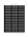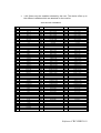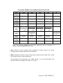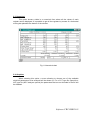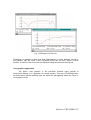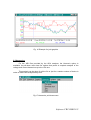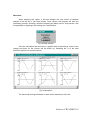
1
SSO
K
RK
OR
WO
NEETTW
ALL N
CA
RIIC
CTTR
R EELLEEC
OR
REE FFO
AR
WA
OFFTTW
A
YSSIISS
ALLY
NA
AN
(Code 775 351)
USER’S GUIDE
(Code M 981 359 / 98 B)
© 1998 CIRCUTOR, S.A. All rights reserved
•
Please do not lose CIR-VISION original diskettes as they will be required in case of program
uninstallation.
•
Do not delete files CIRVIS.SYS & CIRVIS.000 from root directory, since CIR-VISION
authorization would be lost.
INSTALLATION PROCEDURE
Install the original CIR-VISION diskettes executing SETUP.EXE from the first diskette. Software
authorization is loaded in the second diskette.
UPDATE
To update CIR-VISION just install the delivered updated version in the same directory where CIR-VISION
is saved in.
Note: All previous data files will be kept in the directory
REMOVING CIR-VISION FROM A PC TO BE INSTALLED IN ANOTHER PC
To install CIR-VISION in another PC just proceed as follows:
Ø
Uninstall CIR-VISION with the uninstall option of the SETUP.EXE program in the first original
diskette of CIR-VISION.
Ø
Install CIR-VISION in a new PC executing SETUP.EXE from the first diskette.
Ø
Install last updated version whether you have any.
In case that you need to format the hard disk of your PC proceed as follows:
Ø
Transfer the authorization from your hard disk into the CIR-VISION original diskette as for the
first step when removing CIR-VISION.
Software CIR-VISION 1
INDEX
1. Introduction..................................................................................................
Page 3
2. CIR-VISION contents...................................................................................
Page 3
3. Main features................................................................................................ Page 4
4. Installation procedure.................................................................................... Page 5
4.1. System requirements............................................................................. Page 5
4.2. Protection key ....................................................................................... Page 6
5. Run-time......................................................................................................
5.1. File...................................................................................................
• Open...................................................................................................
• Save...................................................................................................
• MCS1..................................................................................................
• Clamp.................................................................................................
• CAVA..................................................................................................
• Network Analyzer................................................................................
Ø AR.4 Analyzer (RS-232).........................................................
Ø AR.5 Analyzer........................................................................
• Export.................................................................................................
• Print....................................................................................................
• Printer Setup.......................................................................................
• Files Setup.........................................................................................
• Exit.....................................................................................................
5.2. Edit........................................................................................................
5.3. Numerical...............................................................................................
5.4. Graphics................................................................................................
5.5. Harmonics..............................................................................................
5.6. Setup.....................................................................................................
5.7. Window..................................................................................................
5.8. Help.....................................................................................................
Page 6
Page 6
Page 6
Page 11
Page 11
Page 12
Page 13
Page 14
Page 14
Page 14
Page 15
Page 16
Page 17
Page 17
Page 17
Page 17
Page 18
Page 18
Page 23
Page 27
Page 28
Page 28
6. Advanced concepts.....................................................................................
Page 29
7. Operations on files.......................................................................................
Page 30
8. RS-232 communications..............................................................................
Page 30
Software CIR-VISION 2
1. Introduction
Welcome to CIR-VISION, the analysis software designed for working under
Microsoft Windows 3.1 or Windows’95 environment. CIR-VISION has many features
which will help you to obtain a quick and accurate analysis of any electrical network
which has been measured by a CIRCUTOR’s AR.4, AR.5, CVM-M, CAVA or MEMORY
CLAMP analyzers.
The CIR-VISION program uses the last features incorporated to the Windows
environment which allow the program being more powerful and easier to use.
2. CIR-VISION Contents
CIR-VISION software is delivered in the following way:
þ Two 3.5” double density diskettes containing the CIR-VISION program
þ User’s guide
þ Registering card
Software CIR-VISION 3
3. Main features
CIR-VISION is a program designed for processing and displaying the data
obtained by a CIRCUTOR’s AR.4 and AR.5 network analyzers or CVM-M memory
peripheral.
Once data has been stored in the memory card, it can be downloaded to a
computer (by means of the memory card reader MCS1) in order to obtain a complete
analysis in a few seconds. Program uses MDI (Multiple Document Interface) system
which allows simultaneously opening several windows, up to a maximum of 16, showing
graphics, harmonic data or numerical charts for their comparison, etc.
The program permits to select the type of file to be analyzed, a graphical or
numerical displaying mode, etc., by means of diverse intuitive menus. Depending on the
selected file different menus will be available.
Graphics
• Ability to make zooms on any graphic and for any period.
• Access more than 40 graphics through different menus.
• Graphics are automatically scaled taking the max. and min. values of each
graphic as the maximum and the minimum.
• At the bottom of each window you can read the instantaneous, maximum and
minimum values, together with the starting and ending date of that
measurement. The value at a determined point is shown moving the mouse
over the graphic.
• All graphics can be copied into the clipboard to be exported to other
applications. It is also possible to save a graphic with a bitmap file format
(*.bmp).
• All graphics are printed out with a headline previously written by the user.
Software CIR-VISION 4
4.0 Installation
Before installing the program check that your system has the minimum
requirements for a proper performance of the program. Once checked, run the
SETUP.EXE file which is included in the installation diskette.
Firstly SETUP enables to choice what we want to do:
- If we choice to install CIR-VISION, the system will ask you in which
subdirectory you want to install the program, once answered, it will complete the
installation in the selected subdirectory. The installation will be ended moving the
authorization to your hard disk.
- If we choice uninstall CIR-VISION the system will ask you in which subdirectory
is the program installed and the authorization will return to the original diskette. So, you
can install CIR-VISION in another PC.
.
Keep installations diskettes since they are required for uninstalling CIRVISION.
.
Second diskette has two authorizations loaded. Second one is to be used
in case first one is lost
.
If you try to install another time without saving the authorization back to the
original diskette an error will appear and CIR-VISION will run in demo version.
.
If a demo version of the program is installed in the computer delete it before
running installation program to avoid possible problems.
+
Fill the registering card and send it back to CIRCUTOR. Once you’ve been
registered as an user, you will receive information about products, updating versions
and the help of our technical staff.
4.1 System requirements
♦
♦
♦
♦
♦
♦
♦
IBM/PC or compatible computer 80386 or higher (486 is advisable)
Minimum 8 MB of RAM
3.5” high density flexible disk drive
Hard disk
VGA colour monitor
Mouse compatible with Windows.
Operative system MS/DOS 5.0 or higher and Microsoft Windows 3.1 or higher.
The above configuration is flexible, any improvement in the equipment
configuration will increase the program efficacy.
Software CIR-VISION 5
4.2 Protection key
The CIR-VISION program is protected against copy by means of a “software”
system. Protection key is automatically saved in the root directory where CIR-VISION is
installed.
CIR-VISION can also running with the old “hardware” protection key with no
need of the new “software” protection.
F Warning! Do not delete nor copy ‘Software’ key from the root directory, since CIRVISION authorization will be lost and program will run in demo mode. The key consists
of files CIRVIS.SYS and CIRVIS.nnn, where nnn will depend on number of users in the
network.
5. Run-time
This chapter explains the use of the different options in the program menus.
5.1 File
With this menu you can access to following options:
• Open: It allows to open a data file for its further analysis.
Fig 1. Opening a file
Available file types:
• *.arm: Stores the main electrical parameters of the mains.
• *.ari: Together with the main electrical parameters of the mains it also stores
a waveform of each period for its later analysis in the PC.
• *.ar4: This file contains data about harmonics.
Software CIR-VISION 6
• *.arp: Stores the periods when the analyzer has been switched off or when a
supply loss has occurred, together with the date when the energy meters
have been reset to zero.
• *.cvm: Stores the main electrical parameters of the mains, those are:
Phase-Neutral Voltage: L1, L2, L3 and III
Max Phase-Neutral Voltage: L1, L2 and L3
Min Phase-Neutral Voltage: L1, L2 and L3
Current: L1, L2, L3 and III
Max Current: L1, L2 and L3
Min Current: L1, L2 and L3
Active Power: L1, L2, L3 and III
Inductive Power: L1, L2, L3 and III
Capacitive Power: L1, L2, L3 and III
Power Factor: L1, L2, L3 and III
Active Energy
Inductive Energy
Capacitive Energy
Frequency
Channel A/D 1
Channel A/D 2
The device also reads negative values if those occur.
• *.cvt: Stores only the variables selected by the user. The device offers up to
180 different variables which are attached on the next list.
Software CIR-VISION 7
CVM-M DEVICE VARIABLES
Nº
0
1
2
3
4
5
6
7
8
9
10
11
12
13
14
15
16
17
18
19
20
21
22
23
24
25
26
27
28
29
30
31
32
33
34
35
36
37
38
39
40
41
42
43
44
45
46
47
48
49
50
51
52
53
54
55
56
57
58
59
VARIABLE
V1
A1
kw1
kvar L1
kvar C1
PF 1
V2
A2
kW2
kvar L2
kvar C2
PF2
V3
A3
kW3
kvar L3
kvar C3
PF3
Vav III N
Aav III
k WIII
kvar LIII
kvar CIII
PF III
Hz
kVA III
V21
V23
V31
Vav III
DC1
DC2
V1mx
A1mx
kW1mx
kvar L1mx
kvar C1mx
PF 1mx
V2mx
A2mx
kW2mx
kvar L2mx
kvar C2mx
PF2mx
V3mx
A3mx
kW3mx
kvar L3mx
kvar C3mx
PF3mx
Vav III Nmx
Aav IIImx
kWIIImx
kvar LIIImx
kvar CIIImx
PF IIImx
Hzmx
kVA IIImx
V12mx
V23mx
Nº
60
61
62
63
64
65
66
67
68
69
70
71
72
73
74
75
76
77
78
79
80
81
82
83
84
85
86
87
88
89
90
91
92
93
94
95
96
97
98
99
100
101
102
103
104
105
106
107
108
109
110
111
112
113
114
115
116
117
118
119
VARIABLE
V31mx
Vav IIImx
DC1mx
DC2mx
V1mn
A1mn
KW1mn
Kvar L1mn
Kvar C1mn
PF 1mn
V2mn
A2mn
KW2mn
kvar L2mn
kvar C2mn
PF2mn
V3mn
A3mn
kW3mn
kvar L3mn
kvar C3mn
PF3mn
Vav III Nmn
Aav IIImn
k WIIImn
kvar LIIImn
kvar CIIImn
PF IIImn
Hzmn
kVA IIImn
V12mn
V23mn
V31mn
Vav IIImn
DC1mn
DC2mn
- kW1
- kvar L1
- kvar C1
- kW2
- kvar L2
- kvar C2
- kW3
- kvar L3
- kvar C3
- kWIII
- kvar LIII
- kvar CIII
- kW1mx
- kvar L1mx
- kvar C1mx
- kW2mx
- kvar L2mx
- kvar C2mx
- kW3mx
- kvar L3mx
- kvar C3mx
- kWIIImx
- kvar LIIImx
- kvar CIIImx
Nº
120
121
122
123
124
125
126
127
128
129
130
131
132
133
134
135
136
137
138
139
140
141
142
143
144
145
146
147
148
149
150
151
152
153
154
155
156
157
158
159
160
161
162
163
164
165
166
167
168
169
170
171
172
173
174
175
176
177
178
179
VARIABLE
- kW1mn
- kvar L1mn
- kvar C1mn
- kW2mn
- kvar L2mn
- kvar C2mn
- kW3mn
- kvar L3mn
- kvar C3mn
- kWIIImn
- kvar LIIImn
- kvar CIIImn
Kwh-1
kwh/1000-1
kvarLh-1
kvarLh/1000-1
kvarCh-1
kvarCh/1000-1
- kwh-1
- kwh/1000-1
- kvarLh-1
- kvarLh/1000-1
- kvarCh-1
- kvarCh/1000-1
kwh-2
kwh/1000-2
kvarLh-2
kvarLh/1000-2
kvarCh-2
kvarCh/1000-2
- kwh-2
- kwh/1000-2
- kvarLh-2
- kvarLh/1000-2
- kvarCh-2
- kvarCh/1000-2
kwh-3
kwh/1000-3
kvarLh-3
kvarLh/1000-3
kvarCh-3
kvarCh/1000-3
- kwh-3
- kwh/1000-3
- kvarLh-3
- kvarLh/1000-3
- kvarCh-3
- kvarCh/1000-3
- PF 1
- PF 2
- PF 3
- PF III
- PF 1 mx
- PF 2 mx
- PF 3 mx
- PF III mx
- PF 1 mn
- PF 2 mn
- PF 3 mn
- PF III mn
Software CIR-VISION 8
• *.cvx: Stores the daily Maximum Power Demand records. Whether the CVM
is provided with a Red-Max board the three tariffs would be also saved in.
• *.cvp: Stores the power supply loss events in the device, so recording the
date and time those occurred.
• *.cve: Stores the state changes in the inputs and outputs for both the CVM-M
and CVM-R10 devices. The date and time of each change are also shown.
• *.arc: This is a special file type, useful for the motor starting analysis. Each
register is a time cycle.
• *.mos: This is a file generated by the AR4 Disturb device. It saves the
waveform.
• *.mop: This is a file generated by the AR4 Disturb device. It saves the date
and time of the incidences.
• *.clp: This is a file generated by the MEMORY CLAMP device. It saves the
data measured.
• *.cav: This is a file generated by the CAVA device. It saves the data
measured.
• *.cap: This is a file generated by the CAVA device. It saves the date and time
of the incidences.
• *.a5m: Stores the main electrical parameters of the mains, those are:
Phase-Neutral Voltage: L1, L2, L3 and III
Max Phase-Neutral Voltage: L1, L2 and L3
Min Phase-Neutral Voltage: L1, L2 and L3
Current: L1, L2, L3 and III
Max Current: L1, L2 and L3
Min Current: L1, L2 and L3
Active Power: L1, L2, L3 and III
Inductive Power: L1, L2, L3 and III
Capacitive Power: L1, L2, L3 and III
Power Factor: L1, L2, L3 and III
Active Energy
Inductive Energy
Capacitive Energy
Frequency
The device also reads negative values if those occur.
Software CIR-VISION 9
•
*.a5t: Stores only the variables selected by the user. The device offers up to
144 different variables which are attached on the next list.
AR.5 DEVICE VARIABLES
Nº
0
1
2
3
4
5
6
7
8
9
10
11
12
13
14
15
16
17
18
19
20
21
22
23
24
25
26
27
28
29
30
31
32
33
34
35
36
37
38
39
40
41
42
43
44
45
46
47
48
49
50
51
VARIABLE
Vp-p 1
Vp-p 2
Vp-p 3
Vp-p III
Vp-n 1
Vp-n 2
Vp-n 3
Vp-n III
A1
A2
A3
A III
kW 1
- kW 1
kW 2
- kW 2
kW 3
- kW 3
kW III
- kW III
kvarL 1
- kvarL 1
kvarL 2
- kvarL 2
kvarL 3
- kvarL 3
kvarL III
- kvarL III
kvarC 1
- kvarC 1
kvarC 2
- kvarC 2
kvarC 3
- kvarC 3
kvarC III
- kvarC III
PF 1
- PF 1
PF 2
- PF 2
PF 3
- PF 3
PF III
- PF III
Hz
k VA
k Wh
- kWh
k varhL
- kvarhL
k varhC
- kvarhC
Nº
100
101
102
103
104
105
106
107
108
109
110
111
112
113
114
115
116
117
118
119
120
121
122
123
124
125
126
127
128
129
130
131
132
133
134
135
136
137
138
139
140
141
142
143
144
145
VARIABLE
Vp-p 1 max
Vp-p 2 max
Vp-p 3 max
Vp-p III max
Vp-n 1 max
Vp-n 2 max
Vp-n 3 max
Vp-n III max
A 1 max
A 2 max
A 3 max
A III max
KW 1 max
- kW 1 max
KW 2 max
- kW 2 max
KW 3 max
- kW 3 max
KW III max
- kW III max
KvarL 1 max
- kvarL 1 max
KvarL 2 max
- kvarL 2 max
KvarL 3 max
- kvarL 3 max
KvarL III max
- kvarL III max
KvarC 1 max
- kvarC 1 max
KvarC 2 max
- kvarC 2 max
KvarC 3 max
- kvarC 3 max
KvarC III max
- kvarC III max
PF 1 max
- PF 1 max
PF 2 max
- PF2 max
PF 3 max
- PF 3 max
PF III max
- PF III max
Hz max
KVA max
Nº
200
201
202
203
204
205
206
207
208
209
210
211
212
213
214
215
216
217
218
219
220
221
222
223
224
225
226
227
228
229
230
231
232
233
234
235
236
237
238
239
240
241
242
243
244
245
VARIABLE
Vp-p 1 min
Vp-p 2 min
Vp-p 3 min
Vp-p III min
Vp-n 1 min
Vp-n 2 min
Vp-n 3 min
Vp-n III min
A 1 min
A 2 min
A 3 min
A III min
kW 1 min
- kW 1 min
kW 2 min
- kW 2 min
kW 3 min
- kW 3 min
kW III min
- kW III min
kvarL 1 min
- kvarL 1 min
kvarL 2 min
- kvarL 2 min
kvarL 3 min
- kvarL 3 min
kvarL III min
- kvarL III min
kvarC 1 min
- kvarC 1 min
kvarC 2 min
- kvarC 2 min
kvarC 3 min
- kvarC 3 min
kvarC III min
- kvarC III min
PF 1 min
- PF 1 min
PF 2 min
- PF2 min
PF 3 min
- PF 3 min
PF III min
- PF III min
Hz min
kVA min
Software CIR-VISION 10
AVAILABLE MEMORY ACCORDING DEVICES AND FILES
TIPOS
128k
*.ARM
640 rec.
200 bytes
*.ARI
128 rec.
1000 bytes
*.ARP
21333 rec.
6 bytes
*.CVM
600 rec.
200 bytes
*.A5M
200 bytes
*.CVT
120000 − 192
4*nº var+10 4 * n º var + 10
bytes
rec.
*.A5T
4*nº var+10
bytes
*.CVP
6 bytes
*.CVX
10 bytes
*.CVE
9 bytes
256k
X
384k
X
512k
X
X
X
X
X
X
X
1200 rec.
1800 rec.
2400 rec.
1200 rec.
240000 − 192
4 * nº var + 10
rec.
1M
5000 rec.
360000 − 192
4 * nº var + 10
rec.
480000 − 192
4 * nº var + 10
rec.
256000 − 192
4 * n º var + 10
1000000 − 192
4 * n º var + 10
rec.
40 rec.
rec.
80 rec.
120 rec.
160 rec.
40 rec.
80 rec.
120 rec.
160 rec.
200 rec.
400 rec.
600 rec.
800 rec.
Note: The memory capability for the AR.4 analyzers can be increased if a
memory card is plugged into the device.
• Save: Permits to save a graphic with a bitmap file format (.bmp) to be further
managed with an image editor such as PaintBrush
• MCS1: Operations with the memory card reader: read the card, delete a file, format
the card and set the communications up.
Communication port parameters are COMx (where x is the communication port
where the MCS-1 is plugged to), 9600, 8, E (even), 1.
Software CIR-VISION 11
Fig. 2 Set-up of the MCS-1 communication port.
•
Clamp: Operations with the Memory Clamp. To download data captured by the
clamp, set the clamp up, and data monitoring, i.e., data visualization in real time.
Communication port parameters are COMx (where x is the communication port
where the clamp is plugged to), 19200, 8, N (none), 1.
Fig.3 Clamp setup (Memory Clamp)
Software CIR-VISION 12
•
CAVA: To download data from CAVA-250, setup actions, and real time data
monitoring.
When selecting option “Read CAVA”, the name of the file and the directory to save
data from CAVA-250 in will be inquired. Data will be saved in the file with an
extension CAV, an also, another file with extension CAP will be created to store
Power ON/Power OFF data from CAVA-250.
The option “CAVA Setup” permits the user to modify CAVA-250 parameters, such
as date, time, period (in seconds), frequency, variable (voltage or current) and
memory type (rotary memory and average flicker).
With the “Monitoring” option, voltage or current data can be real time visualized. See
(Fig.4).
Communication port parameters are COMx (where x is the communication port
where the CAVA-250 is plugged to), 19200, N (none), 1.
Fig.4 CAVA-250 Monitoring option
Software CIR-VISION 13
•
Network Analyzer: This option allows the user to select the AR.4-RS232 analyzer
or the AR.5 analyzer.
AR.4 Analyzer (RS-232)
When selecting option AR.4 Analyzer (RS-232) an screen for the port
configuration and downloading of data in the AR.4 will be shown up.
The option Read AR.4 permits to read ARI/ARM or ARP type files.
Once the type of file to be read is selected, a name for the file and the directory to save
it in can are to be chosen by the user before data transferring process starts.
AR.5 Analyzer
The option AR.5 Analyzer permits the user to transfer data saved in the AR.5.
Clicking this option an screen for the port configuration and downloading of data in the
AR.4 will be shown up.
Before data transferring, check that the programmed communication parameters
coincide with the AR.5’s ones, as well as, that the AR5 meter is not at any setup menu.
Click the option Read AR5 to select the file to be read, and then Read to start data
downloading process through Z-MODEM protocol.
Fig.5 AR.5 data transferring process
Software CIR-VISION 14
• Export: Permits to export a file to ASCII format. A step-by-step example to export a
file to Microsoft EXCEL 5.0 is following attached:
1- Click the option Export in the File menu:
Fig. 6 Export command
2- The next window is then shown up in order to select the file to be
exported. A window requesting for the name that the exported file will
take also appears:
Fig. 7 Export Window
3- Then, the next window is shown up, where the separators for
exporting the file can be choosen.
If the export process is done with Excel spreadsheet do not modify
the separators.
Software CIR-VISION 15
Fig. 8 Export Window
4- Run Excel and click open in the File menu. In the import assistant
select ‘Delimited’ for the file type and click ‘Next’, mark option ‘Space’
and click ‘End’; the file is already imported.
Fig. 9 Microsoft EXCEL 5.0. import assistant
Note: To export harmonics from an ARI type file select the file with extension AR4. This
file is created when any option from the Harmonic menu is used.
• Print: Asks for a headline and sends it to the printer together with the contents of the
active window. If the active window has a chart, then the parameters to be printed
are asked, in addition with the desired time period.
Software CIR-VISION 16
• Setup print: Allows selecting the printer to be used.
• Files Setup: Use this option to select the drivers to perform an analysis of their files.
The installation program load by default all drivers. During program operation those
most interesting for the user can be selected. (see Fig.10).
Fig.10 Driver selection
• Exit: Ends program execution and exits to Windows.
5.2 Edit
This option allows copying an active window into the Windows clipboard for later
attaching it to any text editor, etc.
For more information about the Windows clipboard utility consult the Microsoft
Windows user’s guide.
Software CIR-VISION 17
5.3 Numerical
This option shows a table in a numerical form where all the values of each
register can be displayed. It is possible to get all the registers by means of a horizontal
moving bar placed at the bottom of the window.
Fig.11 Numerical chart
5.4 Graphics
When selecting this option, a menu allowing to choose one of the available
electrical parameters to be analyzed will be shown up. For a CVT type file (Special) or
A5T type file (AR.5 analyzer special) the parameters that are not included in the file will
be disabled.
Software CIR-VISION 18
Fig.12 Graphics menu
Once the parameter has been selected, depending on its nature the program will
ask or not the phase to be analyzed and will show a sub-window with the graphical
representation of the selected parameter.
Fig.13 Voltage graphic
Software CIR-VISION 19
Three fields are shown at the bottom of the window which indicate:
1. Current date and value of the data at the point where the cursor is placed.
2. Minimum value for all the measuring and when it occurred.
3. Same as above but for the maximum value.
In case that there is more than one minimum and maximum value, the minimum
value indicated will correspond to the firstly one found, and the maximum to the last one
found.
In case that the data file is too long to display all data on only one screen, the
graphic could be moved to show all data by means of the horizontal moving bar placed
at the bottom of the window.
Note: Holding the mouse left button pressed, the cursor can be moved along the
window but the value would not be updated.
Exception: In graphics of MOS type files (Disturbances), the horizontal moving bar
permits to pass from one disturbance to another along all the file, so each screen
shows one disturbance (Fig.14).
Following values are shown in the lower part of the window:
1. Record (disturbance in the file), date and present value of point where the
cursor is placed.
2. Maximum and minimum value for all the measurement.
3. Nominal value of voltage (Vn) for the measurement.
4. Trigger factor value (T) for the measurement (consult the user’s guide of the
AR.4 performing as a disturbance analyzer).
Software CIR-VISION 20
Fig.14 Disturbance Graphic (MOS)
Application of the zoom on a graphic
The mouse right button permits to fix the starting and ending points of a zone to
get a zoom from it. A green point-line indicates the beginning of the zoom zone. The
zoom procedure is as follows:
Note: The zoom of a zoom window can be done provided the original screen of the
graphic is open.
All the samples inside the marked period are divided in 57 blocks and the
maximum and minimum value for each block is selected, thus a window-sized graphic is
got to enable the display of all the samples in just one screen. The option of an
increasing zoom is also delivered by means of the automatic scaling when a shorter
period is selected.
Software CIR-VISION 21
Fig. 15 Example of a Zoom In.
Exceptions: In graphics of MOS type files (Disturbances), a zoom between records is
not possible, only the zoom of the visualized record can be done. Within a zoom
window, all values of the record can be displayed using the horizontal moving bar
Joint graphics application
The option ‘Joint graphics’ in the pull-down Window menu permits to
concurrently display 2 or 3 graphics on a same window. That way, CIR-VISION takes
the three latest opened windows from the same file, disregarding either the Zoom or
Joint graphics ones.
Software CIR-VISION 22
Fig. 16 Example for joint graphics
5.5 Harmonics
For the .ARI files provided by the AR.4 analyzer, the Harmonic option is
available. Its pull-down menu has five options that permit a complete analysis of the
voltage and current harmonics up to the 15th one.
This analysis can be done for all the file or just for a certain number of blocks in
order to reduce the analysis delay time.
Fig.17 Harmonics pull-down menu
Software CIR-VISION 23
Waveform
When selecting this option, it will ask whether the user wants a complete
analysis of all the file or just some blocks. Once chosen, the program will start the
calculation process, showing a window indicating the delay time for that process, with
the possibility of stopping it just clicking the Cancel button.
Fig.18 Delay window
Once the calculation has been done, a graphic with six waveforms, three for the
voltage and three for the current, will be shown up, indicating the % of the total
harmonic distortion for each waveform.
Fig.19 Waveform
The horizontal moving bar allows to reach all the waveforms of the file.
Software CIR-VISION 24
Bars graph
This options allows a bars-graphic representation of the % harmonic distortion of
each harmonic (2-15) both for the voltage and the current.
Fig.20 THD% for each harmonic
Numerical chart
This option displays on screen a window with six numerical tables, three for the
voltage phases and three for the current phases.
Like the former two options, before the display of the calculation results, a
window with the possibility of choosing a complete or partial analysis of the file will be
shown up.
Once selected, it will calculate the THD and display the results (see below
figure).
Software CIR-VISION 25
Fig.21 THD% numerical chart
The moving bar allows to reach all the waveforms of the file.
THD (Total Harmonic Distortion)
You can display the time evolution of the total harmonic distortion for the voltage
and the current. This allows us to see the time which corresponds to the higher
harmonic distortion or just to know the average THD.
Fig.22 Evolution graphic of the THD%
Software CIR-VISION 26
RMS
This option allows displaying the time evolution of the R.M.S. voltages and
currents calculated from the stored waveforms.
This time evolution is represented in a bars-graphic form where each phase has
a different identifier colour.
Fig.23 Evolution of voltages and currents
5.6 Setup
The configuration menu allows the units initiation of graphics and tables display only for
current and power.
Fig.24 Unit configuration
When the table or graphic is on display, the configured parameter will be shown in the
selected units.
Software CIR-VISION 27
Exception: The units will not change when units lower than the configured one in the file
are selected. For example: A graphic in mA or A could be visualized when the file is
configured in mA. When the file is configured in A it could only be visualized in A.
5.7 Window
The window menu provides the following options:
• Cascade: The cascade command superposes the windows in the way that
the headlines can be concurrently read. Use this presentation to see the
windows which can be hidden or to arrange the windows of the screen.
• Tile: Arranges the windows in a mosaic format.
• Arrange icons: If some applications are being executed in an icon form, those
can be uniformly arranged at the bottom of the screen with this command.
• Close all: It closes all the windows of the application.
5.8 Help
This option shows help information to the user either about the program
performance or about its own specifications.
The following two options are available:
• Index: Launches a help program about the program, where the user will find
information about its performance. If you are not used to working with this kind
of help, press F1 key to obtain an explanation about the operation of helps in
Windows.
• About: It shows information about the CIR-VISION software that is installed in
the computer, including the version number, the serial number of the program
and the copyright.
Software CIR-VISION 28
6. Advanced concepts
This chapter describes technical aspects about the program, the different kind of files
that it uses, in addition with several concepts which, although are not essential for the
program running, might help the user to optimize the program performance.
Files
There are two files that cannot be deleted, they are in the root directory of your HD and
they are called CIRVIS.SYS and CIRVIS.000
For the *.ari files provided by a CIRCUTOR’s AR.4 analyzer, the own program creates
files with *.ar4 extension where stores the information obtained from the harmonic
calculation by means of the use of the FFT (FAST FOURIER TRANSFORM). Each time
that an .ari file is analyzed, the program will check whether this file was already
previously calculated, searching the name of this file with the .ar4 extension, and in
case that it doesn’t find it, it calculates it and creates the file.
This system has been designed to reduce the delay time in operations that involve a
substantial quantity of calculations, as it is the case of the harmonic calculation from the
waveform.
*.ar4 files can be deleted from the disk at any moment. They just will be again created
when that file is again analyzed.
Alternative ways for printing graphics out
CIR-VISION is a real Windows application that allows transferring graphics between
applications, either copying a window in the clipboard, by pressing the “Prt. Scr.” key, or
saving a graphic in bitmap format (*.bmp). Once one of these operations has been
done, you can go to a Windows application like Paintbrush, Write, etc. and modify and
print the graphic.
One of the advantages of this method is that it offers the possibility of creating
documents with several graphics, combining them as you wish, although this method
would not then allow to see the horizontal axis scales, like are seeing when you get a
print-out from CIR-VISION.
Simultaneous display of several windows
In order to compare several graphic types, the program allows the simultaneous
opening of up to 16 windows which can be either from the same file or different ones.
Depending on the size and resolution of the monitor, graphics will be more or less
clearly displayed on screen.
The windows arrange, like at any window application provided with MDI, can be either
manual or automatically done by means of the different options in the Window menu.
Software CIR-VISION 29
7. Operations on files
Graphics Numerical Export
AR.4
Standard
AR.4
Fast-Check
AR.4
Disturbances
AR.5
Energy
CAVA-250
Memory Clamp
CVM
Memory
*.ARM
*.ARI
*.ARP
*.AR4
*.ARC
*.ARP
*.MOS
*.MOP
*.A5M
*.A5T
*.CAV
*.CAP
*.CLP
*.CVM
*.CVT
*.CVX
*.CVE
X
X
X
X
X
X
X
X
X
X
X
X
X
X
X
X
X
X
X
X
X
X
X
X
X
X
X
X
X
X
X
X
X
X
X
X
X
X
X
X
X
X
X
X
X
X
X
X
X
X
X
X
X
X
X
X
Print-out
Unit
setting
X
X
Harmonics
X
X
X
X
X
8. RS-232 Communications
AR.4-M (RS-232)
AR.5
MCS-1
Memory Clamp
CAVA-250
CVM Memory
Directly COMx
(RS-232)
X
X
X
X
X
Through card
reader (MCS-1)
X
Software CIR-VISION 30
X
Notes
Software CIR-VISION 31