1
EB8 0 0 0 S e r i a l U s e r G u i d e
Chapter 1
EasyBuilder 8000 Installation ................................................................. 5
1.
EasyBuilder 8000 Installation ............................................................................... 5
2.
System Connection ................................................................................................ 9
3.
MT8000 System Settings ........................................................................................ 10
4.
MT8000 Download Setting Screen ........................................................................ 19
Chapter 2
Project Manager Operations ................................................................. 24
Chapter 3
How to Create a Simple Object ............................................................. 32
Chapter 4
Compiling, Simulation and Downloading ........................................... 37
1. Screen Configuration ................................................................................................ 37
2. Compiling.................................................................................................................... 37
3. Simulation ................................................................................................................... 38
4. Downloading .............................................................................................................. 39
Chapter 5
System Parameters ................................................................................ 41
1. [Device Table] ............................................................................................................ 43
2. [Model] ........................................................................................................................ 50
3. [General] ..................................................................................................................... 53
4. [Security] ..................................................................................................................... 56
5. [Font] ........................................................................................................................... 57
Chapter 6
Window Operations ................................................................................ 58
1. Base Window ............................................................................................................. 58
2. Common Window ...................................................................................................... 58
3. Fast selection window .............................................................................................. 59
4. System Message Window ....................................................................................... 60
5. Creating, deleting and setting of a window ........................................................... 61
1
Chapter 7
Event Log ................................................................................................. 66
Chapter 8
Data Sampling ......................................................................................... 74
Chapter 9
Object’s General Attributes .................................................................. 79
1.
Selecting the Connection PLC Device .................................................................. 79
2.
Setting the Reading and Writing Address ............................................................ 80
3.
Using Shape Library and Picture Library .............................................................. 83
4.
Setting Text Content ................................................................................................ 90
5.
Adjusting Profile Size ............................................................................................... 95
Chapter 10
Object’s Security Guard ...................................................................... 96
1. Setting and Changing Password ............................................................................ 96
2. Object’s Safety........................................................................................................... 99
Chapter 11
Index Register ......................................................................................103
Chapter 12
Designing and Using Keypad ............................................................106
Chapter 13
Object ....................................................................................................109
Bit Lamp Object ................................................................................................................ 109
Word Lamp Object ........................................................................................................... 112
Set Bit Object .................................................................................................................... 116
Set Word Object ............................................................................................................... 120
Function Key Object ......................................................................................................... 128
Toggle Switch Object ........................................................................................................ 132
Multi-Switch Object.......................................................................................................... 134
Numeric Input and Numeric Display Objects ................................................................... 138
ASCII Input and ASCII Display Objects .............................................................................. 146
Indirect Window Object ................................................................................................... 149
Direct Window Object ...................................................................................................... 154
Moving Shape Object ....................................................................................................... 157
Animation Object ............................................................................................................. 163
2
Bar Graph Object .............................................................................................................. 169
Meter Display Object........................................................................................................ 174
Trend Display Object ........................................................................................................ 183
Alarm Bar and Alarm Display Objects .............................................................................. 193
Event Display Object ........................................................................................................ 196
Trigger Data Transfer Object ............................................................................................ 204
20. Periodical Data Transfer Object ............................................................................ 207
21. PLC Control Object ................................................................................................. 210
Chapter 14
Creating and Using Shape Library and Picture Library ................218
1.
Creating Shape Library ......................................................................................... 218
2.
Creating Picture Library......................................................................................... 227
Chapter 15
Label Library & Using Multi-Language ............................................234
Chapter 16
Creating and Using Address Tag Library ........................................240
1.
Creating Address Tag Library .............................................................................. 240
2.
Using Address Tag Library ................................................................................... 244
Chapter 17
Transferring Recipe Data ...................................................................245
1. Updating Recipe Data by Using Ethernet. .......................................................... 245
2. Updating Recipe Data by Using CF Card or USB Disk ..................................... 246
3. Transferring Recipe Data ....................................................................................... 246
4. Saving Recipe Data Automatically ....................................................................... 246
Chapter 18
Ethernet Communication and Multi-HMIs Connection. .................247
1.
HMI to HMI Communication.................................................................................. 248
2.
PC to HMI Communication ................................................................................... 251
3.
Operate the PLC connected with other HMIs. ................................................... 254
Chapter 19
HMI State Controlling (System Reserved Register Addresses) ...256
Normal States and Control ........................................................................................... 256
States of Data Input....................................................................................................... 257
3
Recipe Data .................................................................................................................... 257
Task Button and Fast Selection Window ................................................................... 258
Event Logging ................................................................................................................ 258
Data Logging .................................................................................................................. 259
Password and Operation Level ................................................................................... 260
Time of HMI .................................................................................................................... 261
Hardware of HMI ............................................................................................................ 262
The States of Communicating with Remote HMI(s) ................................................. 262
The States of Communicating with PLC .................................................................... 263
4
Chapter 1 EasyBuilder 8000 Installation
1. EasyBuilder 8000 Installation
(1) Software:
Download from EasyBuilder 8000 CD or visit Weintek Labs, Inc.’s website
at http://www.weintek.com to obtain all available software editions
(including Simplified Chinese, Traditional Chinese and English version) and
latest upgraded files.
The EasyBuilder 8000 software is also called EB8000 in the following
illustration of this chapter and the other chapters of the manual.
(2) Hardware Requirements (Recommended):
CPU: INTEL Pentium II or above
Memory: 64MB or above
Hard Disk: 2.5GB or above (Disc space available at least 10MB)
CD-ROM: 4X or above
Display: 256 color SVGA with 800 x 600 resolution or greater
Keyboard and Mouse: One for each
Ethernet: for project downloading/uploading
RS-232 COM: At least one RS-232 serial port available for on-line
simulation
Printer
(3) Operating System:
Windows 2000 /Windows XP
( Windows XP Professional, the maximum number of other computers that are
permitted to simultaneously connect over the network is ten. This limit includes
all transports and resource sharing protocols combined. For Windows XP
Home Edition, the maximum number of other computers that are permitted to
simultaneously connect over the network is five.)
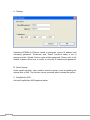
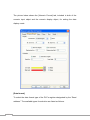
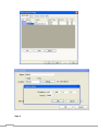
(4) Installation:
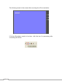
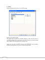
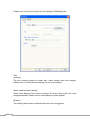
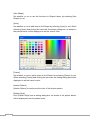
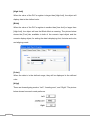
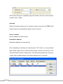
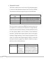
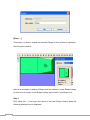
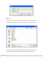
1) When putting the EB8000 CD into CD Rom, the Autorun program will
automatically execute by computer. Or run [Anutorun.exe] from the root
directory manually and the screen shows as below:
5
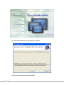
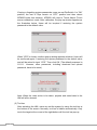
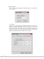
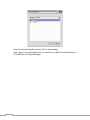
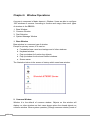
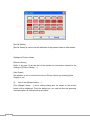
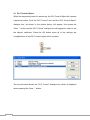
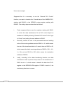
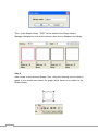
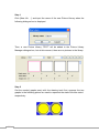
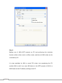
2) Click [Install] and the screen appears as below:
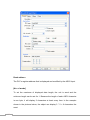
3) Follow the instructions and click [Next].
6
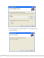
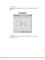
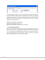
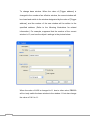
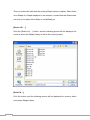
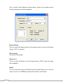
4) Select the target file for software installation or select suggestive path
and then click [Next].
7
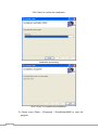
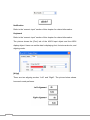
Click “Next” to confirm the installation.
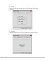
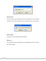
Installation processing
Click” Close” to complete the installation.
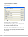
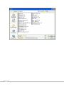
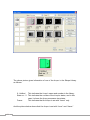
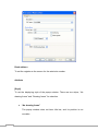
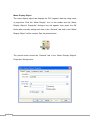
5) Chose menu [Start] / [Programs] / [EasyBuilder8000] to start the
program.
8
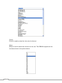
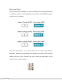
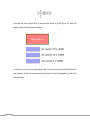
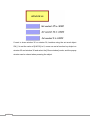
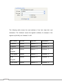
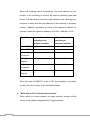
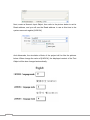
The identification of each selection under the directory of the software:
EasyBuilder8000
EB8000 touch screen editing
software
Project Manager
MT8000 integration management
software
ReleaseNote.pdf
Software version and latest
information
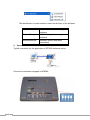
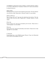
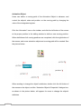
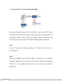
2. System Connection
Typical connection for the application of MT8000 series as below:
Connection interfaces equipped in MT8000:
9
USB Host
Support various devices with USB interface, such as mouse, keyboard, USB
stick, printer…etc.
Ethernet Port
Connected with devices with Ethernet communication function, such as PLC,
laptop…etc; exchange the information via Network.
44 Pin IDE Interface
Enlarge the available hard disk to store a variety of data or information.
Compact Flash card
Support the download/ upload of a project, including recipe transfer, Event Log
Data…etc.
Serial I/O Port
COM ports, RS-232, RS485-2w/4w, can be connected to PLC or other
peripheral devices. Here we view RS-422 the same as RS-485 (4 wire).
Please refer to the appendix in the user manual for correct connection of PLC
and touch screen. Besides, please make sure all dipswitches are on “OFF”
(down) position (defaults of the display).
In addition, Weintek provides aaa and bbb connection cables to expand a
COM port to multiple independent COM ports so that the efficiency of the
operation will be improved. Please refer to the connection illustration in the
manual.
3.
MT8000 System Settings
Before first operating MT8000, users have to complete every system setting.
After the setup, use EB80000 editing software to develop a personal operation
interface.
The following illustrates every system setting respectively.
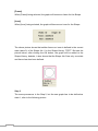
(1)System Reset
Each HMI is equipped with a set of reset button and dip switch. When using
Dip switch to change different modes, corresponding functions will be
triggered. (Please refer to related chapters.)
10
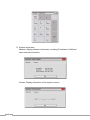
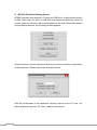
If losing or forgetting system passwords, users can set Dip Switch 1 to “ON”
position, the rest of Dips remain on “OFF” position and then reboot
MT8000.Under this situation, MT8000 will jump to Touch Adjust (Touch
screen calibration) mode. After calibration, the pop-up window appears as
the illustration below. Users will be inquired if restoring the system
password to the default value.
When “YES” is chosen, another pop-up dialog appears as below. Users will
be confirmed again if restoring the system password to the default value
and will be asked to input “YES”. Then click OK. (The default password is
111111. However, other passwords, including download and upload
password, have to be reset.)
Note: When the reset action is be taken, projects and saved data in the
HMI will all be cleared.
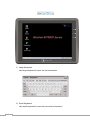
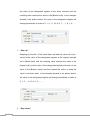
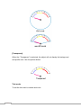
(2) Tool bar
After activating the HMI, users can set the system by using the tool bar at
the bottom of the screen. Normally, tool bar is hidden automatically. Only
touch the target at the cornet of the right-bottom will the tool bar pop up.
11
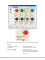
1) Large Keyboard
Use large keyboard to input the text information.
2) Small Keyboard
Use small keyboard to input the numerical information.
12
3) System Information
Network: Display Network information, including IP address of HMI and
other network information.
Version: Display information of the system version.
13
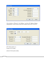
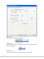
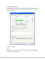
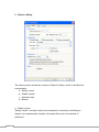
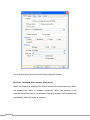
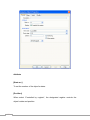
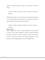
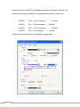
4) System Setting
Set or modify system parameters. Password has to be confirmed in
view of security.
a. Network
Projects can be downloaded to MT8000 via Ethernet so that the IP
address of operation target (HMI) must be correctly set. If “Auto Get IP
Address” is selected, IP address will be automatically assigned from
local DHCP network. While if “IP address get from below” is selected, IP
address and other network information have to be input.
14
b. Time/Date
System time/date will display at the cornet of the bottom-right after the
adjustment.
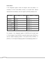
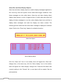
c. Security
Providing stricter security protection for the MT8000. The default of the
password is 111111.
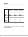
15
Local Password
Password to enter the system
Upload Password
Password to upload the project
Download Password
Password to download the project
Reserved Password
Password reserved for further usage
Password confirmation:
16
d. History
The tab can clear the historical data in the HIM: Recipe, Event log and
Data log.
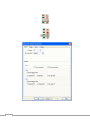
e. Backlight
Using the rolling bottom on the screen to adjust the brightness of LCD.
17
f. CF Card Stat
When HMI detects other new device, this function will be enabled.
18
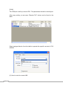
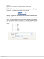
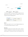
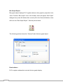
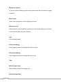
4. MT8000 Download Setting Screen
MT8000 provides two methods: CF card and USB stick, to download a project
to HMI. After insert CF card or USB stick and assign the directory name, all
context under the directory will be downloaded to the HMI. When HMI detects
new peripheral devices, the following screen appears:
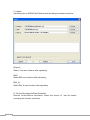
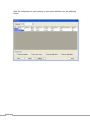
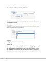
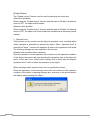
Several functions can be selected at this time and some need the confirmation
of the password. Please refer to the illustration below:
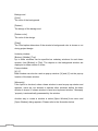
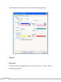
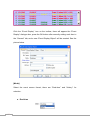
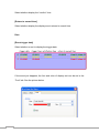
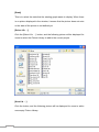
After the confirmation of the password, directory names of the CF card…etc
will be displayed. (pccard: CF Card ; usbdisk: usb device)
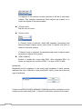
19
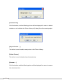
Select the download path and click OK for downloading.
Note: Data to be downloaded will be created from [Build Download Data for
CF/USB Disk] of Project Manager.
20
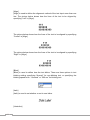
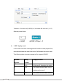
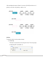
Generally speaking, Project Manager divides the downloaded files into two
directories:
MT8000
store projects
History
The directory will be created when download the historical data.
mt8000
history
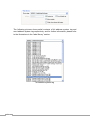
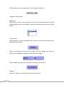
In other words, if location of the saved file as below,
21
the data structure will as follows:
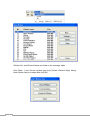
The most upper path should be selected when downloading. In other words,
take the structure above as an example, download must be selected but
mt8000 or history is invalid.
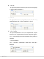
Take the illustration below as another example, usb disk only saves mt8000
directory but not includes history. In this case, users must choose device-0 to
correctly download the file.
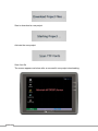
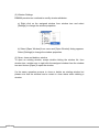
In the process of downloading, screens of HMI change in order:
Stop the current project
22
Start to download a new project
Activate the new project
Scan font file
The screen appears as below after a successful new project downloading.
23
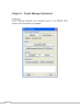
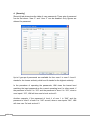
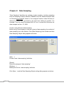
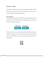
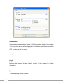
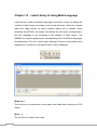
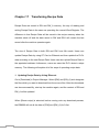
Chapter 2 Project Manager Operations
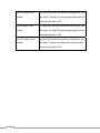
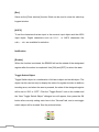
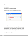
Introduction
Project Manager integrates every available function of the EB8000. Each
function will be introduced in this chapter.
24
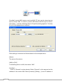
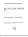
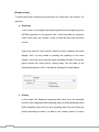
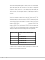
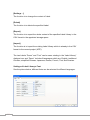
A. Settings
Operating MT8000 by Ethernet needs to designate correct IP address and
necessary password. “Download” and “Reset” functions share a set of
password while “Upload” function uses another password. Please refer to the
related chapters about how to modify or view the IP address and password.
B. Reset System
Under certain situation, users need to reset the system, such as updating the
internal files of HMI. This function can be executed without restart the system.
C. EasyBuilder 8000
Activate EasyBuilder 8000 graphical editor.
25
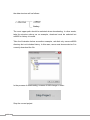
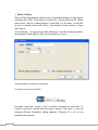
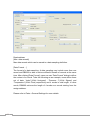
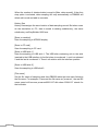
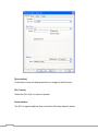
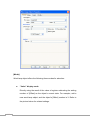
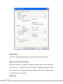
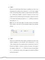
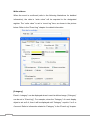
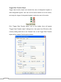
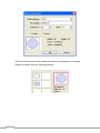
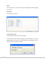
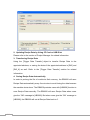
D. Building Download Data from CF Card/USB Stick
Except Ethernet, data also can be downloaded to the MT8000 by CF card or
USB memory stick. The function is for building the download data and the
settings shows as below.
[Select the folder to save CF/USB memory stick data]
Press [Browse] to search for and assign the file path (or directory name) and
then press [Build] to set all contexts of the downloaded data. Users can directly
designate the save location in CF card/ USB stick or copy the entire directory
to CF card/USB stick after completely building the data.
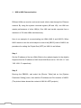
Insert CF card or USB stick and assign the name of the file, EB8000 will start
downloading the whole content of the file to HMI.
Note: Save location should be the name of directory and avoid designating
only root directory.
For example, both c:\” and f:\\” are illegal names.
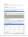
[Project]
26
Use EB8000 to configure the context of display (*.mtp file) and then compile it
to *xob file for HMI terminal. The desired *xob file for CF card can be selected
by using this function.
[Recipe (RW)]
RW Recipe file for CF card can be selected by this function. The max effective
size of the file is 64K. Please refer to “Receipt Transfer” for more details.
[Recipe A (RW_A)]
RW_A Recipe file for CF card can be selected by this function. The max
effective size of the file is 64K. Please refer to “Receipt Transfer” for more
details.
[Event log]
Event log file for CF card can be selected by this function. Please refer to
“event log object” for more details.
[Data log]
Data log file for CF card can be selected by this function. Please refer to “data
log object” for more details.
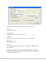
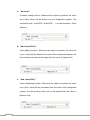
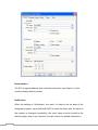
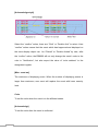
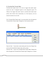
E. Download
Downloading files to the MT8000 through Ethernet. Press the [Download]
button and the dialog appears as below:
27
[System]
Check [System] to update all of the kernel programs of HMI.
[Project]
EB8000 are able to have the content of screen configuration (MTP file)
compiled and get *.xob file for MT8000.The desired *.xob file downloaded to
the terminal can be selected.
[RW]
Select the desired RW recipe data to be downloaded to MT8000. The max size
available is 64K Please refer to [recipe transfer] chapter for further information.
[RW_A]
Select the desired RW_A recipe data to be downloaded to MT8000. The max
size available is 64K. Please refer to [recipe transfer] chapter for further
information.
[Event log]
28
Select the desired event log file to be downloaded to MT8000. Please refer to
“Event log object” for more details.
[Data log]
Select the desired data log file to be downloaded to MT8000. Please refer to
“Data log object” for more details.
[Reset recipe]
Check [Reset recipe] to set all figures of recipe to 0 before the process of
downloading.
[Reset event log]
Check [Reset Event log] to clear all of the event log files in HMI before the
process of downloading.
[Reset data log]
Check [Reset data log] to clear all of the data log files in HMI before the
process of downloading.
29
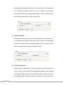
F. Upload
Uploading files to MT8000 by Ethernet and the dialog box shows as below:
[Project]
Select *.xob save location after uploading.
[RW]
Select RW save location after uploading.
[RW_A]
Select RW_A save location after uploading.
G. On-line Simulation/Off-line Simulation
Execute On-line/Off-line Simulation. Select the source of *.xob file before
executing the function as follows:
30
31
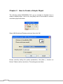
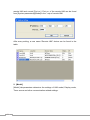
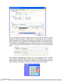
Chapter 3 How to Create a Simple Object
The following takes MITSUBISHI PLC as an example to illustrate how to
create a simple project. First of all, click [New] icon on the toolbar to create a
new blank project as below:
Select HMI Model and Display mode and then click OK.
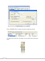
Except correctly setting the system parameters, click [New…] function on
Device Table to add a new device. The settings are as below:
32
Device “MISUBISHI FX0n” is added to the Device Table after click OK.
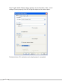
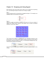
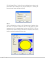
If a toggle switch would like to be added, click the object buttons showed as
follow.
33
New Toggle Switch Object dialog appears as the illustration. After correct
settings of each property, click OK and put the object to the desired place.
Finished window 10 is as below and a simple project is completed.
34
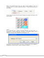
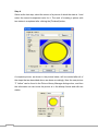
After the file is saved, users select [Compile] function icon to examine if the
screen configuration is correct.
If the compiling result shows as below which means no error exists, then click
the icon to execute the Off-line Simulation.
35
The following screen is the screen after executing the off-line simulation:
If On-line Simulation needs to be done, click the icon for processing after
connecting the device.
36
Chapter 4 Compiling, Simulation and Downloading
A complete design procedure includes: screen configuration, compiling,
simulating and downloading.
Every step is introduced in this chapter.
1. Screen Configuration
Varied screens can be configured by the EB8000 and the edited context is
saved as a *.mtp file.
2. Compiling
After screen configuration (*.mtp file), transfer *.mtp file to *.xob format for
MT8000
downloading
by
using
compiling
function.
Click
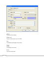
icon on tool bar and [Compiling] dialog
appears as below:
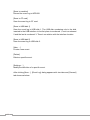
In [Compiling] dialog, [Project name] indicates the name of current
configuration file while [XOB file name] indicates the name of compiled file.
37
Check [Build font files] will re-build a new font file when compiling every time. If
no change in the text context of an object (including the font), cancel this
function so as to accelerate the compiling. Click [Compile] and the following
information displays on [Compiling] dialog:
Font Files
The font files for displayed text which will be downloaded to the MT8000.
Object Size
The size of the compiled file
Library Size
The size of shape library and picture library
Font Size
The total size of font files.
Message “0 error” means a successful compiling and then other simulation
functions can be continued. If an error exists, users should follow instructions
to correct errors.
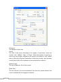
3. Simulation
There are two simulations: Off-line simulation & On-line simulation. By virtual
device, PC simulates the operations of PLC without connecting to PLC. On the
contrary, On-line simulation is executed by connecting with PLC and
accurately setting the communication parameters. When simulating on PC, if
the control target is a local PLC (i.e. the PLC directly connected to PC), there’s
a 10 mins simulation limit.
Users can find Off-line simulation and On-line simulation functions from two
ways:
A)
Project Manager
B) Clicking
of the EB8000.
38
,
icons from tool bar
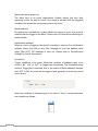
4. Downloading
After the completion of the simulation and the confirmation of the screen
configuration, next step is to download *.xob file to MT8000. Downloading
*.xob file can be done by:
A)
[Download] function from Project Manager. Please refer to” Project
Manager” related chapters.
B)
Click
icon from tool bar of the EB8000 and [Download]
dialog appears as below:
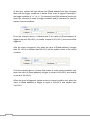
[Download] dialog settings:
[HMI IP]
Assign the download target IP
[Password]
Input password. Please refer to the “hardware setting” related chapter.
[Reset recipe]
39
If the function is selected, all recipe figures will be set to 0 before downloading.
[Reset event log]
If the function is selected, all event log files saved in the MT8000 will be
cleared before downloading.
[Reset data log]
If the function is selected, all data log files saved in the MT8000 will be cleared
before downloading.
[Start system after download]
If the function is selected, MT8000 reboots after downloading is done.
[Update Drivers]
If the function is selected, PLC drivers will be updated. Under the
circumstances of remaining PLC types unchanged, cancel this function to
shorten the downloading time.
Click [Download] to execute downloading operation. Downloaded files will
display on the message dialog.
40
Chapter 5 System Parameters
In the EB8000, select menu [Edit]/[System Parameters…] and the system
parameter setting dialog appears as follows:
41
System parameters are divided into five parts: [Device Table], [Model],
[General], [Security] and [Font] which are introduced respectively in this
chapter.
42
1. [Device Table]
[Device Table] parameters determine all of the characteristics of each device
controlled by a HMI. These devices include PLC, remote HMI and PC. When
open a new *.mtp file, a default device: “Local HMI” is in the table. “Local HMI”
is used to identify current HMI .Each *.mtp should at least include a “Local
HMI” device.
Click [Settings…] to open [Local HMI] dialog box. From the illustration below,
the property of local HMI is “HMI” and the location is “Local”.
The procedure to create a new device:
(1) How to control a local PLC
So-called “local PLC” means a PLC is directly connected to local HMI. To
control a local PLC should add this type of device. Click [New…] and the
following [Device Properties] dialog appears. Correctly fill in all of the
properties as required.
43
Each setting is introduced as follows based on the example above.
[Name]
The name of the device.
[HMI] or [PLC]
If connecting device is PLC, then select “PLC
[Location]
“Local” or “Remote” can be selected. Select “Local” in this example.
[PLC Type]
Select the type of PLC.
[PLC I/F]
Four PLC interfaces are available:”RS-232”, “RS-485 2W”, “RS232-485 4W”,
and “Ethernet”.
If the interface is “RS-232”, “RS-485 2W”or “RS232-485 4W”, click [Setting…]
and [Com port setting] dialog appears as below. User should correctly set the
communication parameters.
44
If the interface is “Ethernet”, click [Setting…] and then [IP Address Setting]
dialog appears. Users should correctly set IP address and Port No. of the PLC.
[PLC default station no.]
Number of PLC station.
[Interval of block pack (words)]
45
If the value of command to target address is smaller than the value of [Interval
of block], several commands can be combined to one command.
[Max. command size (bytes)]
The maximum size (bytes) of the command can be sent to the device.
After every setting, a new name “Local PLC” device can be found on the table.
(2) How to control a remote PLC
So-called “remote PLC” means a PLC is directly connected to a remote HMI.
To control a remote PLC should add this type of device. Click [New…] and the
following [Device Properties] dialog appears. Correctly fill in all of the
properties as required.
46
Each setting is introduced as follows based on the example above.
[Name]
The name of the device.
[HMI] or PLC]
If connecting device is PLC, then select “PLC”
[Location]
“Local” or “Remote” can be selected. Select “Remote” in this case and set the
address of the remote HMI. Select [Location]/ [Setting…] to set the IP address
of the remote HMI.
[PLC Type]
Select the type of PLC
[PLC I/F]
The type of interface for remote PLC. If COM port is used by remote PLC,
interface ”RS-232”, “RS-485 2W” or “RS232-485 4W” can be selected.
[PLC default station no.]
The No. of PLC station.
47
[COM]
The COM port used by a remote PLC. The parameters should be correctly set.
After every setting, a new name “Remote PLC” device can be found in the
table.
Select assigned device from the table to operate the specific content of PLC
address.
(3) How to control a remote HMI
48
So-called “remote HMI” means a non-local HMI. PC also can be viewed as one
kind of remote HMI. To control a remote HMI should add this type of device.
Click [New…] and the following [Device Properties] dialog appears. Correctly
fill in all of the properties as required.
Each setting is introduced as follows based on the example above.
[Name]
The name of the device
[HMI] or [PLC]
If connecting device is HMI, then select “HMI”
[Location]
“Local” or “Remote” can be selected. Select “Remote” in this case and set the
address of the remote HMI. Select [Location]/ [Setting…] to set IP address of
49
remote HMI and correct [Port no.]. Port no. of the remote HMI can be found
from [System parameters]/[Model] in the *.mtp of remote HMI.
After every setting, a new name “Remote HMI” device can be found in the
table.
2. [Model]
[Model] tab parameters determine the settings of HMI model, Display mode,
Timer source and other communication related settings.
50
[HMI model]
Select current HMI model as illustration below.
[Display mode]
Select the mode of display. “Landscape” is the normal display while “Portrait”
is the vertical display.
[HMI station no.]
Set the no. of HMI station. If no particular purpose, select default.
51
[Port no.]
Set the port no. for HMI. If no particular purpose, select default.
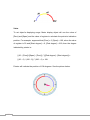
[Time source]
Set the source of timer. The time of the timer is used by such as [Data Log],
[Event Log] ….etc. objects which needs the time records.
Selecting “Internal clock” demonstrates the time signal comes from internal
clock of the HMI.
Selecting “External clock” demonstrates the time signal comes from external
device. The correct address source of time signal is necessary in this situation.
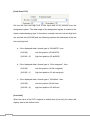
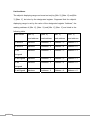
Take the illustration below as an example. “TV” indicates the time from Local
PLC. The contexts of 6 consecutives addresses starting from 0 show as
follows:
TV 0 -> Sec.
TV 1 -> Min.
TV 2 -> Hr.
TV 3 -> Day
TV 4 -> Month
TV 5 -> Year
52
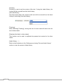
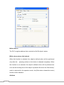
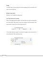
3. [General]
[General] tab parameters determine all properties related to screen operations.
Each setting is introduced as follows:
[Fast selection button]
The settings of all attributes for Fast selection window which is designated as
window number 4.
53
[Attribute]
Enable or disable a Fast Selection window. After selecting “Enable”,
click [Setting…] to set the personality attributes of the buttons
including color and text.
[Position]
Select the location of the Fast select button. If “Left” is chosen, the
button will show up at the corner of the left-bottom. If “Right” is chosen,
the button will show up at the corner of the right-bottom.
[Screen saver]
[Back light saver]
If the untouched duration of screen is equal to this value, back light
shuts off. The setting unit is minute. Back light is triggered once the
screen is touched.
[Screen saver]
If the untouched duration of screen is equal to this value, the current
screen automatically switches to the assigned [Saver window no.].The
setting unit is minute. If “none” value is selected, screen saver function
is disabled.
[Saver window no.]
When executing screen saver function, [Saver window no.] designates
the screen to be switched.
[Option]
[Startup window no.]
Select the window after HMI is started up.
54
[Extra no. of event]
The default of number of events in the system is 1000 in total. If users
would like to add more records, the setting value can be modified up
to 10000.
[Common window]
The objects of the common window (window 6) will be in each base
window. This selection determines these objects are placed on or
under the objects of the base window.
[Cursor color]
Set the color of cursor.
[Cursor color]
If “Control” mode is selected, when HMI operates, [Animation] and
[Moving Shape] display above other kinds of objects and with no
relation to the built ranking.
If “Nature” mode is selected, the displayed sequence of objects show
according to objects’ built priority.
[RW1 enabled]
Enable or disable the recipe data RW1. After activating RW1, an
object can operate the content of RW1 .The size of RW1 is 64K.
[Keyboard]
[Keyboard] function displays on the screen with keyboard. If these screens
represent the use of [Numeric Input] and [ASCII Input], users can select the
type of keyboard.
If users would like to build a keyboard, keyboard should be configured on the
existing screen and select [Add…] function to add these windows to the table.
55
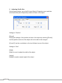
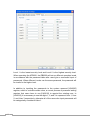
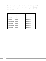
4. [Security]
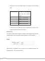
[Security] tab determines the table of user passwords. Three sets of password
can be set where “User 2” and “User 3” can be disabled. Only figures are
allowed for password.
Up to 6 groups of passwords are available for from user 1 to user 3. Level 1
stands for the lowers authority while level 6 stands for the highest authority.
In the procedure of operating the passwords, HMI views the lowest level
matching the input password as the current operating level. In other words, if
the password of level 2 is “123” and the password of lever 6 is “123”, when a
user inputs “123”, HMI will view user’s level as level 2.
Another example: if the password of level 4 of user 1 is “246” and the
password of level 2 of user 3 is “246” as well, when a user inputs “246”, HMI
will view user 3’s level as level 2.
56
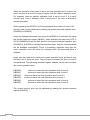
5. [Font]
[Font] tab determines the font of non-ASCII strings.
[Fonts for non-ASCII strings]
This table lists the fonts for non-ASCII strings. If users use the fonts of
non-ASCII strings without choosing the font from [Fonts for non-ascii strings]
table, EB8000 will automatically pick up these fonts.
Users can test which non-ASCII strings in the WINDOWS can be used in
MT8000 and add them to [Fonts for non-ASCII strings] table.
57
Chapter 6 Window Operations
A screen is composed of basic element—Window. Users are able to configure
1997 windows or screens. According to function and usage, there are 4 types
of windows in the EB8000.
1. Base Window
2. Common Window
3. Fast Selection
4. System Message Window
1. Base Window
Base window is a common type of window.
Except for primary screen, it is used on:
a. Foundation base: used as a background of other windows.
b. Keyboard window.
c. Pop-up window for function key objects.
d. Pop-up window for direct and indirect windows
e. Screen saver
The illustration below is the screen of startup which uses base window.
2. Common Window
Window 4 is the default of common window. Objects on this window will
display on other windows so that users always place the shared objects on
common window. When system operates, [Change common window] mode of
58
the function key can be used to change the source of common window. For
example, change the common window from window 4 to window 20.
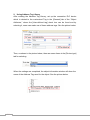
3. Fast selection window
Window 3 is defined as Fast Selection Window. This window can co-exist with
base window. Therefore, generally speaking, it is used by the common-used
operation buttons as the picture below:
When using Fast Selection Window, except creating window 3 first, each
function of Fast Selection button should be set. The [Startup] on the picture
above is the Fast Selection button which is used to change the appearance
and the disappearance of the Fast Selection. Every setting of the Fast
Selection button is in System Parameter Settings. Please refer to the
illustration below.
59
Except switching the appearance and the disappearance of the Fast Selection
by Fast Selection button, system register also provides the following
addresses for users who are able to control Fast Selection and Fast Selection
button by the operation of the values in the address. Please refer to “system
register” for further introduction.
[LB9013] Enable/Disable Fast Selection
[LB9014] Enable/Disable Task button
[LB9015] Enable/Disable Fast Selection/ Task button
4. System Message Window
Window 5 and Window 6 are the defaults of system message window. Among
them, Window 5 is the “PLC Response” message window. When the signal of
PLC is unreceivable, the message window will pop up automatically. Window 6
is the message window for “HMI Connection”. When connection of remote HMI
fails, the message window will pop up automatically.
60
5. Creating, deleting and setting of a window
The picture below displays the window information of the EB8000. The
following section introduces how to create and set these windows.
(1) Creating a window
There are two ways to create a window: a) selecting desired window number
on the window tree and right click Select [New] on the message dialog and
click confirm after the completion of all settings. Please refer to the example
below:
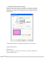
61
[Name]
The name of the window
[Window no.]
The No. of the window, from 3 to 2000.
Size
The [Width] and [Height] of the window.
Frame
[Width]
The [Width] of the frame.
[Color]
The color of the frame.
62
Background
[Color]
The color of the background.
[Pattern]
The design of the background.
[Pattern color]
The color of the design.
[Filled]
The Filled option determines if the window’s background color is shown or not
during project design.
Underlay window
[Bottom], [Middle], [Top]
Up to three windows can be specified as underlay windows for each base
window, from [Bottom] to [Top]. The objects on the background window are
displayed on base window in order.
Popup window
[X], [Y]
Base window can also be used as pop-up window. [X] and [Y] set the pop-up
location of the base window.
[Monopoly]
If the option is checked, when a base window is used as pop-up window and
appears, users are not allowed to operate other windows before the base
window is closed. If a base window is used as a keyboard window,” Monopoly
“property is automatically possessed by the window.
Another way to create a window is select [Open Window] from menu and
[Open Window] dialog appears. Please refer to the illustration below.
63
Window No. and Window Name are listed on the message table.
Click [New…] and choose window type from [Select Window Style] dialog.
New window can be created after click OK.
64
(2) Window Settings
EB8000 provides two methods to modify window attributes:
a) Right click on the assigned window from window tree and select
[Settings] to change the window properties.
b) Select [Open Window] from menu and [Open Window] dialog appears.
Select [Settings] to change the window properties.
(3) Open, close and delete a window
To open an existing window, except double clicking the window No. from
window tree, another way is right click the assigned window from the window
tree and choose [Open] to open the window.
It’s the same operation process to close or delete an existing window but
please note that the window has to remain in close status when deleting a
window.
65
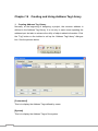
Chapter 7 Event Log
“ Event log” is used to identify the content of an event and the conditions
triggering this event. In addition, the triggered event (sometimes it is called
alarm) and the processing procedure of the event can be saved to the
designate location through the EB8000 as eventlogyyyymmdd.evt format
where yyyymmdd indicates the creating time and is set by the system. For
example, a file name of event, logeventlog20061127.evt, means the file is
created on Nov. 27, 2006.
Creating a new data log
Accompanied with alarm bar, alarm display and event display, users are able
to clearly understand the life cycle of whole event from happening, waiting,
processing to alarm disappearing. Before using these objects, the content of
an event has to be identified first.
Click the [Alarm(Event Log)] icon, and [Event Log] dialog appears as below:
66
[Category]
The EB8000 provides category function and divides an event into 0~255
classifications. Alarm Bar、Alarm Display and Event Display can limit the
displayed classifications.
[Catalog] selection determines the event catalog of current event. New added
event type is determined by this function.
The [1] of 0[1] in the above illustration demonstrates only one existing
identified event in the classification 0.
History files
History files determines the save location of an event log. However, when
users simulate on PC, files will be saved on the eventlog subdirectory, the
same the subdirectory of EasyBuilder8000.exe.
67
[Save to machine]
Record the event log to MT8000.
[Save to CF card]
Save the event log to CF card.
[Save to USB disk 1]
Save the event log to USB disk 1. The USB disk numbering rule is: the disk
inserted to the USB interface in the first place is numbered 1, next is numbered
2 and the last is numbered 3. There’s no relation with the interface location.
[Save to USB disk 2]
Save the event log to USB disk 2.
[New …]
Create a new event.
[Delete]
Delete a specific event.
[Settings …]
Modify the definition of a specific event.
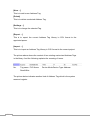
After clicking [New…], [Event Log] dialog appears with two tabs and [General]
tab shows as below:
68
[Category]
The category of the event.
[Level]
The level of the event: According to the degree of importance, users can
choose ”Low”, “Middle”, “High”, or “Emgc”. When the number of event log is
more than max number available in the system (the default is 1000, please
refer to [General] of System Parameters to add extra records), less important
events (lower level) will be deleted and new events will be added in.
[Address type]
The type of address—Bit or Word mode.
[Scan time]
The time interval of an event examination. By scan time, system checks if the
event is satisfied with the triggered conditions.
69
[Delay time when power on]
The delay time of an event examination. System delays this time after
rebooting so that it’s able to check if the event is satisfied with the triggered
condition and avoids the unnecessary event log record.
[Read address]
By reading the read address, system obtains the figure to check if an event is
satisfied with the triggered condition. Please refer to Parts/General Settings for
further details.
[Notification address]
When an event is triggered, the specific message is sent out from Notification
address. Select [Set ON] to send ON message out from the address while
select [Set OFF], Off message is sent out. Please refer to Parts/General
Settings for further information.
[Condition]
Trigger conditions of an event. When the condition of [Address type] of an
event is “Bit”, “ON” or “OFF” of Trigger can be selected. The illustration below
shows if Trigger[On] is selected, that is, the status of [Read address] changes
from OFF to ON, an event will be triggered and generate an event log record
(or an alarm).
When the condition of [Address type] of an event is “Word”, several selections
are available as follows:
70
At this time, system will read values from [Read address] and then compare
them with the trigger conditions to decide if the event is trigged. Especially if
the trigger condition is ”==” or <>”, [In tolerance] and [Out tolerance] can be set
where [In tolerance] is used for trigger condition and [In tolerance] is used for
system’s normal condition.
From the example above, it indicates that if the value of [Read address] is
bigger or equal to 29(=30-1) or smaller or equal to 31(=30+1), the event will be
triggered.
After the event is triggered, only when the value of [Read address] is bigger
than 32( =30+2) or smaller than 28(=30-2) will the system return to the normal
condition.
From the example above, it shows that system is under normal condition only
when the value of [Read address] is bigger or equal to 28(=30-2) and smaller
or equal to 32(=30+2).
When the event is triggered, system returns to normal condition only when the
value of [Read address] is bigger or equal to 29(=30-1) and smaller than
31(=30+1).
71
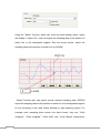
Please refer to the picture below for the settings of [Message] tab.
Text
[Content]
The text context showed on alarm bar、alarm display and event display.
Please refer to “Parts/General settings” for more information.
[Write value for event display]
When event display of the event is touched, the write value is sent out to the
assigned address. Please refer to event display of parts chapter.
[Buzzer]
The warning alarm can be selected when an event is triggered.
72
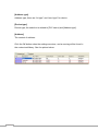
After the completion of each setting, a new event definition can be added as
below:
73
Chapter 8 Data Sampling
“Data Sampling” identifies the method of data sampling, including sampling
time and sampling location. Besides, EB8000 saves the obtained sample data
as filenameyyyymmdd.dtl format to the assigned location where filename is
defined by users and yyyymmdd is the built time setting by system. For
example, if the file name is presser20061127.evt, it means the file saves the
data sampled on Nov. 27, 2006.
Create a new defined of data sampling
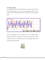
Before using Trend display to view the content of data sampling, the method of
data sampling has to be defined. Click [Data Sampling] from toolbar and then
Data Sampling Object dialog appears as below:
[New …]
Create a new “data sampling” definition.
[Delete]
Delete the assigned “data sampling”.
[Settings …]
Modify and set the “data sampling” definition
Click [New…] and the Data Sampling Object setting dialog appears as below:
74
Read address
[Max. data records]
Max data records which can be saved to a data sampling definition.
[Data Format …]
The format of a data sampling: A data sampling may include more than one
record and EB8000 is able to retrieve different formats of records at the same
time. After clicking [Data Format], users can use “Data Format” dialog to define
the content of a record. Take the following as an example, users define three
set of data: “Index”(16-bit Unsigned) 、 “Pressure 1”(16-bit Signed) and
“Temperature”(32-bit Float) respectively and 4 words in total length. In other
words, EB8000 retrieves the length of 4 words as a record starting from the
assign address.
Please refer to Parts—General Settings for more details.
75
[PLC name]
Select the target PLC of data sampling.
[Clear address]
If the status of the assigned address is ON, obtained data will be cleared and
the number of data sampling will be set to zero.
[Hold address]
If the status of the assigned address is ON, sampling will be paused until the
status of assigned address returns to OFF. Please refer to Parts—General
Settings for other details.
Sample mode
EB8000 provides two method of sampling: “Periodical” and “Trigger”. If
“Periodical” mode is selected, EB8000 samples the data by a fixed time
frequency. Users have to set the sampling time interval.
76
If “Trigger” mode is selected, users can use a specific address status to trigger
the data sampling.
[Mode]
Mode determines the condition to trigger the data sampling. Multiple choices
are as follows:
“OFF->ON”
“ON->OFF”
“ON<->OFF”
sampling is triggered.
If the assigned address status is from OFF to ON, data
sampling is triggered.
If the assigned address status is from ON to OFF, data
sampling is triggered.
If the assigned address status is changed, data
Please refer to Parts—General Settings for more details.
[Auto stop]
77
When the number of obtained data is equal to [Max. data records], if the Auto
stop option is selected, data sampling will stop automatically or EB8000 will
delete old record and add in new data.
History files
History files assigns the save location of data sampling record. But when users
do the simulation on PC, data is saved to datalog subdirectory, the same
subdirectory as EasyBuilder 8000.exe.
[Save to machine]
Save the sampling to MT8000 display.
[Save to CF card]
Save the sampling to CF card.
[Save to USB stick 1]
Save the sampling to USB stick 1. The USB stick numbering rule is: the stick
inserted to the USB interface in the first place is numbered 1, next is numbered
2 and the last is numbered 3. There’s no relation with the interface position.
[Save to USB stick 2]
Save the sampling to USB stick 2.
[File name]
Set the file name of sampling and then EB8000 adds the time mark following
the file name. For example, if users set the file name as ”pressure”, the real file
name saved will become pressure20061127.dbl where 20061127 stands for
the built date.
78
Chapter 9 Object’s General Attributes
The contents of object’s general attribute setting include:
1.
2.
3.
4.
5.
Selecting the Connection PLC Device
Setting the Reading and Writing Address
Using Shape Library and Picture Library
Setting Text Content
Adjusting Profile Size
1.
Selecting the Connection PLC Device
When using some objects, selection of the connection PLC device is required.
See the picture below, [PLC name] is to indicate the name of the connection
PLC device. The picture shows that there are two PLC devices available for
selection: “Local HMI” and “Allen-Brandley DF1.” These listed available PLC
devices are sourced from “device table” in “system parameters.”
79
2.
Setting the Reading and Writing Address
The above picture shows that the following items are contained in Reading and
Writing Address settings:
[Device type]
In selection of device types, when the connection PLC device is different, there
will be different device types for selection.
[Address]
Setting the reading and writing address.
[System tag]
Address tag includes “system tag” and “user-defined tag.” System tag,
including bit address system tag and word address system tag, is to reserve
the addresses of particular purposes for the system. When selecting “system
tag,” in addition to that [Device type] will show the content of “system tag,”
[Address] will indicate the selected system tag. Refer to the picture below.
80
The following pictures show partial contents of bit address system tag and
word address system tag respectively, and for further information, please refer
to the illustrations in the “label library” section.
bit address system tag
81
word address system tag
[User-defined tag]
“User-defined tag” is for users to use the tag to define regularly used
addresses and then to enhance the utility of MTP file. The way of using
“user-defined tag” is the same as using “system tag,” and for further
information, please refer to the illustrations in the “label library” section.
[Index register]
Refer to the illustrations in “index register” section for information on if it is
necessary to select “index register” or not.
Selecting Numeric Type
The EB8000 supports the following listed numeric types. It is necessary to
select the proper numeric type, especially when using address tag.
82
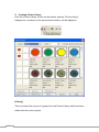
3. Using Shape Library and Picture Library
Shape Library and Picture Library are available for some objects to enhance
the object’s visual effects. See the picture below, go to the Bit Lamp Object’s
Properties menu and then click the [Shape] tab to set up Shape Library and
Picture Library.
The descriptions of each item’s setting on the [Shape] menu are as follows:
Settings of Shape Library
[Shape Library …]
Refer to the part (I) at the last of this section for information related to the
settings of [Shape Library …].
83
[Use Shape]
Set whether or not to use the functions in Shape Library by selecting [Use
Shape] or not.
[Inner]
Set whether or not to add inner to the Shape by selecting [Inner] or not. When
selecting [Inner] and clicking the color tab, the setting dialog box, as shown in
the picture below, will be displayed to set the inner’s color.
[Frame]
Set whether or not to add a frame to the Pattern by selecting [Frame] or not.
When selecting [Frame] and clicking the color tab, the setting dialog box will be
displayed to set the frame’s color.
[Interior Pattern]
[Interior Pattern] is used to set the color of the interior pattern.
[Pattern Style]
Click [Pattern Style] and a setting dialog box, as shown in the picture below,
will be displayed to set the pattern style.
84
[Set All States]
[Set All States] is used to set all attributes of the present state to other states.
Settings of Picture Library
[Picture Library]
Refer to the part (II) at the last of this section for information related to the
settings of [Picture Library …].
[Use Graph]
Set whether or not to use the functions in Picture Library by selecting [Use
Graph] or not.
(I)
How to set [Shape Library …]
Click [Shape Library …] and a setting dialog box, as shown in the picture
below, will be displayed. From the dialog box, you can see that the presently
selected pattern is marked with a red frame.
85
The above picture gives information of one of the Shapes in the Shape Library
as follows:
0: Untitled This indicates the Shape’s name and number in the library.
State no.: 2 This indicates the number of the Shape’s states, and in this
case, it shows the Shape possesses two states.
Frame
This indicates that the Shape is set with “frame” only.
And the picture below shows that the Shapes is set with “inner” and “frame.”
86
Refer to the illustrations in the “Setting-up and using Shape Library and Picture
Library” section for the details about all of the settings in the “Shape Library’s
setting dialog box.” After completing all the settings and clicking [OK], the
selected Shape will be applied to the object, as shown in the picture below.
(II) How to set [Picture Library …]
Click [Picture Library …] and a setting dialog box, as shown in the picture
below, will be displayed. From the dialog box, you can see that the presently
selected picture is marked with a red frame.
87
The above picture gives information of one of the Picture in the Picture Library
as follows:
Picture name : 0 : PB Red
Total states : 2
Image size : 30054
BMP
the name of the Picture
the number of the Picture states
the size of the Picture
the format of the Picture; BMP means
bitmap Picture and its format can be
JPG or GIF.
88
Refer to the illustrations in the “Setting-up and using Shape Library and Picture
Library” section for the details about all of the settings in the “Picture Library’s
setting dialog box.” After completing all the settings and clicking [OK], the
selected Picture will be applied to the object, as shown in the picture below.
89
4. Setting Text Content
See the picture below, go to the Bit Lamp Object’s Properties menu and then
click the [Label] tab, where you can set the text content that is going to be
applied in the object.
Settings in “Attribute”
[Font]
[Font] is used to select the font for the text. The EB8000 supports WINDOWS’s
true-font. See the picture below.
90
[Color]
[Color] is used to select the font color for the text.
[Size]
[Size] is used to select the font size for the text. The EB8000 supports all the
text sizes shown in the picture below.
91
[Align]
[Align] is used to define the alignment method of the text input more than one
line. The picture below shows how the lines of the text to be aligned by
specifying “Left” in [Align].
The picture below shows how the lines of the text to be aligned by specifying
“Center” in [Align].
The picture below shows how the lines of the text to be aligned by specifying
“Right” in [Align].
[Blink]
[Blink] is used to define how the text blinks. There are three options in text
blinking setting: specifying “Normal” for non-blinking text, or specifying the
blinking speed to be “1 second” or “500 ms” for blinking text.
[Italic]
[Italic] is used to set whether or not to use italics.
[Underline]
92
[Underline] is used to set whether or not to underline the text.
Settings in “Movement”
[Direction]
[Direction] is used to set the direction of the text movement while using the
marquee effect, which is available in a choice of directions shown in the picture
below:
[Continuous]
When setting to use the marquee effect, the text in the picture below will be
displayed in two ways:
When not selecting [Continuous], the latter text will emerge only after the
former text disappears completely. See the picture below.
When selecting [Continuous], the text will emerge continuously.
[Speed]
[Speed] is used to set the speed of the text movement.
93
[Content]
[Content] is used to set the content of the text. If using the Label Library, the
content will be sourced from the Label Library.
[Use label library]
See the picture below, the content of the text will be sourced from the Label
Library by selecting [Use label library].
[Tracking]
When selecting [Tracking], moving the text of some state will also move the
text of other states.
[Duplicate this label to other states]
This function can be used to duplicate the present text content to the other
states.
[Label Library …]
Refer to the illustrations in the “Setting-up and using Text and Label Library”
section to view the content of label library.
94
5. Adjusting Profile Size
See the picture below, go to the Bit Lamp Object’s Properties menu and then
click the [Profile] tab to adjust the position and size of the object.
Settings in “Position”
[Pinned]
Pinning the settings of the position and size of the object by selecting [Pinned],
and the position and size of the object will not be able to be changed.
[X] and [Y] are the coordinates on the top left-hand corner of the object.
Settings in “Size”
[Width]
[Width] is used to adjust the width of the object.
[Height]
[Height] is used to adjust height of the object.
95
Chapter 10 Object’s Security Guard
The EB8000’s object’s security guard includes two parts:
1. Setting and Changing Password
2. Object’s Safety
1. Setting and Changing Password
The EB8000 provides three groups of passwords (User 1, User 2, User 3), and
each group of password includes 6 security levels. The User 2 and User 3
groups of passwords can be disabled. Users can set the passwords in the
[Security] tab of [System parameters]. Each group of password must consist of
0-9 digits.
96
Level 1 is the lowest security level and Level 6 is the highest security level.
When operating the MT8000, the EB8000 will set up different operation levels
in accordance with the password table after users give a successful input of
passwords. When different Levels use the same password, the password will
be invalid to the higher level.
In addition to inputting the passwords to the system reserved [LW9220]
register, which is a double words value, a correct process of password setting
requires that users have to use [LW9219] to appoint the existing user. In
[LW9219], it is necessary to use the digits 1, 2, and 3 to represent User 1, User
2, and User 3 respectively, otherwise all of the users who input passwords will
be categorically considered User 1.
97
When the operation of an object is set to limit the operation level of users, the
user’s security level must be equal or higher than the object’s operation level.
For example, when an object’s operation level is set to Level 2, if a user’s
security level is at or between Level 2 and Level 6, the user is allowed to
operate the object.
When operating the MT8000, all of the passwords from User1 to User 3 (36
words in total) can be obtained by reading the system reserved registers from
[LW9500] to [LW9534].
Users can change passwords even when the MT8000 is in operation. By using
the system reserved register [LB9061], when switching its state from OFF to
ON, the EB8000 will use the data saved in the system reserved registers from
[LW9500] to [LW9534] to update the password table, and the new passwords
will be available immediately. There is something important here that the
user’s operation level will never be changed when the password table is
updated.
Users can also enforce to switch the current operation level, but that is only
limited in use to lower the level. The only way to advance the level is to set a
new password. The following reserved register address can be used to switch
the current operation level.
[LB9050]
[LB9051]
[LB9052]
[LB9053]
[LB9054]
[LB9055]
enforce to lower the user operation level to level 0
enforce to lower the user operation level to level 1
enforce to lower the user operation level to level 2
enforce to lower the user operation level to level 3
enforce to lower the user operation level to level 4
enforce to lower the user operation level to level 5
The current security level can be obtained by reading the system reserved
register [LW9222].
98
2. Object’s Safety
The above picture shows the content of Object’s Safety, which is divided into
several parts:
a. Safety control
b. Enable control
c. Operator level
d. Buzzer
a. Safety control
“Safety control” is mainly used to avoid operator’s incorrectly controlling an
object in an unawareness situation. At present there are two methods of
protection:
99
[Min. press time (sec)]
If only the time of continuously pressing an object is not less than the value of
[Min. press time (sec)], users can operate the object successfully.
[Operator confirm]
After pressing the object, a dialogue box, as shown in the picture below, will
display, the operator can decide whether or not to perform the operation
according to the real situation. The dialogue box will close automatically when
the time of the operator making the decision on whether or not to perform the
operation is longer than the value of [Max. waiting time (sec)].
b. Enable control
When the function is applied to an object, whether or not to allow the object to
be operated will decide the state of the appointed bit address (or called
“Enable” address). ”Enable” address must be in bit address format. The
content of the address can be set in a dialogue box as shown in the picture
below.
Fox example, supposed that the “Enable control” function is applied to some
“Set Bit” object and the “Enable” bit address is set to [LB0], then the “Set Bit”
object can be operated when the state of [LB0] is ON. The “Enable control”
function also provides the following settings.
100
[Enable/Disable]
The “Enable control” function can be used by selecting the check box
[Hide when disabled]
When using the “Enable control” function and the state of “Enable” bit address
is set to OFF, the object will be hidden.
[Notation when disable]
When using the “Enable control” function and the state of “Enable” bit address
is set to OFF, the object will not be hidden but marked with a particular symbol
instead.
c. Operator level
This function can be used to set the object’s operation Level, deciding which
level’s operator is permitted to operate the object. When “Operator level” is
selected as ”None”, it means the operation is open to the operators of all levels.
The following settings are also available in the function:
[Disable level protection after activation]
Once the operator’s current operation level conforms to the operation condition
of the object, the system will stop checking the operation level of the object for
good. In that case, even if the current security level is lower than the object’s
operation level, it will not affect the operation of the object.
[Show message when operator level can not operate this button]
When the operator’s current security level does not conform to the operation
condition of the object, a warning dialogue box, as shown in the picture below,
will display when pressing the object.
101
[Hide when operator level can not operate this button]
When the operator’s security level does not conform to the operation condition
of the object, the object will be hidden.
d. Buzzer
Each object can be set to use the buzzer or not individually. The EB8000 also
provides the reserved register [LB9019] as a switch of Buzzer. When the state
of [LB9019] is OFF, the buzzer can be used. When restarting the machine, the
EB8000 will use the state of the previous setting.
102
Chapter 11 Index Register
Address Index
The EB8000 provides 16 index registers, and that enables users to enjoy a
more flexible approach to application of the addresses. The addresses of the
16 index registers are as follows:
INDEX 0
INDEX 1
INDEX 2
INDEX 3
.
.
INDEX 14
INDEX 15
[LW9200] (16-bit)
[LW9201] (16-bit)
[LW9202] (16-bit)
[LW9203] (16-bit)
[LW9214] (16-bit)
[LW9215] (16-bit)
Here is an example to describe how to use the index registers. See the picture
below, the “Read address” will be read as [LB100] while [Address index] is not
selected.
But in the picture below, the “Read address” becomes [LB(100 + INDEX3)]
while [Address index] is selected, and INDEX3 represents the data at Index
Register 3 or the [LB9023] address; in other words, if the data at the [LB9023]
address is 5, the “Read address” in the picture below became [LB105].
103
By making use of the index registers, users can change object’s reading and
writing addresses online without changing the object’s content. For example, in
the picture below, INDEX3 is 0, and that means the data at the [LB9023]
address is 0, so to reading the content of [LB100 + INDEX3] and [LB101 +
INDEX3] means to read the content of [LB100] and [LB101].
At this time, the setting of Object A’s “Read address” is as follows:
And the setting of Object B’s “Read address” is as follows:
104
And the setting of Object C’s “Read address” is as follows:
If you set INDEX3 to 20, reading the content of [LB100 + INDEX3] and [LB101
+ INDEX3] will mean to read the content of [LB120] and [LB121]. Refer to the
picture below.
105
Chapter 12 Designing and Using Keypad
Both “Numeric Input” and “ASCII Input” have to use a keypad as an inputting
tool. The following description shows how to design a keypad.
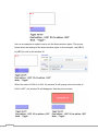
Step 1
Set up a window which is intended as a keypad and open it. For example, set
WINDOW 200 as the window for a keypad.
Step 2
Adjust the height and width of WINDOW 200 and on it set up a variety of
objects as Function Keys. Different input signals will be made by pressing
different Function Key objects.
The Function Key objects on WINDOW 200 are arranged as shown in the
picture above. It is a must to select [ASCII mode] to set up all of the Function
Key objects. Among the objects, the FK_11 is used as the “Escape (Esc)” key.
See the picture below for the setting.
And the FK_12 is used as the “ENTER” key. See the picture below for the
setting.
106
Most of the other Function Keys are used to input numbers or text. For
example, the FK_0 is used to input the number “0”. See the picture below for
the setting.
At last, select a proper Picture for each Function Key object, as shown in the
picture below.
Step 3
Go to [General] tab in “System Parameter Settings” and click [Add…] in
[Keyboard], a setting dialog box, as shown in the picture below, will be
displayed, and then select WINDOW 200 and press “OK”.
As shown in the picture below, a new item: “200.Keyboard” will be added to
[Keyboard] in [General] tab in “System Parameter Settings.”
107
After completing all the steps described above, when users open the setting
window of “Numeric Input” or “ASCII Input,” “200.Keyboard” can be found to
add to [Window no] in [Keyboard] setting tab, as shown in the picture below.
[Popup Position] can be used to set the displaying position of the keypad, and
in this function, the EB8000 divides the screen into 9 areas. The top left-hand
corner of the keypad will be placed in the top left-hand corner of the selected
area.
After selecting “200.Keyboard,” when users press “Numeric Input” or “ASCII
Input” objects, WINDOW 200 will pop up on the MT8000 screen. See the
picture below, clicking the Function Key objects on the created keypad means
the same thing of inputting information by using a physical keyboard.
108
Chapter 13
Object
This chapter is to illustrate the ways of using and setting all kinds of objects,
and information other than that provided in this chapter can be found in the
chapter of “Object’s General Attributes” chapter.
Bit Lamp Object
Bit Lamp object displays the ON and OFF states of a designated bit address. If
the bit state is OFF, the State 0 shape will be displayed. If the bit state is ON,
the State 1 shape will be displayed
Click the “bit lamp” icon on the toolbar and the “Bit Lamp Object’s Properties”
dialogue box will appear, then press the OK button after correctly setting each
item on the “General” tab, and a new bit lamp object will be created. See the
pictures below.
109
[Description]
A reference name (not displayed) that you assign to the Bit Lamp.
[PLC name]
Select the PLC that you want to operate.
Read address
The PLC’s register address that controls the Bit Lamp object’s states.
110
[Signal inverse]
Inverse displaying of present states; for example, in fact the present state is
“OFF”, but the object displays the “ON” shape.
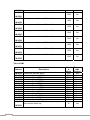
Blinking
The settings of blinking effect.
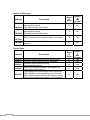
[Mode]
Blinking mode
Description
Normal
The Bit Lamp is displayed as the state of its
shape/bitmap and /or labels.
Blinking on state 0
Enable the shape’s blinking to alternate
between state 0 and state 1 when the
device address is OFF.
Blinking on state 1
Enable the shape’s blinking to alternate
between state 0 and state 1 when the
device address is ON.
Blinking on state 0 (use state 0’s
The shape of state 0 blinks when the device
address is OFF.
graph)
Blinking on state 1 (use state 1’s The shape of state 1 blinks when the device
address is ON.
graph)
When select the blinking effect, [Blinking time] is used to set the frequency of
blinking.
111
Word Lamp Object
A Word Lamp object changes the state and shows the corresponding shape
according to the value in the designated word address. (The EB8000 supports
a maximum of 256 states)
Click the “Word lamp” icon on the toolbar and the “Word Lamp Object’s
Properties” dialogue box will appear, then press the OK button after correctly
setting each item on the “General” tab, and a new word lamp object will be
created. See the pictures below.
112
[Mode]
Word lamp object offers the following three modes for selection:
a.
“Value” display mode
Directly using the result of the value of register subtracting the setting
number of [Offset] as the object’s current state. For example, add a
new word lamp object, and the object’s [Offset] number is 3. Refer to
the picture below for related settings.
113
Therefore, if the value of [LW200] is 5, the state will show as 2 (= 5-3).
See the picture below.
b.
“LSB” display mode
In this mode, the value of the register will transfer to binary system first,
and then the lowest bit other than value 0 will decide the current state.
The following table shows an example of the register [LW200]:
Decimal
Binary
Displayed State
System
System
0
0000
All bits are 0, displaying the state 0
1
0001
The lowest bit other than 0 is bit 0,
displaying the state 1
2
114
0010
The lowest bit other than 0 is bit 1,
displaying the state 2
3
0011
The lowest bit other than 0 is bit 0,
displaying the state 1
4
0100
The lowest bit other than 0 is bit 2,
displaying the state 3
7
0111
The lowest bit other than 0 is bit 0,
displaying the state 1
8
1000
The lowest bit other than 0 is bit 3,
displaying the state 4
c.
“Auto changed” display mode
The states of the object have nothing to do with the register. The object
will change the states according to the fixed frequency. Users can use
[Change time] to set the frequency.
Read address
The PLC’s register address that controls the Word Lamp object’s states.
Attribute
115
[State no.]
The number of the object’s states. The state’s serial number begins from 0, so
the maximum state that can be showed is [State no.] - 1. Supposed that the
number of the state is 8, and the states will be showed as 0, 1, 2,…, 7 in order.
When the current state is beyond [State no.] - 1, the EB8000 will show the last
state.
Set Bit Object
The Set Bit object provides two operation modes: the “manual operation” mode
and the “automatic operation” mode. The Set Bit object can be used to define a
touching area, and users can activate the area to set the state of the
designated register to be ON or OFF.
When users select the “automatic operation” mode, the object’s defined action
will be automatically activated in some particular conditions. In the “automatic
operation” mode, the object will not have any when the object’s touching area
is pressed.
Click the “Set Bit” icon on the toolbar and the “New Set Bit Object” dialogue
box will appear, then press the OK button after correctly setting each item on
the “General” tab, and a new Set Bit object will be created. See the pictures
below.
116
Write address
The PLC’s register address that controls the Set Bit object’s states.
[Write when release this button]
When this function is selected, the object’s defined action will be performed
only after the
pressing motion on the button is released completely. When
the function is not selected, the object’s defined action will be performed as
soon as the touching area of the object is pressed. But when the “Momentary”
switch is selected for the operation mode, the [Write when release this button]
function will be disabled.
Attribute
117
[Switch Style]
To set the operation mode. The available modes for selection are listed as
follows:
Set ON
In this mode, when the object is pressed, the state
of the designated register will be set to ON.
Set OFF
In this mode, when the object is pressed, the state
of the designated register will be set to OFF.
Toggle
In this mode, when the object is pressed, the state
of the designated register will be set to the
opposite, (i.e. ON Æ OFF or OFF Æ ON.
Momentary
In this mode, when the object is pressed, the state
of the designated register will be set to the
opposite; however, when the pressing motion
stops, the state will resume as it was.
Periodical toggle
In this mode, the state of the designated register
will
be
switched
between
ON
and
OFF
periodically. Manual operation is not available in
the mode, but operation’s time interval can be
selected in the combo box showed in the picture
below:
Set ON when open
In this mode, when the window containing the Set
window
Bit object is opened, the designated register will be
automatically set to ON.
118
Set OFF when open
In this mode, when the window containing the Set
window
Bit object I opened, the designated register will be
automatically set to OFF.
Set ON when close
In this mode, when the window containing the Set
window
Bit object is closed, the designated register will be
automatically set to ON.
Set OFF when close
In this mode, when the window containing the Set
window
Bit object I closed, the designated register will be
automatically set to OFF.
119
Set Word Object
The Set Word object provides two operation modes: the “manual operation”
mode and the “automatic operation” mode. The Set Word object can be used
to define a touching area, and users can activate the area to set the value of
the designated register.
When users select the “automatic operation” mode, the object’s defined action
will be automatically activated in some particular conditions. In the “automatic
operation” mode, the object will not have any when the object’s touching area
is pressed.
Click the “Set Word” icon on the toolbar and the “New Set Word Object”
dialogue box will appear, then press the OK button after correctly setting each
item on the “General” tab, and a new Set Word object will be created. See the
pictures below.
120
Write address
The PLC’s register address that controls the Set Word object’s states.
[Write when release this button]
When this function is selected, the object’s defined action will be performed
only after the
pressing motion on the object is released completely. When
the function is not selected, the object’s defined action will be performed as
soon as the object is pressed.
Notification
121
When this function is selected, in the “manual operation” mode, the state of the
designated register can be set at the same time as the operation is completed.
There are [ON] and [OFF] for selection to set the state.
[Enable]
This is for selecting whether or not to use the function.
[Before writing]
To set the state of the designated register before writing.
[After writing]
To set the state of the designated register after writing.
Attribute
[Mode]
To set the operation mode. The available modes for selection are listed as
follows:
122
a. “Set const”
Constant setting function. Whenever the object is pressed, the value
set in [Set value] will be written into the designated register. The
constant’s style (16-bit BCD, 32-bit BCD, …) can be decided in “Write
address”.
b. “Add value(JOG+)”
Value adding function. Whenever the object is pressed, the value set
in [Inc. value] will be added to the value of the designated register, but
the resulting value will not be larger than the value in [Upper limit].
c. “Sub value(JOG-)”
Value subtracting function. Whenever the object is pressed, the value
set in [Dec. value] will be subtracted from the value of the designated
register, but the resulting value will not be smaller than the value in
[Bottom limit].
123
d. “JOG++”
Increasing function. When the time of the object being pressed is
longer than the time set in [JOG delay], the value of the designated
register will be added by the value set in [Inc. value] at the speed set in
[JOG speed], but the resulting value will not be larger than the value in
[Upper limit].
e. “JOG--”
Decreasing function. When the time of the object being pressed is
longer than the time set in [JOG delay], the value of the designated
register will be subtracted by the value set in [Dec. value] at the speed
set in [JOG speed], but the resulting value will not be smaller than the
value in [Bottom limit].
f. “Periodical JOG++”
124
Periodically increasing function. A set word object can use the interval
set in [Break time] and the value set in [Inc. value] to automatically
increase the value of the designated register, but the resulting value
will not be larger than the value in [Upper limit].
g. “Periodical JOG--”
Periodically decreasing function. A set word object can use the interval
set in [Break time] and the value set in [Dec. value] to automatically
increase the value of the designated register, but the resulting value
will not be smaller than the value in [Bottom limit].
h. “Periodical bounce”
Periodically bouncing function. A Set word object will add the value set
in [Inc. value] to the value of the designated register at the regular
intervals set in [Break time] until the resulting value reaches the value
in the [Upper limit], and then subtract the value set in [Inc. value] from
125
the value of the designated register at the same intervals until the
resulting value reaches the value in the [Bottom limit]. In the example
showed in the picture below, the value in the designated register will
change periodically in order of 0, 1, 2.., 9, 10, 9, 8, 7,…, 1, 0, 1, 2……
i. “Step up”
Stepping up function. A Set word object will add the value set in [Inc.
value] to the value of the designated register at the regular intervals
set in [Break time] until the resulting value reaches the value in the
[Upper limit], and the value of the designated register will return to the
value in the [Bottom value] and then repeat the action to keep the
value in an active state. In the example showed in the picture below,
the value in the designated register will change periodically in order of
0, 1, 2,…, 9, 10, 0, 1, 2, ……
j. “Step down”
126
Stepping down function. A Set word object will subtract the value set in
[Dec. value] from the value of the designated register at the regular
intervals set in [Break time] until the resulting value reaches the value
in the [Bottom limit], and the value of the designated register will return
to the value in the [Upper value] and then repeat the action to keep the
value in an active state. In the example showed in the picture below,
the value in the designated register will change periodically in order of
10, 9, 8,…, 1, 0, 10, 9, 8, ……
k. “Set when open window”
When the window containing the object is opened, the value set in [Set
value] will be automatically written into the designated register.
l. “Set when close window”
When the window containing the object is closed, the value set in [Set
value] will be automatically written into the designated register.
127
Function Key Object
Function key object is used to change windows, call up windows and minimize
or close windows. It can also be used to design the keypad buttons. Click the
“Function Key” icon on the toolbar and the “Function Key Object’s Properties”
dialogue box will appear, then press the OK button after correctly setting each
item in the “General” tab, and a new function key object will be created. See
the pictures below.
128
Function Key object provides the following operation modes:
[Activate command when release this button]
When the function is selected, the defined action will be performed only when
the pressed the object is released completely. When the function is not
selected, the defined action, for example, changing windows, will be performed
immediately when the object is pressed.
129
[Change window]
Change base window.
[Change common window]
Change common window; refer to the “windows” chapter for related
information.
[Popup window]
Calling up other windows. The called-up window must be upper than the base
window. The [Close when change window] function is available in this function,
see the picture below; when the function is selected, the called-up window will
disappear when changing window. Otherwise, users have to set a “Close”
button on the called-up window to close the window.
[Window no.]
This is used to select the window no. when performing “change base window”,
“change common window”, and “call up other window”
[Return previous]
This is used to return to the previous base window. Fox example, when
changing window 10 to window 20, users can use this function to return to
window 10. This function is only available to base window.
130
[Close window]
Closing the called-up windows in the base window, including information
windows and so on.
Items in ASCII mode
[ASCII mode] is used as input signals of keypad, mainly in occasions when
numbers or text are needed to key in from the keypad for a numeric input
object or an ASCII input object is in need is required for keypad input. Refer to
the “Designing and Using Keypad” chapter for detailed information.
[Enter]
Same as the keyboard’s “enter” fuction.
[Backspace]
Same as the keyboard’s “backspace” fuction.
[Clear]
To clear the input data in the current numeric input object or ASCII input
object.
131
[Esc]
Same as the [Close window] function. Both can be used to close the called-up
keypad window.
[ASCII]
To set the characters that are input in the numeric input object and the ASCII
input object. Digital characters such as 0,1,2… or ASCII characters like
a,b,c,… etc. are available for selection.
Notification
[Enable]
When the function is selected, the EB8000 will set the stated of the designated
register after the action is completed. Use [ON] and [OFF] to select the state.
Toggle Switch Object
Toggle Switch object is a combination of bit lame object and set bit object. The
object can be used not only to display the state of a register but also to define a
touching area, and when the area is pressed, the state of the designed register
will be set to “ON” or “OFF”. Click the “Toggle Switch” icon on the toolbar and
the “New Toggle Switch Object” dialogue box will appear, then press the OK
button after correctly setting each item in the “General” tab, and a new toggle
switch object will be created. See the pictures below.
132
Read address
The PLC’s register address that controls the Toggle Switch object’s states.
Write address
The PLC’s register address that is controlled by the Toggle Switch object’s
states. The register can be the same as or different from the register
designated by the “Read address”
[Write when release this button]
133
Refer to the “Set Bit Object” section of this chapter for related information.
Attribute
This is used to select the operation mode. Available modes for selection
include “Set ON”, “Set OFF”, ”Toggle”, and ”Momentary”. Refer to the
illustrations in the “Set Bit Object” section of this chapter for related
information.
Multi-Switch Object
Multi-State Switch object is a combination of word lamp object and set word
object. The object can be used not only to display the state of a register
according to the value but also to define a touching area in the window, and
the value of the designed register can be set when the area is pressed.
Click the “Multi-State Switch” icon on the toolbar and the “New Multi-State
Switch Object” dialogue box will appear, then press the OK button after
correctly setting each item in the “General” tab, and a new Multi-State Switch
object will be created. See the pictures below.
134
[Mode]
To provide “Value” and “LSB” display mode. Refer to the “Word Lamp Object”
section of this chapter for related information.
[Offset]
It is used in the “Value” display mode. Refer to the “Word Lamp Object” section
of this chapter for related information.
Read address
135
The PLC’s register address that controls the Multi-State Switch object’s states.
Write address
The PLC’s register address that is controlled by the Multi-State Switch object’s
states. The register can be the same as or different from the register
designated by the “Read address”
[Write when release this button]
Refer to the “Set Bit Object” section of this chapter for related information.
Attribute
To select the object’s operation mode.
[Switch style]
There are “JOG+” and “JOG-” for selection. When the read address is the
same as the write address, the minimum value of the designated register is
[Offset](the current state is 0), and the maximum value is ([State no.] -1) +
[Offset] (the current state is [State no.] -1). See the picture below.
136
a. “JOG+”
Whenever the Multi-State Switch object is pressed, the value of the
designated write address will be added by 1. In the “Value” display
mode, if the resulting value is equal to or larger than the value of [State
no.] + [Offset] and “Enable” in [Cyclic] is selected, the value of the
register will return to [Offset] and show the state 0; otherwise the value
of the register will maintain as ([State no.] – 1) + [Offset] and show the
state ([State no.] – 1).
Note: Like the word lamp object, the state showed by Multi-State
Switch object is the value of the designated register that subtracts
[Offset].
b. “JOG-”
Whenever the Multi-State Switch object is pressed, the value of the
register designated in “write address” will be subtracted by 1. In the
“Value” display mode, if the resulting value is smaller than the value of
[Offset] and “Enable” in [Cyclic] is selected, the value of the register
will change to ([State no.] – 1) + [Offset] and show the state ([State
no.] – 1); otherwise the value of the register will maintain as [Offset]
and show the state 0.
137
Numeric Input and Numeric Display Objects
Both of the Numeric Input object and the numeric display object can be used to
display the value of the designated register. Besides, the numeric input object
can also use the value input by the keypad to change the value of the
designated register.
Click the “numeric input” or “numeric display” icon on the toolbar and the “New
Numeric Input Object” or “New Numeric Display Object” dialogue box will
appear, then press the OK button after correctly setting each item in the
“General” tab, and a new “Numeric Input Object” or “Numeric Display Object”
will be created. See the pictures below.
The difference between the “New Numeric Input Object” and “New Numeric
Display Object” dialogue boxes is that the latter has the settings
for ”Notification” and keypad input while the former doesn’t have. The picture
below shows the [General] tab in “New Numeric Display Object.”
138
Read address
The PLC’s register address that controls the Numeric Input object’s (or the
numeric display object’s) states.
Notification
When the settings in “Notification” are used, it is able to set the state of the
designated register, using [ON] and [OFF] to select the state, after the value of
the register is changed successfully (the input value must be limited to the
defined range, refer to the “Numeric Format” section for related information.).
139
[Enable]
To decide whether or not to use the function.
[Before writing]
To set the state of the designated register before the value of the register is
changed.
[After writing]
To set the state of the designated register after the value of the register is
changed.
Keyboard
When using the Numeric Input Object, users are allowed to select the keypad
style. Users need to select the window where the keypad will be displayed and
set the displaying position of the keypad. When the Numeric Input object is
touched, the keypad will appear automatically. Refer to the “Designing and
Using Keypad” chapter for further information.
140
The picture below shows the [Numeric Format] tab, included in both of the
numeric input object and the numeric display object, for setting the data
display mode.
[Data format]
To select the data format type of the PLC’s register designated by the “Read
address”. The available types for selection are listed as follows:
141
[Mask]
When the data is displayed, “*” will be used to replace all digitals and the color
warning function will be cancelled.
[No. above dec.]
The number of places before the decimal point.
[No. below dec.]
The number of places after the decimal point.
[Raw data display]
To display the raw data of the PLC’s register designated by the “Read
address”.
[Do conversion]
The displayed data is the result of processing the raw data of the PLC’s
register designated by the “Read address.” When the function is selected, it is
necessary to set [Engineering low], [Engineering high], and [Input low] and
[Input high] in the “Limitation”. Supposed that “A” represents the raw data and
“B” represents the displayed data, and the converting formula expression can
be:
142
B = [Engineering low] + (A - [Input low]) * ratio
In above, the ratio = ([Engineering high] - [Engineering low]) / ([Input
high] - [Input low])
See the example in the picture below, the raw data is 15, after being converted
by the above formula as 10 + (15 – 0) * (50 – 10) / (20 - 0) = 40, and 40 of the
resulting data will be displayed on the numeric input object.
Limitation
To set the source of the range for the input data and to set the warning color
effect.
[Direct]
The low limit and high limit of the input data can be set in [Input low] and [Input
high] respectively. If the input data is out of the defined range, it is not able to
change the value of PLC’s register designated by the “Read address”.
143
[Limit from PLC]
Set the low limit and high limit of the input data to be sourced from the
designated register. The data length of the designated register is related to the
object’s data displaying type. In the above example, the low limit and high limit
are sourced from [LW100] and the following explains the addresses of the low
limit and high limit.
a. If the displayed data’s format type is “32-bitBCD”, then
[LW100]
low limit position (32-bit BCD)
[LW100 + 2]
high limit position (32-bit BCD)
b. If the displayed data’s format type is “16-bit unsigned”, then
[LW100]
low limit position (16-bit unsigned)
[LW100 + 1]
high limit position (16-bit unsigned)
c. If the displayed data’s format type is “32-bitfloat”, then
[LW100]
low limit position (32-bit float)
[LW100 + 2]
high limit position (32-bit float)
[Low limit]
When the value of the PLC’s register is smaller than [Low limit], the object will
display data in the defined color.
144
[High limit]
When the value of the PLC’s register is larger than [High limit], the object will
display data in the defined color.
[Blink]
When the value of the PLC’s register is smaller than [Low limit] or larger than
[High limit], the object will use the Blink effect as warning. The picture below
shows the [Font] tab, available in both of the numeric input object and the
numeric display object, for setting the data’s displaying font, font size and color,
and aligning mode.
[Color]
When the data is in the defined range, they will be displayed in the defined
color.
[Align]
There are three aligning modes: “Left”, “Leading zero”, and “Right”. The picture
below shows how each mode performs.
145
ASCII Input and ASCII Display Objects
Both of the ASCII input object and the ASCII display object can display the
value of the designated PLC register in the ASCII mode. Besides, the ASCII
input object can also use the value input by the keypad to change the value of
the designated PLC register.
Click the “ASCII Input” or “ASCII Display” icon on the toolbar and the “New
ASCII Input Object” or “New ASCII Display Object” dialogue box will appear,
then press the OK button after correctly setting each item in the “General” tab,
and a new “ASCII Input Object” or “ASCII Display Object” will be creased. See
the pictures below.
The difference between the “New ASCII Input Object” and “New ASCII Display
Object” dialogue boxes is that the latter has the settings for “Notification” and
keypad input while the former doesn’t have. The picture below shows the
[General] tab in the “New ASCII Input Object.”
146
Read address
The PLC’s register address that is displayed and modified by the ASCII Input.
[No. of words]
To set the maximum of displayed data length; the unit is word and the
minimum length can be set for 1. Because the length of each ASCII character
is one byte, it will display 2 characters at least every time. In the example
shown in the pictures below, the object can display 3 * 2 = 6 characters the
most.
147
Notification
Refer to the “numeric input” section of this chapter for related information.
Keyboard
Refer to the “numeric input” section of this chapter for related information.
The picture shows the [Font] tab of the ASCII Input object and the ASCII
display object. Users can set the data’s displaying font, font size and color, and
aligning mode.
[Align]
There are two aligning modes: “Left” and “Right”. The picture below shows
how each mode performs.
148
Indirect Window Object
Indirect window Object can define a display area in a window, and after the
definition of a register is completed and when the value of the designated
register is the same as the number of the defined window, the window will
popup in the defined display area. The size of the popup window will not be
larger than the display area. The popup window can be closed when the value
of the designated register is set for 0.
Click the “indirect window” icon on the toolbar and the “New Indirect
Window Object” dialogue box will appear, the press the OK button after
correctly setting each item in the “General” tab, and a new “Indirect Window
Object” will be created. See the pictures below.
149
Read address
To set the register as the source for the window’s number.
Attribute
[Style]
To set the displaying style of the popup window. There are two styles, “No
drawing frame” and “Drawing frame” for selection.
a. “No drawing frame”
The popup window does not have title bar, and its position is not
movable.
150
b. “Drawing frame”
The Popup window possesses title bar, and its position is movable.
Here is a simple example to explain how to use the indirect window object. The
pictures below show how to set the indirect window object. Use the register
[LW100] to appoint the number of the window which is going to popup, and the
window 35 and window 36 must have been created first.
151
Use the set word object SW_0 and set the value of [LW100] to 35, and the
display will be like the picture below.
If continue to use the set word object SW_1 and set the value of [LW100] to 36,
the window 35 will be closed and the window 36 will be popped up. See the
picture below.
152
If want to close window 35 or window 36, besides using the set word object
SW_2 to set the value of [LW100] to 0, users can set a function key object on
window 35 and window 36 and select the [Close window] mode, and the popup
window can be closed when pressing the object.
153
Direct Window Object
Direct window Object can be used to define a display area in a window, when
the state of the designated register is changed from OFF to ON, the
designated window will popup in the display area. The size of the popup
window will not be larger than the display area. The popup window can be
closed when the state of the designated register is changed from ON to OFF.
The difference between the “Direct window” and the “Indirect window” is that
the direct window object sets the popup window in advance. When system is in
operation, users can use the state of the designated register to decide whether
to popup the window or to close the window.
Click the “Direct window” icon on the toolbar and the “New Direct
Window Object” dialogue box will appear, then press the OK button after
correctly setting each item in the “General tab, and a new “Direct Window
Object” will be created. See the pictures below.
154
Read address
When the designated register’s state is ON, the selected window (It is window
35 in the picture above) will be displayed in the defined area. When the state is
OFF, the window will be closed.
Attribute
[Style]
Refer to the “Indirect Window Object” section of this chapter for related
information.
[Window no.]
To set the popup window number.
155
Here is an example to explain how to use the direct window object. The picture
below show the settings of the direct window object. In the example, use [LB10]
to [LB10] to call up the window 35.
When the state of LB10 is to ON, the window 35 will popup; when the state of
LB10 is OFF, the window 35 will disappear. See the picture below.
156
Moving Shape Object
Moving Shape object is used to define the object’s state and moving distance.
Click the “Moving Shape” icon on the toolbar and “New Moving Shape Object”
dialogue box will appear, then press the OK button after correctly setting each
item in the “General” tab, and a new “Moving Shape Object” will be created.
See the pictures below.
157
Read address
The PLC’s register address that controls the object’s state and moving
distance. The table below shows the read address of object’s states and
moving distance.
Data format
Read address of
Read address of
Read address of
object’s state
Moving Distance
Moving distance
on the X-axis
on the Y-axis
16-bit BCD
Address
Address + 1
Address + 2
32-bit BCD
Address
Address + 2
Address + 4
16-bit
Address
Address + 1
Address + 2
16-bit Signed
Address
Address + 1
Address + 2
32-bit
Address
Address + 2
Address + 4
Address
Address + 2
Address + 4
Unsigned
Unsigned
32-bit Signed
For example, if the register’s address is [LW100] and the data format is “16-bit
Unsigned”, [LW100] is to save the object’s state, [LW101] is to save the
object’s moving distance on the X-axis, and [LW102] is to save the object’s
moving distance on the Y-axis.
The picture below shows that the object’s read address is [LW100] and initial
position is (100, 50). Supposed that the object is moved to the position (160,
158
180) and display the shape of State 2, the value of [LW100] must be set to 2,
[LW101] = 160-100 = 60, [LW102] = 180-50 = 130.
Attribute
To select the object’s moving mode and range.
a. X axis only
The object is only allowed to move along the X-axis. The moving range
is defined by [Min. X] and [Max. X].
159
b. Y axis only
The object is only allowed to move along the Y-axis. The moving range
is defined by [Min. Y] and [Max. Y].
c. X & Y axis
The object is allowed to move along the X-axis and Y-axis. The moving
range is defined by [Min. X], [Max. X] and [Min. Y], [Max. Y]
d. X axis w/ scaling
The object is only allowed to move by the designated scale along the
horizontal X-axis. Supposed that the value of the designated register is
DATA, and the following formula can calculate the moving distance on
the X-axis.
X axis move distance =
(DATA – [Input low]) * ([Scaling high – Scaling low]) / ([Input high] –
[input low])
160
For example, the object is only allowed to move within 0~600, but the
range of the register’s value is 300~1000, set [Input low] to 300 and
[Input high] to 1000, and set [Scaling low] to 0 and [Scaling high] to
600, and the object will move in the designated range.
e. Y axis w/ scaling
The object is only allowed to move by the designated scale along the
vertical Y-axis., and the formula to calculate the moving distance on
the Y-axis is the same as the one in “X axis w/ scaling.”
f. X axis w/ reverse scaling
This function is the same as “X axis w/ scaling”, but the moving
direction is reverse.
g. Y axis w/ reverse scaling
This function is the same as “Y axis w/ scaling”, but the moving
direction is reverse.
Display ratio
The displaying size of object’s shape in different states can be set individually
as shown in the picture below.
161
Limit address
The object’s displaying range can be set not only by [Min. X], [Max. X] and [Min.
Y] [Max. Y], but also by the designated register. Supposed that the object’s
displaying range is set by the value of the designated register “Address”, the
reading address of [Min. X], [Max. X] and [Min. Y] [Max. Y] are listed in the
following table.
Data format
[Min. X]
[Max. X]
[Min. Y]
[Max. Y]
read address
read address
read address
read address
16-bit BCD
Address
Address + 1
Address + 2
Address + 3
32-bit BCD
Address
Address + 2
Address + 4
Address + 6
16-bit
Address
Address + 1
Address + 2
Address + 3
16-bit Signed
Address
Address + 1
Address + 2
Address + 3
32-bit
Address
Address + 2
Address + 4
Address + 6
Address
Address + 2
Address + 4
Address + 6
Unsigned
Unsigned
32-bit Signed
162
Animation Object
Users can define a moving path of the Animation Object in advance, and
control the object’s state and position on the moving path by changing the
value of the designated register.
Click the “Animation” icon on the toolbar, and click the left button of the mouse
at the proper position in the editing window to define a new moving position.
When definitions of all moving positions are completed, click the right button of
the mouse, and a new animation object and a moving path will be created. See
the picture below.
When wanting to change the object’s attributes, double click the left button of
the mouse on the object, and the “Animation Object’s Properties” dialogue box,
as shown in the picture below, will appear for users to change the object’s
attributes.
163
Attribute
[State no.]
To set the number of the object’s states.
[Position]
When select “Controlled by register”, the designated register controls the
object’s state and position.
164
Read address
If the designated register controls the object’s state and position, it is
necessary to set the read address correctly. In the table below, Address
represents the read address, when the register is [LW100], Address is 100.
Data Format
Read address of object’s Read address of object’s
state
position
16-bit BCD
Address
Address + 1
32-bit BCD
Address
Address + 2
16-bit Unsigned
Address
Address + 1
16-bit Signed
Address
Address + 1
32-bit Unsigned
Address
Address + 2
32-bit Signed
Address
Address + 2
For example, if the designated register is [LW100] and the data format
is ”16-bit Unsigned”, then [LW100] is to save the object’s state, [LW101] is to
save the object’s displaying position. In the picture below, [LW100] = 2,
[LW101] = 3, so the object’s displaying state is 2 and displaying position is 3.
165
If “Controlled by register” is not selected, the object will change the state and
displaying position automatically. “Position auto changed” is used to set the
change mode of state and displaying position.
[Speed]
Position changes speed, the unit is 0.1 second. Supposed that [Speed] is set
to 10, the object will change its position every 1 second.
[Backward]
Supposed that the object has four positions: position 0, position 1, position 2,
and position 3. If [Backward] is not selected, when the object moves to the last
position (position 3), next position will be back to the initial position 0, and
166
repeat the moving mode again and again. The moving path is shown as
follows:
position 0-> position 1->position 2->position 3-> position 0-> position 1->
position 2…
If [Backward] is selected, when the object moves to the last position (position
3), it will move backwards to the initial position 0, and repeat the moving mode
again and again. The moving path is shown as follows.
position 0-> position 1->position 2->position 3-> position 2-> position 1->
position 0…
[State changed]
State’s changing mode. There are “Position dependant” and “Auto changed”
for selection. When “Position dependant” is selected, it means that following
the change of position, the state will change too. When “Auto change” is
selected, it means that the position will change automatically in a fixed
frequency, and the changing frequency can be set in [Update time].
167
Shape rectangle size
To set the size of object’s displaying shape.
Trajectory
To set the position of each point on the moving path.
168
Bar Graph Object
Bar graph object displays PLC register data as a bar graph in proportion to its
value. Click the “Bar Graph” icon on the toolbar, there will appear “Bar Graph”
dialogue box, press OK button after correctly fill in the General Attribute, there
will be a new “Bar Graph Object”. See the picture below.
The following picture shows the “General” tab of the bar graph object.
Read address
PLC’s register address that controls the bar graph display.
169
The following picture shows the “Outline” tab of the bar graph object.
Attribute
[Direction]
To select the bar’s displaying direction, and there are ”Up”, “Down”, “Right”,
and “Left” for selection.
170
[Zero]、[Span]
The filled bar percentage can be calculated with the following formula:
The filled bar percentage = (Register value – Zero)/ [Span] – [Zero])
*100%
Bar color/style
To set the bar’s Frame, Background color, Bar style, and Bar color. See the
picture below.
Destination
When the register value meets the following condition, the filled area’s color of
the bar will change to the “Destination color”
[Desti. Value] - [Tolerance] < = Register value < = [Desti. Value] +
[Tolerance]
171
See the picture below, in here [Desti. Value] = 5, [Tolerance] = 1, if the register
value is equal to or larger than 5-1=4 and equal to or less than 5+1=6, the filled
area’s color of the bar will change to the “Destination color”
Limitation alarm
When register’s value is larger than [High limit], the filled area’s color of the bar
will change to [High color], when register’s value is smaller than [Low limit], the
filled area’s color of the bar will change to [Low color].
Limit/Destination address
When select [Limit/destination from register], the [Low limit] and [High limit] of
“Limitation alarm” and the [Desti. Value] of “Destination” all come from
designated register. See the picture below.
172
The following table shows the read address of low limit, high limit, and
destination. The “Address” means the register’s address, for example, if the
register is [LW100], the “Address” is 100.
Data Format
Low limit
High limit
Destination
16-bit BCD
Address
Address + 1
Address + 2
32-bit BCD
Address
Address + 2
Address + 4
16-bit
Address
Address + 1
Address + 2
16-bit Signed
Address
Address + 1
Address + 2
32-bit
Address
Address + 2
Address + 4
Address
Address + 2
Address + 4
Unsigned
Unsigned
32-bit Signed
173
Meter Display Object
The meter display object can displays the PLC register’s data by using meter
in proportion. Click the “Meter Display” icon on the toolbar and the “Meter
Display Object’s Properties” dialogue box will appear, then press the OK
button after correctly setting each item in the “General” tab, and a new “Meter
Display Object” will be created. See the picture below.
The picture below shows the “General” tab in the “Meter Display Object’s
Properties” dialogue box.
174
Read address
PLC’s register address that control the displayed value.
In the above dialogue box, users can set the meter display object’s outline.
Refer to the picture below for the names of each part of the meter.
175
Degree
Set the object’s “start degree” and “end degree”, the angle range is 0-360
degrees. The following pictures show several results of different settings.
[Start degree] = 290, [End degree] = 70
[Start degree] = 45, [End degree] = 240
176
[Start degree] = 120, [End degree] = 135
[Start degree] = 225, [End degree] = 315
Background
Set the object’s background color and profile color.
[Full circle]
When the “Full circle” is selected, the object will display the whole circle,
otherwise the object will display the defined degree range. See the picture
below.
177
[Transparent]
When the “Transparent” is selected, the object will not display the background
and profile color. See the picture below.
Tick marks
To set the tick mark’s number and color.
178
Pointer
To set Pointer’s style, length, width, and color.
Pin point
To set pin point’s style, radius, and color
The following pictures show the “Limit” tab and the sign of low and high limit
set in the “Limit” tab.
179
Value
To set object’s displaying range. Meter display object will use the value of
[Zero] and [Span] and the value of register to calculate the pointer’s indication
position. For example, supposed that [Zero] = 0, [Span] = 100, when the value
of register is 30 and [Start degree] = 0, [End degree] = 360, then the degree
indicated by pointer is:
{(30 – [Zero])/([Span] – [Zero])} * ([[End degree] - [Start degree]] =
{(30 – 0) / (100 - 0)} * (360 – 0) = 108
Pointer will indicate the position of 108 degrees. See the picture below.
180
Range
To set the value of low and high limit and the displaying color and width of the
sign of low and high limit.
[Display range mark]
Whether or not to display the range mark.
[Low/ high limits from register]
When “Low/ high limits from register” is not selected, the low limit and high limit
are a fixed value, which directly comes from settings. See the example in the
picture below, the low limit is 30 and high limit is 60.
If “Low/ high limits from register” is selected, the register value controls the low
limit and high limit. See the picture below.
181
There following table shows the read address of low limit, high limit. The
“Address” means the register’s address. If the register is [LW100], the
“Address” is 100.
Data format
182
High
limit’s
read Low
limit’s
address
address
16-bit BCD
Address
Address + 1
32-bit BCD
Address
Address + 2
16-bit Unsigned
Address
Address + 1
16-bit Signed
Address
Address + 1
32-bit Unsigned
Address
Address + 2
32-bit Signed
Address
Address + 2
read
Trend Display Object
Trend display object can use the continuous line to describe the data recorded
by data sampling object, so the trend of data changing’s variation can be
showed clearly. The following picture shows the status of using trend display
object.
Click the “Trend Display” icon on the toolbar and the “Trend Display Object’s
Properties” dialogue box will appear, then press the OK button after correctly
setting each item in the “General” tab, and a new “Trend Display Object” will be
created. See the picture below.
183
The following picture shows the “General” tab in the “Trend Display Object’s
Properties” dialogue box.
[Data sampling index]
To select data sampling object as the data source required for graphing. Refer
to the “data sampling” section for related information.
184
[Display mode]
To select the format of data source and there are “Real-time” and “History” for
selection.
a. Real-time
In the mode, it can display the sampling data from the beginning of the
MT8000 operation to the present time. If previous data are required,
users must select the “History” mode to read the data from historical
record.
Users can use the “Hold control” object to pause updating the trend
display, but it is only limited to pausing the updating of the trend
display, and it will never stop the object sampling the data. The picture
below shows the “Hold control” setting page. Set the state of the
designated register to ON, it will pause updating the trend display.
b. History
In the mode, the displayed sampling data come from the historical
record of the designated data sampling object in [Data sampling index].
Data sampling object will use the sampling data that are stored by
sorting according to dates. It is able to use “History control” to select
185
the historical records that are created by the same data sampling
object. The picture below shows the “History control” setting page.
The EB8000 will sort the historical records of sampling data by date;
the latest file is record 0 (normally it is today’s saved sampling data),
the second latest file is record 1, and the rest may be deducted in the
same way.
If the value of designated register in “History control” is 0, the trend
display object will display data of record 0; if the value of designated
register in “History control” is 1, the trend display object will display the
data of record 1; therefore, we can deduce that if the register’s value is
n, the trend display object will display the data of record n.
Here is an example to explain how to use the “History control.” In the
above picture, the designated register is [LW200], if the sampling data
are saved by the current data sampling object in the order of date as
the
files
of
pressure_20061120.dtl,
pressure_20061123.dtl,
pressure_20061127.dtl, and pressure_20061203.dtl, and today’s date
is 2006/12/3, according to the value of [LW200], the sampling data files
186
displayed by the trend display object are arranged in the following
table.
Value of [LW200]
The files of the sampling
data
from
the
historical
record
0
pressure_20061203.dtl
1
pressure_20061127.dtl
2
pressure_20061123.dtl
3
pressure_20061120.dtl
In other words, the smaller the value of [LW200] is, the closer to the
present time the historical record will be.
[Channel no.]
The channel number that the object can display. Each channel means the data
sampling object continue to get the sampling data for one PLC register.
[Pixel]
Select [Pixel], the [Distance] can be used to set the distance between two
sampling points. See the picture below.
187
[Time]
Select [Time], the [Distance] is used to set the time range for the display shape.
See the picture below.
Watch
188
Using the “Watch” function, when user touch the trend display object, object
will display a “watch line”, and can export the sampling data at the position of
watch line to the designated register. See the picture below, export the
sampling data at the position of watch line to [LW300]
“Watch” function also can export several channel sampling data, MT8000
export the sampling data at the position of watch line to the designated register
in turn according to the data format defined by data sampling object. For
example each sampling data include four data format, they are “16-bit
unsigned”, “32-bit unsigned”, “32-bit float”, and “16-bit Signed” respectively.
189
Suppose now the [LW300] is the designated register defined by “Watch”, the
following are the export address of sampling data marked by “watch line”.
[LW300]
Line 0 : 16-bit Unsigned
[LW301]
Line 1 : 32-bit Unsigned
[LW303]
Line 2 : 32-bit Unsigned
[LW305]
Line 3 : 16-bit Signed
( 1 words)
( 2 words)
( 2 words)
( 1 words)
The picture below shows the “trend display” setting page.
190
[Frame]
Object frame’s color.
[Background]
Object background’s color.
Grid
Set the number grid and grid color.
[Display]
Select whether use grid line.
[Horiz.]
Set the number of horizontal line.
[Verti. interval]
When select [pixel] to set the display interval (see note on the above graph and
“General” tab), the [Verti. interval] is used to select how many sampling point
will be included between two vertical grid line. See the picture below.
191
When select [Time] to set the time range of display data, the [Verti. interval] is
used to select the time range between two vertical grid lines. See the picture
below.
According to these settings, MT8000 will calculate the number of vertical grid
line automatically.
Channel
Set each sampling line’s format and color, and the display data’s low limit and
high limit.
[Zero]、[Span]
[Zero] and [Span] are used to set the low limit and high limit of sampling data,
So if the low limit is 50 and high limit is 100 for one sampling line, then [Zero]
and [Span] must be set as [50] and [100], so all the sampling data can be
totally displayed in the trend display object.
Time/Data
The time of latest sampling data will be marked on the top left corner of the
object. It is used to set the time display format and color.
192
Alarm Bar and Alarm Display Objects
Alarm bar and alarm display object are used to display messages registered in
the “event log” when the system current state meets trigger conditions. Here
these messages are also called alarm. Alarm bar and alarm display object
display these alarms in order of triggering time, of which alarm bar object will
display all alarm messages in one line, alarm display object use multi-line to
display alarm messages and each line display one alarm content. The
following pictures show that the same alarm message is displayed in different
object. Refer to the “Event Log” chapter for related information.
alarm bar object
alarm display object
Click the “Alarm bar” icon on the toolbar, there will appear the “Alarm bar”
dialogue box; in the same way, click the “Alarm display” icon on the toolbar,
there will appear the “Alarm display” dialogue box. Press the OK button after
correctly setting in the “General” tab, a new object will be created. See the
pictures below.
193
194
[Category]
Alarm’s “category” can be displayed when it meet its defined range.(“Category”
can be set in “event log”). For example, when the “Category” of alarm bar
object is set as 2~4, then it will be displayed until “Category” equal 2 or 3 or 4’s
alarm. Refer to the “Category” section in “Event Log” chapter for related
information.
[Moving speed]
The display text’s moving speed in alarm bar object.
Sort
Set the alarm display order.
[Time ascending]
Later triggering alarm is arranged the back (or down).
[Time descending]
Later triggering alarm is arranged the front (or up).
Time
[Event trigger time]
Select whether or not to display the trigger time.
195
Date
[Event trigger date]
Select whether or not to display the trigger date.
Set object’s font and color in the “Font” tab. See the picture below.
Event Display Object
Event display object can be used to display messages registered in the “event
log” when the system current state meets trigger conditions. Event display
object display these event messages in order of triggering time. See the
picture below, event display object also allow the display of event trigger,
acknowledge and return to normal times (System state does not meet the
triggering conditions any longer.)
196
Click the “Event Display” icon on the toolbar, there will appear the “Event
Display” dialogue box, press the OK button after correctly setting each item in
the “General” tab, and a new “Event Display Object” will be created. See the
picture below.
[Mode]
Select the event source format, there are “Real-time” and “History” for
selection.
a. Real-time
197
In the mode, it can display the data from the beginning of the MT8000
operation to the present time. If previous data are needed, users must
select “History” mode to read the data from historical record.
b. History
In the mode, the event display object will display the events stored in
the historical record. The EB8000 will save the event history record
and sort it by date. Users can set the “History control” item to select
display record. The picture below shows the “History control” setting
page.
The EB8000 can arrange the history records in order of time, the latest
file record is 0 (normally it is today’s saved record), the second latest
file record is 1. The rest may be deduced in the same way.
198
If the value of designated register in “History control” is 0, event display
object will display the value of record 0; if the value of designated
register in “History control” is 1, event display object will display the
value of record 1, so if the register value is n, it will display the value of
record n.
Here is an example to explain how to use the “History control”. The
designated register in the above picture is [LW100], supposed that the
current historical record are saved in the order of date to the files as
pressure_20061120.dtl,
pressure_20061123.dtl,
pressure_20061127.dtl, and pressure_20061203.dtl, and today’s date
is 2006/12/3, then the following table shows the event display object
displays the historical record according to the value of [LW100].
Value of [LW100]
Displayed Event’s Historical Record
Files
0
EL_20061203.evt
1
EL_20061127. evt
2
EL_20061123. evt
3
EL_20061120. evt
In other words, the smaller the value of [LW100] is, the closer to the
present time the historical record will be.
199
Write address
When the event is confirmed (refer to the following illustrations for detailed
information), the data in “write value” will be exported to the designated
register. The “write value” is set in “event log” item, as shown in the picture
below. Refer to the “Event Log” chapter for related information.
[Category]
Event’s “category” can be displayed when it meet its defined range (“Category”
can be set in “Event log”). For example, when the “Category” of event display
object is set as 2~4, then it will be displayed until “Category” equal to 2 or 3 or
4’s event. Refer to information related to “Category” in the “Event Log” chapter.
200
[Acknowledge style]
Select the “confirm” action, there are “Click” or “Double click” to select. Here
“confirm” action means that the event which has happened and displayed on
the event display object can
be “Clicked” or “Double clicked” by user, after
the “confirm” action, the EB8000 will not only change the event’s color to the
color in ”Notification”, but also export the value of “write address” to the
designated register.
[Max. event no.]
The maximum of displaying event. When the number of displaying events is
larger than maximum, new event will replace the event with lower security
level.
Color
To set the color when the event is in the different states.
[Acknowledge]
To set the color after the event is confirmed.
201
[Return to normal]
To set the event’s displaying color when system state can not meet the trigger
conditions.
[Select box]
When event is selected, set the highlight box color.
[Sequence no.]
Select whether or not to add the sequence no. before the display event. A prior
event uses a smaller sequence number.
Sort
Set the display order.
[Time ascending]
Later triggering event is arranged the back (or down).
[Time descending]
Later triggering event is arranged the front (or up).
Time
[Event trigger time]
Select whether display the trigger time.
[Acknowledge time]
202
Select whether display the “confirm” time.
[Return to normal time]
Select whether display the display event returns to normal time.
Date
[Event trigger date]
Select whether or not to display the trigger date.
If the event just happens, the font and color of display text can be set in the
“Font” tab. See the picture below.
203
Trigger Data Transfer Object
Trigger data transfer object can transfer the value of designated register to
other designated register, user can use the manual button can do the action,
and using the trigger of designated register’s state also can do the action.
Click “Trigger Data Transfer object” icon on the toolbar, there will appear
“Trigger Data Transfer object” dialogue box, then press the OK button after
correctly setting each item in the “General” tab, a new Trigger Data Transfer
object will be created. See the picture below.
204
Source address
Source address for data transfer.
[No. of words]
The number of transfer data and the unit is word.
Destination address
Destination address for data transfer.
Attribute
Set the data transfer mode.
[Mode]
There are “Manual” mode and “Trigger” modes for selection.
a. Manual mode
The object must be pressed manually to perform data transferring
action.
b. Trigger mode
Using the change of the state of designated register to trigger the data
transferring action. Select the proper trigger mode in [Trigger mode],
the trigger mode include:
[ON->OFF]
205
When the register’s state switch from ON to OFF, will trigger data
transfer action.
[OFF->ON]
When the register’s state switch from OFF to ON, will trigger data
transfer action.
[ON<->OFF]
When the register’s state changes, will trigger data transfer action.
The designated register for the trigger mode can be set in [Trigger
address] as shown in the picture below.
206
20. Periodical Data Transfer Object
Periodical data transfer object is the same as trigger data transfer object,
transfer the value of designated register to other designated register. The
difference from trigger data transfer object is, periodical data transfer object
perform data transfer action automatically at a fixed frequency, and can
transfer the data as the unit of bit.
Click “Periodical Data Transfer object” icon on the toolbar, there will appear the
“Periodical Data Transfer object” dialogue box. See the pictures below.
Press the “New…” button after correctly setting each item is the “General” tab,
and a new Periodical Data Transfer object will be created.
Press the “New…” button in the “Periodical Data Transfer Object” dialogue box,
there will appear the ”Periodical Data Transfer object” dialogue box, as shown
207
in the picture below, and set each item’s attribute correctly, and a periodical
data transfer object will be created.
Attribute
[Address type]
Select the data type, there are word type or bit type to select.
[No. of words] or [No. of bits]
When select “Word type” for [address type], the transfer unit is word, set the
transfer number in [No. of words]. See the picture below.
208
When select “Bit type” for [address type], the transfer unit is bit, set the transfer
number in [No. of bits].
[Interval]
Select the transfer frequency, for example, select 3 seconds, the EB8000 will
transfer data to the designated register every 3 seconds.
Source address
Source address for data transfer.
Destination address
Destination address for data transfer.
After completing all settings and pressing the “OK” button, a new periodical
data transfer object will be created and the object’s content can be seen in the
“Periodical Data Transfer” dialogue box. The object will transfer the continuous
15 bit’s data of LB30 address to the LB60 address every 3 seconds.
209
21. PLC Control Object
When the responding control is started up, the PLC Control Object will operate
a particular action. Click the “PLC Control” icon and the “PLC Control Object”
dialogue box, as shown in the picture below, will appear, then press the
“New…” button and the “PLC Control” dialogue box will appear for users to set
the object’s attributes. Press the OK button when all of the settings are
completed and a new PLC control object will be created.
The picture below shows the “PLC Control” dialogue box which is displayed
when pressing the “New…” button.
210
Attribute
[Type of control]
To set the type of control. The available types of control for selection are listed
in the picture below.
a. “Chang window”
211
To change base window. When the value of [Trigger address] is
changed to the number of an effective window, the current window will
be closed and switch to the window designated by the value of [Trigger
address], and the number of the new window will be written to the
specified address. (Refer to the following illustrations for related
information.) For example, supposed that the number of the current
window is 10, and see the object’s settings in the picture below.
When the value of LW0 is changed to 11 due to other value, EB8000
will not only switch the base window to the window 11 but also change
the value of LW1 to 11.
212
When the windows switch successfully, the write address for the
number of the switching to window will relate to [Address] and data
format. The table below shows the read address of the switching from
window’s number and the write address of the switching to window’s
number. “Address” represents the value of the register’s address, for
example, when the register’s address is [LW100], “Address” is 100.
Data Format Read address of the
Write address of the
switching from
switching to
window’s number
window’s number
16-bit BCD
Address
Address + 1
32-bit BCD
Address
Address + 2
16-bit
Address
Address + 1
Address
Address + 1
Address
Address + 2
Address
Address + 2
Unsigned
16-bit
Signed
32-bit
Unsigned
32-bit
Signed
When the state of [LB9017] is set to ON, the switching to window’s
number will not be written to the specified address.
b. “Write data to PLC (current base window)”
When switch to a base window, the base window’s number will be
written to the address designated by [Trigger address]
213
c. “General PLC Control”
The function enables users to use the value of the designated register
to control the data transference between the PLC and the MT8000.
The transference direction includes four types, see the table below:
Data transference
Data transference direction
code
1
Data of PLC’s register ÆMT8000’s RW Register
2
Data of PLC’s register ÆMT8000’s LW Register
3
Recipe Data of MT8000’s RW Æ PLC’s register
4
Recipe Data of MT8000’s LW Æ PLC’s register
When this function is selected, the EB8000 will use the values of the
four registers in row, starting from the address set in [Trigger address],
to define the data transference direction, the data transference volume,
the data sourcing address, and the address of data transference
destination. The table below explains what the value of each register
represents. [Trigger address] is used to indicate the address of PLC’s
register, for example, when [Trigger address] = DM100, it means that
the values of the four registers from DM100 to DM103 are used to
define the content of data transference.
214
Address
Purpose
Description
[Trigger address]
To save the
It represents the type of data
data
transference. As mentioned
transference
above, there are four registers,
code, and to
and this register is used to save
define the data
control type code. When a new
transference
code is written to the register,
direction
the MT8000 will operate the
corresponding transference.
When the transference is
completed, the value of the
register will resume as 0.
[Trigger address]
To save the
+1
data
transference
size, the unit is
word.
[Trigger address]
To save the
The initial data sourcing
+2
slanting value
address in the transference is
of the sourcing
address in data
[Trigger address] + 4 + Slanting
transference
value of the sourcing address
process.
In the example of OMRON
PLC, if [Trigger address] is set
to DM100, and the value of the
[Trigger address] + 2 register,
i.e. DM102, is 5, and the initial
data sourcing address in the
transference is DM109
(109=(100+4) +5).
[Trigger address]
To save the
In the example of OMRON
+3
initial address
PLC, if [Trigger address] is set
of the recipe
to DM100, and the value of the
data register
[Trigger address] + 3 register,
(RW) or the
i.e. DM 103, is “100”,the initial
local data
addresses of the RW and LW in
register (LW)
the transference will be RW100
and LW100 respectively.
215
Here is an example:
Supposed that it is necessary to use the “General PLC Control”
function, we want to transfer the 16-word data of the OMRON PLC,
starting with DM100, to the MT8000’s recipe register, starting with
RW200. The setting steps are described as follows:
i.
Firstly, supposed that we use four registers, starting with DM10,
to control the data transference. Set a PLC control object on
windows of a HMI by selecting “General PLC Control” in the “type
of Control” and setting the read address to DM10.
ii.
Secondly, confirm the size of the processed data and slanting
value of the sourcing address and set DM11 to 16, which means
the size of the transferred data is 16 words, then set DM12 to 86,
which means the data’s sourcing address is DM100 (100 = 10 +
4 + 86), and set DM13 to 200, which means the destination
address is RW200.
iii.
Lastly, according to the data transferring direction, set data
transference code to perform the process of the transference. If
DM10 is set to 1, which means to transfer the data from PLC’s
register to the MT8000’s RW register. If DM10 is set to 3, the
transferring direction is reverse.
216
The rest two transference modes have a similar setting method,
and the only difference is that the MT8000’s RW register is
changed to the local data register (LW).
d. “Back light control (write back)”
When the state of [Trigger address] is from OFF to ON, the MT8000
will turned off the CCFL backlight and the state of [Trigger address] will
be set to OFF. When the CCFL backlight is turned off, users just have
to touch the screen and the CCFL backlight will be turned on again.
e. “Back light control”
When [Trigger address] is from OFF to ON, the MT8000 will turn off
the CCFL backlight, but because of being without the “write back”
function, the state of [Trigger address] will not be set to OFF.
217
Chapter 14
Library
Creating and Using Shape Library and Picture
The EB8000 provides Shape Library and Picture Library functions to add the
visual effects of objects. Each Shpae and Picture includes a maximum of 256
states. The picture below shows how to create Shape Library and Picture
Library.
Refer to Chapter 10 - “Object’s General Attribute” for information about how to
use Shape Library and Picture Library.
1. Creating Shape Library
Shpae is a graph composed of lines, rectangles, circles and other drawing
objects. A complete Shape is likely to be more than one state, and each state
can include two parts: frame and inner. See the picture below.
An object can be set to use alternatively the Shape’s frame or inner, or to use
both at the same time. Click the “Shape Library” button on the toolbar, and the
218
“Shape Library” dialogue box, as shown in the second picture below, will be
display.
[Library]
This is to select the source of a Shape from the Shape Library which has been
added into the current project.
[State]
219
This is to select the state that the existing Shape wants to display. When there
is no Shape of a Graph displayed in the window, it means that the Shape does
not exist or the state of the Shape is not defined yet.
[Select Lib. …]
Click the [Select Lib. ...] button, and the following picture will be displayed for
users to select the Shape Library to add to the current project.
[New Lib. ...]
Click the button, and the following picture will be displayed for users to add a
new empty Shape Library.
220
[Unattach Lib.]
Click the button, and the following picture will be displayed for users to decide
whether or not to delete the Shape Library in [Library] from the current project.
[Delete Shape]
The button is used to delete the selected Shape.
[Rename …]
Click the button, and the following picture will be displayed for users to rename
the selected Shape.
221
[Place …]
This button is used to export the selected Shape to the window in operation.
See the picture below.
Here is an example of adding a Shape with two states to a new Shape Library
to show how to create a new Shape Library and to add a new Shape to it.
Step 1
Click [New Lib. ...] and input the name of the new Shape Library when the
following dialogue box is displayed.
222
Then, a new Shape Library “TEST” will be added to the Shape Library
Manager dialogue box, but at this moment, there are no Shapes in the library.
Step 2
Add a state to the selected Shape. First, using the drawing tools to draw a
graph in the window and select the graph which wants to be added to the
Shape Library.
223
Then, chick the “Save Objects to Shape Library” button on the toolbar and the
following dialogue box will be displayed.
[Shape library]
This is to select the Shape Library for the graph to add to, and here the Shape
Library “TEST” is selected.
[Description]
The name of the Shape.
[Shape no.]
This is to select the Shape out of the Shape Library “TEST” where the graph
will be added to.
[State]
This is to select the state of the Shape which the graph wants to be. Here the
state is set for 0. The EB8000 provides 256 states for each Shape.
224
[Frame]
When [Frame] being selected, the graph will become a frame for the Shape.
[Inner]
When [Inner] being selected, the graph will become an inner for the Shape.
The above picture shows that neither frame nor inner is defined in the current
state (state 0) of the Shape No. 0 in the Shape Library “TEST”. But see the
picture below, after clicking the OK button, the graph will be added to the
Shape Library; besides, it also shows that the Shape No.0 has only one state
and frame has also been defined.
Step 3
The same process as in the Step 2, but the new graph has to be defined as
state 1, refer to the following picture.
225
After the whole process that is described above is completed, a complete
Shape is created. See the following picture.
226
2. Creating Picture Library
Click the “Picture Library” button on the toolbar, and the “Picture Library”
dialogue box, as shown in the second picture below, will be displayed.
[Library]
This is to select the source of a graph from the Picture Library which has been
added into the current project.
227
[State]
This is to select the state that the existing graph wants to display. When there
is no picture displayed in the window, it means that the picture does not exist
or the state of the picture is not defined yet.
[Select Lib. …]
Click the [Select Lib. …] button, and the following picture will be displayed for
users to select the Picture Library to add to the current project.
[New Lib. …]
Click the button, and the following picture will be displayed for users to add a
new empty Picture Library.
228
[Unattach Lib.]
Click the button, and the following picture will be displayed for users to decide
whether or not to delete the Picture Library in [Library] from the current project.
[Import Picture …]
The button is used to add a new picture to the Picture Library
[Delete Picture]
The button is used to delete the selected picture.
[Rename …]
Click the button, and the following picture will be displayed for users to rename
the selected picture.
229
[Export …]
This button can be used to export the selected picture to the appointed place,
as shown in the picture below, by that way users can get the original picture.
Here is an example of adding a picture with two states to a new Picture Library
to show how to create a new Picture Library and to add a new picture to it.
230
Step 1
Click [New Lib. …] and input the name of the new Picture Library when the
following dialogue box is displayed.
Then, a new Picture Library “TEST” will be added to the Picture Library
Manager dialogue box, but at this moment, there are no pictures in the library.
Step 2
Get the needed graphs ready with the drawing tools first; suppose the two
graphs in the following picture are used to represent the state 0 and the state 1
respectively.
231
Click the [Import Picture…] button first, and a dialogue box as shown in the
picture below will be displayed, then set [Total states] for 2, meaning the
picture includes 2 states, and last click [Next].
Step 3
When the dialogue box as shown in the following picture is displayed, select
the source of a picture of which the state is 0, and select the correct
transparent color. In the example below, the blue color RGB (0, 0, 255) is a
transparent color. After the setting of the state 0 is completed, click the [next]
button to continue the setting of the other state.
232
Step 4
Same as the last step, select the source of a picture of which the state is 1 and
select the correct transparent color for it. The work of creating a picture with
two states is completed after clicking the [Finished] button,
A complete picture, as shown in the picture below, will be created after all of
the steps that are described above are done accordingly. Now the new picture
“F Yellow” can be found in the Picture Library Manager dialogue box, and from
the information we can know the picture is in the bitmap format and with two
states.
233
Chapter 15 Label Library & Using Multi-Language
Label Library is used in the Multi-Language environment. Users can design the
content of Label Library according to the actual demands. Select the needed
label from Label Library on some occasion where text is needed. When
operating the MT8000, the system can display the text which corresponds to
the then language in use according to the settings of Label Library. The
EB8000 can support displaying the corresponding text in 8 different languages
simultaneously. Click the “Label Library Manager” button on the toolbar and a
dialogue box, as shown in the picture below, will be displayed.
[State no.]
The function is to indicate the current state; each Label has a maximum of 256
states.
[New …]
The function is to add a new Label.
234
[Settings …]
The function is to change the content of Label.
[Delete]
The function is to delete the specified Label.
[Export]
The function is to export the whole content of the specified Label Library in the
CSV format to the appointed storage space.
[Import]
The function is to import the existing Label Library which is already in the CSV
format to the current project (MTP).
The two Labels “Demo” and “Test” can be seen existing in the “Label Library”
dialogue box, and “Demo” includes 8 languages which are: English, traditional
Chinese, simplified Chinese, Japanese, Korean, French, Thai, and Russian.
Settings of Label Library’s Font
See the picture below, different fonts can be selected for different languages.
235
[Font]
The [Font] tab is to set the font for different languages in the Multi-Language
environment.
[Comment]
The comment for each font.
Creating Label Library
The following shows how to create Label Library.
At first open the “Label Library” dialogue box and click [NEW…], then the
setting dialogue box, as shown in the picture below, will be displayed. Click the
OK button when the settings are certain.
236
[Label name]
Label’s name; in the example above, the Label is named as “Pump Alarm”.
[No. of states]
The number of states possessed by the Label.
When the process is complete, a new Label “Pump Alarm” with 2 states will be
added to the Label Library. See the picture below.
At last, select “Pump Alarm” and click [Settings …], and the setting dialogue
box, as shown in the picture below, will be displayed for users to set up the
corresponding language content.
237
Using Label Library
When there are already some defined labels in Label Library, users can find
out those Labels in [Label tag] by selecting [Use label library] in the object’s
[Label] tab.
After selecting these Labels, what that is shown in [Content] is the content of
selected label, and the settings of the font in use are also included in the Label
Library.
The use of Multi-Language
When users want to have the multi-language effect on the content of the
object’s text, besides using the Label Library, it has to use the system reserved
register [LW9134]. The available value range of the [LW9134] can be set from
0 to 7, and different value of [LW9134] corresponds to the different Language.
The picture below demonstrates a simple example that shows how to use the
multi-language. At first, create a Text Object and set the content of it, and the
Label in use at this time can be seen from the Label tag.
238
Next, create a Numeric Input Object, then refer to the picture below to set its
Read address, and you will see the Read address in use at this time is the
system reserved register [LW9134].
And afterwards, the simulation effects of the project will be like the pictures
below. When change the value of [LW9134], the displayed content of the Text
Object will be also changed automatically.
239
Chapter 16 Creating and Using Address Tag Library
1. Creating Address Tag Library
Normally, at the beginning of designing a project, the common address is
defined in the Address Tag Library. It is not only to save users repeating the
address input but also to enhance the utility of object related information. Click
the “Tag” button on the toolbar to call up the “Address Tag Library” dialogue
box. See the pictures below.
[Customized]
This is to display the Address Tags defined by users.
[System]
This is to display the Address Tags of the system.
240
[New …]
This is to add a new Address Tag.
[Delete]
This is to delete a selected Address Tag.
[Settings …]
This is to change the selected Tag.
[Export …]
This is to export the current Address Tag Library in CSV format to the
appointed space.
[Import …]
This is to import an Address Tag Library in CSV format to the current project.
The picture above shows the content of two existing customized Address Tags
in the library. And the following explains the meaning of terms.
No.
Tag name PLC Name
Device Mode Device Type Address
Read/Write
The picture below indicates another kind of Address Tag which is the system
reserved register.
241
Before using the Address Tag Library, users have to add the content of the
library. Click the [New…] button, and the “Address Tag” dialogue box, as
shown in the picture below, will be displayed.
[Tag name]
The Address Tag’s name.
[PLC name]
The PLC’s name; can be selected from the device table.
242
[Address type]
Address type; there are “bit type” and “word type” for choice.
[Device type]
Device type; the selection is related to [PLC name] and [Address type].
[Address]
The content of address.
Click the OK button when the settings are done, and a new tag will be found in
the customized library. See the picture below.
243
2. Using Address Tag Library
After creating the Address Tag Library, set up the connection PLC device
which is related to the customized Tag in the [General] tab of the “Object
Attributes,” where the [User-defined tag] check box can be found and by
selecting it, users can make use of these address tags. See the picture below.
Then, as shown in the picture below, there are some items in the [Device type]
tab for selecting.
When the settings are completed, the object information window will show the
name of the Address Tag used for the object. See the picture below.
244
Chapter 17 Transferring Recipe Data
Recipe Data are stored in RW and RW_A memory, the way of reading and
writing Recipe Data is the same as operating the normal Word Register. The
difference is that Recipe Data will be saved in the recipe memory when the
machine shuts off and the data saved in RW and RW1 will remain the last
record after the machine operates again.
The size of Recipe Data in both RW and RW1 are 64k words. Users can
update Recipe Data by using CF Card or Ethernet and then update the PLC’s
data according to the new Recipe Data. Users can also upload Recipe Data to
the appointed address; furthermore, users can save the PLC’s data in recipe
memory. The following will explain all of the ways of operating recipe data.
1. Updating Recipe Data by Using Ethernet.
Go to [Download] in Project Manager. Select [RW] and [RW_A] and designate
the files which you want to download from the source files. After the downloads
are done successfully, start up the machine again, and the content of RW and
RW_A will be updated.
When [Reset recipe] is selected, before moving onto any download process,
the EB8000 will set all the data of [RW] and [RW_A] for 0 first.
245
2. Updating Recipe Data by Using CF Card or USB Disk
Please refer to the section of Project Manager for related information.
3. Transferring Recipe Data
Using the [Trigger Data Transfer] object to transfer Recipe Data to the
appointed address, or saving the data of the appointed address in [RW] and
[RW_A] as well. Refer to the [Trigger Data Transfer] section for related
information.
4. Saving Recipe Data Automatically
In order to prolong the life of machine’s flash memory, the EB8000 will save
Recipe Data automatically every five minutes to avoid losing the data because
the machine shuts down. The EB8000 provides users with [LB9029] function to
save Recipe Data manually. The EB8000 will save Recipe Data when users
give the “ON” message to [LB9029]. But when users give the “ON” message to
[LB9028], the EB8000 will set all Recipe Date back to 0.
246
Chapter 18 Ethernet Communication and Multi-HMIs
Connection.
By using the Ethernet network, the EB8000 provides following methods for
data transmission:
1. HMI to HMI communication.
2. PC to HMI communication.
3. Operating the PLC connected to other HMIs
There are two ways of the Ethernet communication; one way is to use RJ45
straight through cable with the use of a hub (hubs), and the other way is to use
RJ45 crossover cable. In the second way there is no need to use hub(s), and it
is limited to the condition of point to point connection (HMI to HMI, or PC to
HMI). The following descriptions will show how to set up and perform the
Ethernet connection in each way.
247
1.
HMI to HMI Communication
Different HMIs can monitor and control each other’s data through the Ethernet
network. By using the system reserved register (LB and LW), one HMI can
master performance of other HMI(s). One HMI can handle requests from a
maximum of 32 other HMIs simultaneously.
Here is an example of communicating two HMIs (HMI A and HMI B). When
HMI A wants to use the set bit object to control the [LB123] node of HMI B, the
procedure for setting the Project files (MTP) on HMI A is as follows:
Step 1
Set the IP address of the two HMIs (Refer to the related chapter for the details).
Suppose that the IP address of HMI A and HMI B are set for “192.168.1.1” and
“192.168.1.2” respectively.
Step 2
Running the EB8000, and select the [Device Table] tab on the [System
Parameter Setting] menu, then add the IP address and Port number of HMI B.
(The picture below shows the content of HMI A’s MTP projects.)
248
Step 3
249
Select “HMI B” for [PLC name] on the “Set Bit Object’s Attributes” menu, and
now HMI A can operate the content of the LB of HMI B.
250
2.
PC to HMI Communication
By using the simulator Function of the EB8000, PC can catch HMI’s data
through the Ethernet network and save the data as files on computer.
PC can master HMI by operating the system reserved register (LB and LW) of
HMI. On the contrary, HMI can also directly control PC’s operation, for
example, asking PC save data from HMI or PLC.
The number of HMIs mastered by PC is unlimited.
Suppose that PC is going to communicate with two HMIs (HMI A and HMI B),
the procedure for setting PC’s MTP projects is as follows:
Step 1
Set the IP address of the two HMIs (Refer to the related chapter for the details).
Suppose that the IP address of HMI A and HMI B are set for “192.168.1.1” and
“192.168.1.2” respectively.
Step 2
251
Running the EB8000, and select the [Device Table] tab on the [System
Parameter Setting] menu, then add the IP addresses and Port numbers of HMI
A and HMI B.
Step 3
Select correct PLC for [PLC name]. In the [General] tab on the [Set Bit Object’s
Attributes] menu, if you intend to control the LB of HMI A, you have to select
“HMI A” for [PLC name]. See the picture below.
252
Step 4
Making use of HMI’s MTP projects on PC and performing the simulator
function (either online mode or offline mode), and then all HMI’s data can be
controlled by PC.
It is also available for HMI to control PC’s data. Just considering the PC
another HMI to add it as a new HMI device to the MTP projects of HMI A or
HMI B and set the IP address pointing to the PC.
253
3.
Operate the PLC connected with other HMIs.
Through the Ethernet network, PC and HMI can also operate PLC that is
connected to other HMI; for example, suppose that there is a Mitsubishi PLC
connected to HMI B’s COM 1, when PC or HMI A wants to read data of the
PLC, the procedure for setting PC or HMI A’s MTP projects is as follows:
Step 1
Set the IP address of HMI B; suppose the IP address of HMI B is set
for ”192.168.1.2”.
Step 2
Running the EB8000, and select the [Device Table] tab on the [System
Parameter Setting] menu, then add a PLC device (defined as Mitsubishi
FX0n_FX2 in the example below) and set the correct communication
parameters.
254
Step 3
In the case of using the set bit object to operate the Mitsubishi PLC connected
to HMI B, just need to select “PLC on HMI B” for [PLC name] on the [General]
tab on the [Set Bit Object’s Attributes] menu, then it is able to operate the PLC
connected to the remote HMI B on PC through the simulator function .
255
Chapter 19 HMI State Controlling (System Reserved Register
Addresses)
Normal States and Control
Address
LB-900n
LB-9017
LW-9050
LW-9100
~
LW-9115
LW-9116
~
LW-9117
LW-9118
~
LW-9119
LW-9120
~
LW-9121
LW-9122
LW-9123
LW-9124
LW-9125
LW-9126
LW-9127
LW-9128
LW-9129
LW-9130
LW-9131
LW-9132
256
Description
n = 0~9
When the HMI starts up, the initial states of these
bits will be set as ON.
When the state is ON, it will disable the return
function of [PLC Control] [Change Base Window].
File numbers of the base windows that are
currently displaying on the machine.
File names of the MTP projects used by the
machine.
Read
&
Write
Remot
e
HMI
Control
R/W
Yes
R/W
Yes
R
Yes
R
Yes
R
Yes
R
Yes
R
Yes
R
R
R
Yes
Yes
Yes
R
Yes
R
R
R
Yes
Yes
Yes
R
Yes
R
R
R
Yes
Yes
Yes
Sizes of MTP projects (unit: byte).
Sizes of MTP projects (unit: K byte).
Version of complier that is used for MTP projects.
Time (year) of MTP project being produced.
Time (month) of MTP project being produced.
Time (day) of MTP project being produced.
The Ethernet IP0 used by the machine.
(The real addresses are IP0. IP1. IP2. IP3.)
The Ethernet IP1 used by the machine.
The Ethernet IP2 used by the machine.
The Ethernet IP3 used by the machine.
The Ethernet gateway 0 used by the machine.
(The real addresses are gateway 0. gateway 1.
gateway 2. gateway 3.)
The Ethernet gateway 1 used by the machine.
The Ethernet gateway 2 used by the machine.
The Ethernet gateway 3 used by the machine.
States of Data Input
Read
&
Write
Remot
e
HMI
Control
R
No
R
No
R
No
Reserved for the use of the Caps Lock key on the
keypad.
R
No
Description
Read
&
Write
Address
Description
LW-9002
~
LW-9003
LW-9004
~
LW-9005
LW-9150
~
LW-9181
Maximum value that is input by the currently used
data inputting object.
The data format is 32-bit float.
Minimum value that is input by the currently used
data inputting object.
The data format is 32-bit float.
Data that is input with the keypad, saved in the
ASCII format and the length of data is 32 words.
LW-9540
Recipe Data
Address
LB-9010
LB-9011
LB-9012
LB-9028
LB-9029
257
ON when recipe data are being downloaded.
ON when recipe data are being uploaded.
ON when recipe data are being
downloaded/uploaded.
When ON message is sent to the register, all
recipe data will be set for 0.
The EB8000 will automatically save recipe data
(RW or RWA) on the machine every 5 minutes.
When ON message is sent to the register, recipe
data will be compulsorily saved on the machine.
R
R
Remot
e
HMI
Control
Yes
Yes
R
Yes
R
Yes
R
Yes
Task Button and Fast Selection Window
Address
LB-9013
LB-9014
LB-9015
Description
Disable Fast Selection Window when ON
message is sent to the register.
Enable Fast Selection Window when OFF
message is sent to the register.
Disable Task Button when ON message is sent to
the register.
Enable Task Button when OFF message is sent to
the register.
Disable Fast Selection Window/Task Button when
ON message is sent to the register.
Enable Fast Selection Window/Task Button when
ON message is sent to the register.
Read
&
Write
Remot
e
HMI
Control
W
No
W
No
W
No
Read
&
Write
Remot
e
HMI
Control
W
Yes
W
Yes
W
Yes
W
Yes
R
Yes
R
Yes
Event Logging
Address
LB-9021
LB-9022
LB-9023
LB-9024
LW-9223
LW-9224
258
Description
When ON message is sent to the register, all event
logs of the day on the machine will be deleted.
When ON message is sent to the register, the
oldest event log on the machine will be deleted.
(The function can only work for event logs on the
machine.)
When ON message is sent to the register, all event
logs of the machine will be deleted. (The function
can only work for event logs on the machine.)
When ON message is sent to the register, it will remeasure the file sizes of all event logs on the
machine. (The function can only work for event
logs on the machine.)
The number of event logs on the machine.
The file sizes of all event logs on the machine
(32-bit Unsigned).
Data Logging
Address
LB-9025
LB-9026
LB-9027
LW-9226
LW-9227
259
Description
When ON message is sent to the register, the
oldest data sampling on the machine log will be
deleted. (The function can only work for data
sampling logs on the machine.)
When ON message is sent to the register, all data
sampling logs on the machine will be deleted. (The
function can only work for data sampling logs on
the machine.)
When ON message is sent to the register, it will remeasure the file sizes of all data sampling logs on
the machine. (The function can only work for data
sampling logs on the machine.)
The number of data sampling logs on the machine.
The file sizes of all data sampling logs on the
machine (32-bit Unsigned).
Read
&
Write
Remot
e
HMI
Control
W
Yes
W
Yes
W
Yes
W
Yes
W
Yes
Password and Operation Level
Address
LB-905n
LB-9060
LB-9061
LW-9219
LW-9220
~
LW-9221
LW-9222
LW-9500
~
LW-9501
LW-9502
~
LW-9503
LW-9504
~
LW-9504
LW-9506
~
LW-9505
LW-9508
~
LW-9506
LW-9510
~
LW-9511
LW-9512
~
LW-9513
LW-9514
~
LW-9515
LW-9516
~
LW-9517
LW-9518
~
260
Description
n = 0~5, when ON message is sent to this
address, the user’s operation level will be lowered
to level n. This function is only available to lower
the user’s operation level.
ON when a password error occurs.
When ON message is sent to this address, the
HMI will use the data stored in [LW9500] to
[LW9535] to update the password.
For judging the data input in [LW9220] are from
user 1, user 2, or user 3.
Addresses for password entering (32-bit).
Level (0~6) of currently entered password.
A new password for user 1’s level 1
Read
&
Write
Remot
e
HMI
Control
R/W
No
R/W
No
R/W
No
R/W
No
R/W
No
R/W
Yes
R/W
No
R/W
No
R/W
No
R/W
No
R/W
No
R/W
No
R/W
No
R/W
No
R/W
No
R/W
No
A new password for user 1’s level 2
A new password for user 1’s level 3
A new password for user 1’s level 4
A new password for user 1’s level 5
A new password for user 1’s level 6
A new password for user 2’s level 1
A new password for user 2’s level 2
A new password for user 2’s level 3
A new password for user 2’s level 4
LW-9519
LW-9520
~
LW-9521
LW-9522
~
LW-9523
LW-9524
~
LW-9525
LW-9526
~
LW-9527
LW-9528
~
LW-9529
LW-9530
~
LW-9531
LW-9532
~
LW-9533
LW-9534
~
LW-9535
A new password for user 2’s level 5
R/W
No
R/W
No
R/W
No
R/W
No
R/W
No
R/W
No
R/W
No
R/W
No
A new password for user 2’s level 6
A new password for user 3’s level 1
A new password for user 3’s level 2
A new password for user 3’s level 3
A new password for user 3’s level 4
A new password for user 3’s level 5
A new password for user 3’s level 4
Time of HMI
Address
LW-9010
LW-9011
LW-9012
LW-9013
LW-9014
LW-9015
LW-9016
LW-9017
LW-9018
LW-9019
LW-9020
LW-9021
LW-9022
LW-9023
LW-9030
~
LW-9031
261
Description
Local time (second, BCD)
Local time (minute, BCD)
Local time (hour, BCD)
Local time (day, BCD)
Local time (month, BCD)
Local time(year, BCD)
Local time (week, BCD)
Local time (second, BIN)
Local time (minute, BIN)
Local time (hour, BIN)
Local time (day, BIN)
Local time (month, BIN)
Local time (year, BIN)
Local time (week, BIN)
System time (in units of 0.1 second), timing from
the machine starts up.
Read
&
Write
R/W
R/W
R/W
R/W
R/W
R/W
R
R/W
R/W
R/W
R/W
R/W
R/W
R
Remote
HMI
Control
Yes
Yes
Yes
Yes
Yes
Yes
Yes
Yes
Yes
Yes
Yes
Yes
Yes
Yes
R
Yes
Hardware of HMI
Address
LB-9019
LB-9040
LB-9041
LW-9040
Description
ON when the buzzer is turned on, and OFF when
the buzzer is turned off.
The current state will remain until next startup of
the machine.
When ON message is sent to the register, the
brightness of CCFL backlight can be increased.
When ON message is sent to the register, the
brightness of CCFL backlight can be decreased.
The brightness value of CCFL backlight, ranging
from 0 to 31.
At the first time using the machine, adjust the
brightness of CCFL backlight to the darkest or the
brightest, and the value will be set at 0 or 31 as a
criterion for brightness adjustment in the future.
Read
&
Write
Remot
e
HMI
Control
R/W
No
W
Yes
W
Yes
W
Yes
Remot
e
HMI
Control
Yes
The States of Communicating with Remote HMI(s)
262
Address
Description
Read
&
Write
LB-910n
n = 0~31
The registers can be used to indicate the states of
communication with remote HMIn.
When the state is ON, it indicates the
communication is normal. When the state is OFF,
it indicates the disconnection to remote HMIn; at
this time set the state at ON, and the system will
try connecting to remote HMIn again.
R/W
The States of Communicating with PLC
Address
LB-9150
LB-9151
LB-9152
LB-9153
~
LB-9184
LB-9200
~
LB-9455
263
Description
When the state is ON, the system will
automatically resume connection if the PLC device
on COM 1 is disconnected.
When the state is OFF, the disconnection to the
PLC device will be ignored.
When the state is ON, the system will
automatically resume connection if the PLC device
on COM 2 is disconnected.
When the state is OFF, the disconnection to the
PLC device will be ignored.
When the state is ON, the system will
automatically resume connection if the PLC device
on COM 3 is disconnected.
When the state is OFF, the disconnection to the
PLC device will be ignored.
When the state is ON, the system will
automatically resume connection if the PLC device
on the Ethernet port is disconnected; n = 0~31.
When the state is OFF, the disconnection to the
PLC device will be ignored.
The registers can be used to indicate the states of
communication with the PLC device on COM 1.
LB9200 is to indicate the states of communication
with the PLC on the station no. 0, LB9201 is to
indicate the states of communication with the PLC
on the station no. 1, and the rest can be deduced
accordingly.
When the state is ON, it indicates the
communication is normal. When the state is OFF,
it indicates the disconnection to the PLC device; at
this time set the state at ON, and the system will
try connecting to the PLC device again.
Read
&
Write
Remot
e
HMI
Control
R/W
Yes
R/W
Yes
R/W
Yes
R/W
Yes
R/W
Yes
LB-9500
~
LB-9755
LB-9800
~
LB-1005
5
LB-1010
0~
LB-1013
1
LW-930n
LW-935n
LW-940n
264
The registers can be used to indicate the states of
communication with the PLC device on COM 2.
LB9500 is to indicate the states of communication
with the PLC on the station no. 0, LB9501 is to
indicate the states of communication with the PLC
on the station no. 1, and the rest can be deduced
accordingly.
When the state is ON, it indicates the
communication is normal. When the state is OFF,
it indicates the disconnection to the PLC device; at
this time set the state at ON, and the system will
try connecting to the PLC device again.
The registers can be used to indicate the states of
communication with the PLC device on COM 3.
LB9800 is to indicate the states of communication
with the PLC on the station no. 0, LB9801 is to
indicate the states of communication with the PLC
on the station no. 1, and the rest can be deduced
accordingly.
When the state is ON, it indicates the
communication is normal. When the state is OFF,
it indicates the disconnection to the PLC device; at
this time set the state at ON, and the system will
try connecting to the PLC device again.
The registers can be used to indicate the states of
communication with the PLC device on the
Ethernet port.
When the state is OFF, it indicates the
disconnection to the PLC device; at this time set
the state at ON, and the system will try connecting
to the PLC device again.
The number of the driver that is used by local PLC
device.
The number of unprocessed commands that are
gave to the local PLC device.
The content of the latest connection error when
connecting to the local PLC device.
R/W
Yes
R/W
Yes
R/W
Yes
R
Yes
R
Yes
R
Yes