1
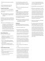
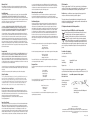
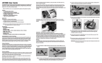
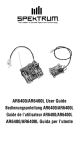
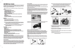
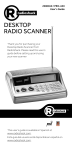
Spektrum AR6250 User Guide
Spektrum’s AR6250 6-channel full range receiver is designed for installations
in compact airplanes constructed of carbon fiber. Carbon fiber can create an RF
shielding effect that can significantly reduce radio range when using conventional
receivers and antennas. The AR6250 features an antenna design that overcomes RF
issues in these critical environments.
Compatibility
The AR6250 receiver features DSM2™ technology and is compatible with all
Spektrum™ and JR® aircraft radios that support DSM2 technology including:
JR12X
JRX9303
Spektrum DX7
Spektrum DX6i
Spektrum DX5e
Spektrum Module Systems
Note: The AR6250 receiver is not compatible with the Spektrum DX6 parkflyer
transmitter.
Features
• 6-channel receiver optimized for carbon fiber fuselage installations
•C
ompact endpin design is ideal for F5D and hand launch sailplanes with small
cross sections
• Offers superior RF coverage with through-the-fuselage feeder antennas
• Includes one internal receiver with two 4-inch (101mm) feeder antennas
• Red LED indicates number of holds
• P reset failsafe system on throttle aileron and elevator optimized for sailplane and
F5D applications
• QuickConnect™ with Brownout Detection
Applications
Compact airplanes with carbon structure including:
• Carbon/ Composite F5D electrics
• Carbon hand launch and DLH gliders
• Carbon Hot-liners
•C
ompact aircraft with significant conductive materials (carbon, aluminum or
other metals) that could weaken the signal
Specifications
Type: DSM2 Full Range receiver for carbon aircraft
Channels: 6
Modulation: DSM2
Dimensions: 35mm x 18mm x 10mm
Weight: 4 grams
Voltage Range: 3.5 to 9.6
Resolution: 1024
Compatibility: All DSM2 aircraft transmitters
Receiver Installation
Airplanes with significant carbon fiber construction can create an RF shielding effect,
reducing range. The AR6250 is designed to overcome these critical RF issues in
carbon airplanes by outfitting the aircraft with two external antennas at specific points
that will ensure secure RF coverage from all angles of the aircraft.
B- 2.4GHz Friendly Fuselage
The section forward of the wing is constructed of non-conductive materials like
fiberglass, Kevlar, etc. but the wing and possibly the tail section have carbon or
carbon weave construction.
Feeder Antennas
The AR6250 incorporates two feeder antennas, which are designed to be easily
mounted through the fuselage in carbon airplanes. The receiver has two 4-inch feeder
antennas. Each feeder antenna includes a coaxial portion (which can be thought of as
an extension) and an exposed 31mm tip antenna. The last 31mm is the active portion
of the antenna.
31mm
Internal Antennas
70 mm
Red LED Hold Indicator
The AR6250 features a red LED (labeled with H) that indicates the number of holds
that have occurred since the receiver was last powered on. The LED will flash the
number of holds then pause (e.g., flash, flash, flash, pause, flash, flash, flash, pause
indicates three holds occurred since the receiver was last turned on). Note that
holds are reset to zero when the receiver is turned off. During the first flights of a
new airplane, it’s recommended to check the red LED hold indicator. If it’s flashing,
it’s important to optimize the installation (move or reposition antennas) until no
hold occurs. On later flights, the LED Hold Indicator can be used to confirm RF link
performance.
Step 1. Identifying the Type of Carbon Aircraft
While some Hand Launch Gliders and F5D airplanes are full carbon construction,
many only use carbon in areas that require extra strength. Some of the latest
aircraft are constructed with 2.4GHz friendly fuselages, meaning that the forward
section of the fuselage is constructed from non-conductive materials like fiberglass
and Kevlar that don’t affect RF. The first step in a proper installation is identifying the
type of fuselage.
2.4GHz Friendly
Step 2. Determining Antenna Mounting Positions
After determining which type of aircraft from the list above, use the above
illustrations as a guideline as to where the feeder antennas should be mounted. Note
that full carbon aircraft requires externally mounted antennas while the 2.4GHzfriendly fuselage can have the antennas mounted internally. The goal is to mount the
antennas in a location so that at least one will always be in the RF visual line of sight
of the transmitter (e.g. not blocked by carbon fiber structures) in all attitudes. This
can easily be visualized by having a helper stand about 20 feet away and rotate the
airplane in all attitudes confirming that in all positions there is a direct line between
you and at least one receiver antenna that isn’t blocked by carbon fiber structure.
A- Full Carbon
All components of the airplane including the entire fuselage, the wing and tail are
constructed of carbon fiber or have a carbon fiber weave throughout the aircraft.
Step 3. Installing the Receivers
Install the receiver in the normal position recommended by the airplane’s
manufacturer. Double-sided tape or foam can be used to secure the main
receiver in place.
External Antennas
Full Carbon
Step 4. Mounting the Antennas
To install the antennas, drill a 1/16-inch hole in the desired antenna mounting
position.
3. M
ove the sticks and switches on the transmitter to the desired failsafe positions
for the throttle, elevator and aileron channels.
Slide the feeder antenna through the hole until the 31mm tip, and about 2mm of
coaxial, completely exit the fuselage. Using a drop of CA, glue the antenna to the
fuselage making sure that the 31mm active portion of the antenna tip is fully exposed.
If any holds occur redo the test, noting the orientation of the aircraft when the holds
occur. This will allow you to change and optimize the antenna position(s) to a better
location.
Note: If the antenna is to be mounted internally (in the front of a 2.4GHz fuse), the
coaxial can be taped into position. Be sure the 31mm tip is located at least 2
inches from any significant carbon structure.
Step 10. Short Test Flight Verification with Hold Indicator
When the system tests successfully, it’s time for a short near test flight. This first flight
should be close (in less than 200 feet) and about five minutes or less. After the flight,
land near yourself and check that no holds occurred. A successful flight will result in
0 holds. Extend the flight distance and times, checking the Hold data after every flight
until you are confident with the results.
Step 5. Plugging in the Servo Leads
Plug the servo leads into the appropriate servo ports in the receiver, noting the
polarity of the servo connector. Consult your radio’s manual for specific details as to
which servo plugs into which servo port channel.
Step 6. Binding the Receiver
The AR6250 must be bound to the transmitter before it will operate. Binding is the
process of teaching the receiver the specific code of the transmitter so it will only
connect to that specific transmitter.
1. To bind an AR6250 to a DSM2 transmitter, insert the bind plug in the BATT/BIND
port on the receiver.
4. F ollow the procedures of your specific transmitter to enter Bind Mode; the
system will connect within a few seconds. Once connected, the orange LED on
the receiver will go solid indicating the system is connected.
5. R emove the bind plug from the BATT/BIND port on the receiver before you
power off the transmitter and store it in a convenient place.
IMPORTANT: Remove the bind plug to prevent the system from entering bind
mode the next time the power is turned on.
2. P ower the receiver through any other port. Note that the orange LED on the
receiver should be flashing, indicating that the receiver is in bind mode and
ready to be bound to the transmitter.
occur. Do this for one minute. The timer on the transmitter can be used here.
5. After one minute, release the range test button. A successful installation will
yield the following: no holds, no flashing red LED.
IMPORTANT: Y-Harnesses and Servo Extensions
When using Y-harness or servo extensions, it’s important to use standard nonamplified Y-harnesses and servo extensions as they can/will cause the servos to
operate erratically or not function at all. Amplified Y-harnesses were developed several
years ago to boost the signal for some older PCM systems and should not be used
with Spektrum equipment. Note that when converting an existing model to Spektrum,
be certain that all amplified Y-harnesses and/or servo extensions are replaced with
conventional non-amplified versions.
Step 7. Radio Setup and Programming
Following the instructions in your radio manual, program your airplane.
Preset Failsafe
The AR6250 features preset failsafe only on throttle, aileron and elevator channels.
Preset failsafe is ideal for sailplanes, allowing the aircraft to automatically
dethermalize if the signal is lost. With preset failsafe, the throttle, aileron and elevator
channels go to their preset failsafe positions if the signal is lost, preventing a flyaway.
Step 8. Rebinding the Receiver
After you’ve programmed your model, it’s important to rebind the system so the true
failsafe control surface positions are set.
Receiver Power Only
• When the receiver only is turned on (no transmitter signal is present), all
channels have no output signal, to avoid overdriving the servos and linkages.
Step 9. Ground Range Testing and Verification Red LED
Advanced Range Testing
In airplanes that have significant carbon fiber construction, it is imperative to first
do an advanced ground range check. This ground range check will confirm that
the receiver is operating optimally and that the antennas are properly mounted in a
position that will give positive RF coverage in all attitudes. This advanced range check
allows the RF performance of the receiver and the positions of each antenna to be
verified and to optimize the locations of the antennas.
Note: S ome analog servos may drift slightly during power-up even though no
signal is present. This is normal.
Advanced Range Test
1. Turn on the system (Tx and Rx).
2. H
ave a helper hold your aircraft while observing the red LED (labeled with H)
located on the receiver.
3. S tanding 30 paces away from the model, face the model with the transmitter in
your normal flying position and put your transmitter into range test mode. This
causes reduced power output from the transmitter.
4. H
ave your helper position the model covering all orientations (nose up, nose
down, nose toward the Tx, nose away from the Tx, etc.) while watching the red
LED, noting any correlation between the aircraft’s orientation and when holds
After Connection
• When the transmitter is turned on and after the receiver connects to the
transmitter, normal control of all channels occurs.
• After the system makes a connection, if loss of signal occurs Preset Failsafe
drives the throttle, aileron and elevator servos to their preset failsafe position set
during binding.
Receiver Power System Requirements
Inadequate power systems that are unable to provide the necessary minimum voltage
to the receiver during flight have become the number one cause of in-flight failures.
Some of the power system components that affect the ability to properly deliver
adequate power include:
• Receiver battery pack (number of cells, capacity, cell type, state of charge)
• The switch harness, battery leads, servo leads, regulators, etc.
• The BEC used in the speed controller won’t support the current required by the
servos.
The AR6250 has a minimum operational voltage of 3.5 volts; it is highly
recommended the power system be tested per the guidelines below.
Recommended Power System Test Guidelines
If a questionable power system is being used (e.g. a small or old battery that may
not support high-current draw, etc.), it is recommended that a voltmeter be used to
perform the following test.
Note: T he Spektrum Flight Log (SPM9540) is the perfect tool to monitor voltage
in the test below. The Flight Log is not compatible with the AR6250 for
recording flight data.
Plug the Flight Log into an open channel port in the receiver and with the system on,
load the control surfaces (apply pressure with your hand) while monitoring the voltage
at the receiver. The voltage should remain above 4.8 volts even when all servos are
heavily loaded.
Note: The latest generations of Nickel-Metal Hydride batteries incorporate a new
chemistry mandated to be more environmentally friendly. These batteries,
when charged with peak detection fast chargers, have tendencies to
false peak (not fully charge) repeatedly. These include all brands of NiMH
batteries. If using NiMH packs, be especially cautious when charging,
making absolutely sure that the battery is fully charged. It is recommended
to use a charger that can display total charge capacity. Note the number of
mAh put into a discharged pack to verify it has been charged to full capacity.
QuickConnect™ With Brownout Detection
Your AR6250 features QuickConnect with Brownout Detection.
• S hould an interruption of power occur (brownout), the system will reconnect
immediately when power is restored (QuickConnect).
• The orange LED on the receiver will flash slowly indicating a power interruption
(brownout) has occurred.
• B rownouts can be caused by an inadequate power supply (weak battery or
regulator), a loose connector, a bad switch, an inadequate BEC when using an
electronic speed controller, etc.
• B rownouts occur when the receiver voltage drops below 3.5 volts thus
interrupting control as the servos and receiver require a minimum of 3.5 volts to
operate.
How QuickConnect With Brownout Detection Works
• When the receiver voltage drops below 3.5 volts the system drops out (ceases
to operate).
• When power is restored the receiver immediately attempts to reconnect to the
last two frequencies that it was connected to.
• If the two frequencies are present (the transmitter was left on) the system
reconnects typically in about a fraction of a second.
QuickConnect with Brownout Detection is designed to allow you to fly safely
through most short-duration power interruptions; however, the root cause of these
interruptions must be corrected before the next flight to prevent catastrophic safety
issues.
Note: If a brownout occurs in flight, it is vital that the cause of the brownout be
determined and corrected.
ModelMatch™
Some Spektrum and JR transmitters offer a feature called ModelMatch that prevents
the possibility of operating a model using the wrong model memory, potentially
preventing a crash. With ModelMatch, each model memory has its own unique code
(GUID) and during the binding process the code is programmed into the receiver.
Later, when the system is turned on, the receiver will only connect to the transmitter if
the corresponding model memory is programmed onscreen.
Note: If at any time you turn on the system and it fails to connect, check to be sure
the correct model memory is selected in the transmitter. Please note that the
Spektrum Aircraft Modules do not have ModelMatch.
Tips On Using 2.4GHz
While your DSM equipped 2.4GHz system is intuitive to operate, functioning nearly
identically to 72MHz systems, following are a few common questions from customers.
1. Q: Which do I turn on first, the transmitter or the receiver?
A: If the receiver is turned on first—all channels have no output pulses. When
the transmitter is then turned on, the transmitter scans the 2.4GHz band and
acquires two open channels. Then the receiver that was previously bound to the
transmitter scans the band and finds the GUID (Globally Unique Identifier code)
stored during binding. The system then connects and operates normally.
If the transmitter is turned on first—the transmitter scans the 2.4GHz band and
acquires two open channels. When the receiver is then turned on for a short
period (the time it takes to connect) all channels have no output pulses. The
receiver scans the 2.4GHz band looking for the previously stored GUID. When it
locates the specific GUID code, it confirms the uncorrupted repeatable packet
information, the system connects and normal operation takes place. Typically
this takes 2 to 6 seconds.
2. Q: S ometimes the system takes longer to connect and sometimes it doesn’t
connect at all?
A: In order for the system to connect (after the receiver is bound) the receiver must
receive a large number of consecutive uninterrupted perfect packets from the
transmitter. This process is purposely critical of the environment ensuring that
it’s safe to fly when the system does connect. If the transmitter is too close
to the receiver (less than 4 feet) or if the transmitter is located near metal
objects (metal Tx case, the bed of a truck, the top of a metal work bench, etc.),
connection will take longer and in some cases connection will not occur as the
system is receiving reflected 2.4GHz energy from itself and is interpreting this
as unfriendly noise. Moving the system away from metal objects or moving the
transmitter away from the receiver and powering the system again will cause
a connection to occur. This only happens during the initial connection. Once
connected, the system is locked in and should a loss of signal occur (failsafe),
the system connects immediately when the signal is regained.
3. Q: I’ve heard that the DSM system is less tolerant of low voltage. Is this correct?
A: All DSM receivers have an operational voltage range of 3.5 to 9.6 volts. With
most systems this is not a problem as, in fact, most servos cease to operate at
around 3.8 volts. When using multiple high-current draw servos with a single
or inadequate battery/ power source, heavy momentary loads can cause the
voltage to dip below this 3.5-volt threshold thus causing the entire system
(servos and receiver) to brown out. When the voltage drops below the low
voltage threshold (3.5 volts), the DSM receiver must reboot (go through the
startup process of scanning the band and finding the transmitter) and this can
take several seconds. Please read the receiver power requirement section as
this explains how to test for and prevent this occurrence.
4. Q: Sometimes my receiver loses its bind and won’t connect requiring rebinding.
What happens if the bind is lost in flight?
A: The receiver will never lose its bind unless it’s instructed to. It’s important to
understand that during the binding process the receiver not only learns the
GUID (code) of the transmitter, but the transmitter learns and stores the type
of receiver that it’s bound to. If the transmitter is placed into bind mode, the
transmitter looks for the binding protocol signal from a receiver. If no signal is
present, the transmitter no longer has the correct information to connect to a
specific receiver and in essence the transmitter has been “unbound” from the
receiver. We’ve had several DX7 customers that use transmitter stands or trays
that unknowingly depress the bind button and the system is then turned on,
losing the necessary information to allow the connection to take place. We’ve
also had DX7 customers that didn’t fully understand the range test process
and pushed the bind button before turning on the transmitter also causing the
system to “lose its bind.”
Warranty Period
Exclusive Warranty- Horizon Hobby, Inc., (Horizon) warranties that the Products purchased (the
“Product”) will be free from defects in materials and workmanship for a period of 1 year from the
date of purchase by the Purchaser.
you can be reached during business days, your RMA number, a list of the included items, method
of payment for any non-warranty expenses and a brief summary of the problem. Your original sales
receipt must also be included for warranty consideration. Be sure your name, address, and RMA
number are clearly written on the outside of the shipping carton.
Limited Warranty
Warranty Inspection and Repairs
(a) This warranty is limited to the original Purchaser (“Purchaser”) and is not transferable. REPAIR
OR REPLACEMENT AS PROVIDED UNDER THIS WARRANTY IS THE EXCLUSIVE REMEDY OF THE
PURCHASER. This warranty covers only those Products purchased from an authorized Horizon dealer.
Third party transactions are not covered by this warranty. Proof of purchase is required for warranty
claims. Further, Horizon reserves the right to change or modify this warranty without notice and
disclaims all other warranties, express or implied.
(b) Limitations- HORIZON MAKES NO WARRANTY OR REPRESENTATION, EXPRESS OR IMPLIED,
ABOUT NON-INFRINGEMENT, MERCHANTABILITY OR FITNESS FOR A PARTICULAR PURPOSE OF
THE PRODUCT. THE PURCHASER ACKNOWLEDGES THAT THEY ALONE HAVE DETERMINED THAT THE
PRODUCT WILL SUITABLY MEET THE REQUIREMENTS OF THE PURCHASER’S INTENDED USE.
(c) Purchaser Remedy- Horizon’s sole obligation hereunder shall be that Horizon will, at its option,
(i) repair or (ii) replace, any Product determined by Horizon to be defective. In the event of a defect,
these are the Purchaser’s exclusive remedies. Horizon reserves the right to inspect any and all
equipment involved in a warranty claim. Repair or replacement decisions are at the sole discretion
of Horizon. This warranty does not cover cosmetic damage or damage due to acts of God, accident,
misuse, abuse, negligence, commercial use, or modification of or to any part of the Product. This
warranty does not cover damage due to improper installation, operation, maintenance, or attempted
repair by anyone other than Horizon. Return of any goods by Purchaser must be approved in writing
by Horizon before shipment.
Damage Limits
HORIZON SHALL NOT BE LIABLE FOR SPECIAL, INDIRECT OR CONSEQUENTIAL DAMAGES, LOSS OF
PROFITS OR PRODUCTION OR COMMERCIAL LOSS IN ANY WAY CONNECTED WITH THE PRODUCT,
WHETHER SUCH CLAIM IS BASED IN CONTRACT, WARRANTY, NEGLIGENCE, OR STRICT LIABILITY.
Further, in no event shall the liability of Horizon exceed the individual price of the Product on which
liability is asserted. As Horizon has no control over use, setup, final assembly, modification or misuse,
no liability shall be assumed nor accepted for any resulting damage or injury. By the act of use, setup
or assembly, the user accepts all resulting liability.
If you as the Purchaser or user are not prepared to accept the liability associated with the use of this
Product, you are advised to return this Product immediately in new and unused condition to the place
of purchase.
Law: These Terms are governed by Illinois law (without regard to conflict of law principals).
Safety Precautions
This is a sophisticated hobby Product and not a toy. It must be operated with caution and common sense
and requires some basic mechanical ability. Failure to operate this Product in a safe and responsible
manner could result in injury or damage to the Product or other property. This Product is not intended
for use by children without direct adult supervision. The Product manual contains instructions for safety,
operation and maintenance. It is essential to read and follow all the instructions and warnings in the
manual, prior to assembly, setup or use, in order to operate correctly and avoid damage or injury.
Questions, Assistance, and Repairs
Your local hobby store and/or place of purchase cannot provide warranty support or repair. Once
assembly, setup or use of the Product has been started, you must contact Horizon directly. This will
enable Horizon to better answer your questions and service you in the event that you may need any
assistance. For questions or assistance, please direct your email to
[email protected], or call 877.504.0233 toll free to speak to the
Product Support department.
To receive warranty service, you must include your original sales receipt verifying the proof-ofpurchase date. Provided warranty conditions have been met, your Product will be repaired or
replaced free of charge. Repair or replacement decisions are at the sole discretion of Horizon Hobby.
Non-Warranty Repairs
Should your repair not be covered by warranty the repair will be completed and payment will be
required without notification or estimate of the expense unless the expense exceeds 50% of the
retail purchase cost. By submitting the item for repair you are agreeing to payment of the repair
without notification. Repair estimates are available upon request. You must include this request with
your repair. Non-warranty repair estimates will be billed a minimum of ½ hour of labor. In addition
you will be billed for return freight. Please advise us of your preferred method of payment. Horizon
accepts money orders and cashiers checks, as well as Visa, MasterCard, American Express, and
Discover cards. If you choose to pay by credit card, please include your credit card number and
expiration date. Any repair left unpaid or unclaimed after 90 days will be considered abandoned and
will be disposed of accordingly. Please note: non-warranty repair is only available on electronics and
model engines.
Electronics and engines requiring inspection or repair should be shipped to the following address:
Horizon Service Center
4105 Fieldstone Road
Champaign, Illinois 61822
All other Products requiring warranty inspection or repair should be shipped to the following address:
Horizon Product Support
4105 Fieldstone Road
Champaign, Illinois 61822
Please call 877-504-0233 or e-mail us at [email protected] with any questions or
concerns regarding this product or warranty.
European Union:
Electronics and engines requiring inspection or repair should be shipped to one of the following
addresses:
Horizon Hobby UK
Units 1-4 Ployters Rd
Staple Tye, Harlow
Essex CM18 7NS
United Kingdom
Please call +44 (0) 1279 641 097 or email [email protected] with any questions or
concerns regarding this product or warranty.
Horizon Technischer Service
Hamburger Str. 10
25335 Elmshorn
Germany
Please call +49 4121 46199 66 or email [email protected] with any questions or concerns
regarding this product or warranty.
FCC Information
This device complies with part 15 of the FCC rules. Operation is subject to the following two
conditions: (1) This device may not cause harmful interference, and (2) this device must accept
any interference received, including interference that may cause undesired operation.
Caution: Changes or modifications not expressly approved by the party responsible for
compliance could void the user’s authority to operate the equipment.
This product contains a radio transmitter with wireless technology which has been tested
and found to be compliant with the applicable regulations governing a radio transmitter in the
2.400GHz to 2.4835GHz frequency range.
CE Compliance information for the European Union
Instructions for Disposal of WEEE by Users in the European Union
This product must not be disposed of with other waste. Instead, it is the user’s
responsibility to dispose of their waste equipment by handing it over to a
designated collection point for the recycling of waste electrical and electronic
equipment. The separate collection and recycling of your waste equipment at
the time of disposal will help to conserve natural resources and ensure that it is
recycled in a manner that protects human health and the environment. For more
information about where you can drop off your waste equipment for recycling, please contact
your local city office, your household waste disposal service or where you purchased the
product.
Declaration of Conformity
(in accordance with ISO/IEC 17050-1)
No. HH20090109
Product(s):
Item Number(s):
Spektrum AR6250 Receiver
SPMAR6250
Equipment class:
1
The objects of declaration described above are in conformity with the requirements of the
specifications listed below, following the provisions of the European R&TTE directive 1999/5/EC:
EN 301 489-1 v.1.6.1
EN 301 489-17 v.1.2.1
General EMC requirements for Radio equipment
Signed for and on behalf of: Horizon Hobby, Inc.
Champaign, IL USA
Jan 9, 2009 Steven A. Hall
Vice President
International Operations and Risk Management
Horizon Hobby, Inc.
Inspection or Repairs
If this Product needs to be inspected or repaired, please call for a Return Merchandise Authorization
(RMA). Pack the Product securely using a shipping carton. Please note that original boxes may be
included, but are not designed to withstand the rigors of shipping without additional protection. Ship
via a carrier that provides tracking and insurance for lost or damaged parcels, as Horizon is not
responsible for merchandise until it arrives and is accepted at our facility. A Service Repair Request is
available at www.horizonhobby.com on the “Support” tab. If you do not have internet access, please
include a letter with your complete name, street address, email address and phone number where
©2009 Horizon Hobby, Inc.
US Patent Number 7, 391, 320. Other patents pending.
DSM and DSM2 are trademarks or registered trademarks of Horizon Hobby, Inc. The Spektrum trademark is
used with permission of Bachmann Industries, Inc. Spektrum radios and accessories are exclusively available
from Horizon Hobby, Inc.
Printed 1/09 14988