1
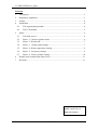
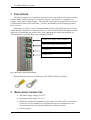
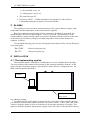
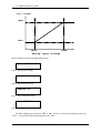
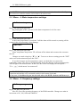
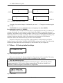
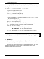
CC HHO-PWM
User's Guide
Software version 1.25
CC HHO-PWM user's guide
Contents:
1
The purpose ................................................................................................................ 3
2
Regulatory capabilities............................................................................................... 3
3
Alarms ........................................................................................................................ 4
4
Installation .................................................................................................................. 4
5
4.1
The implementing module.................................................................................. 4
4.2
The LCD module ................................................................................................ 5
Menu........................................................................................................................... 6
5.1
The main screen.................................................................................................. 6
5.2
Menu – 1.Current regulator mode ...................................................................... 6
5.3
Menu – 2.Work mode ......................................................................................... 7
5.4
Menu – 3. Analog input settings......................................................................... 7
5.5
Menu – 4.Water temperature settings................................................................. 9
5.6
Menu – 5. Frequency settings............................................................................. 9
5.7
Menu – 6. Factory default settings ................................................................... 10
6
Default and recommended alarm levels ................................................................... 11
7
Warranty................................................................................................................... 11
Designer: Jerzy Hetmański
Phone: +48 603 781 110
Email: [email protected]
rev. 14 z 17-05-2013
2 / 13
CC HHO-PWM user's guide
1 THE PURPOSE
The device purpose is to regulate an electrical current especially in a dry and wet cell to
produce HHO. It allows the user to set a direct current ( current source ) regardless of a
voltage ( Wide Input Voltage Range ). The controller is designed to regulate the current in a
cell the distance between the electrodes ≥1.8 mm ( the thickness of the isolating separator
layer is 2mm ).
Installation of cables to screw terminals should be done using cable lugs for screw M5,
which should be adjusted to a diameter of the wire. The terminals should be tighten with the
right tools for mounting lugs on the cable. After tightening the cable to the terminal it's
recommended to secure the bolts with a technical vaseline.
(-) Minus power supply (from accumulator )
(+) Plus power supply (from accumulator )
(+) Plus to cell
(-) Minus to cell
Fig. 1. Description of the main terminals
Recommended connectors for M5 screws (KLAUKE, NINGI or similar):
2
REGULATORY CAPABILITIES
Allowable supply voltage: 8 to 32V
Operating voltage range: 9 to 30 V
Stabilized current (recommended no more than 35A; above 25A it is necessary
for the driver to be installed in a ventilated area eg near a radiator fan or an
external mount fan or to install an additional external heat sink).
Current control:
rev. 14 z 17-05-2013
3 / 13
CC HHO-PWM user's guide
1) the keyboard: every 1A
2) analog input: every 0.1A
The controller type: PI
Frequency: 40 Hz .... 25kHz adjustable in increments of 10 Hz (I do not
recommend setting the frequency of less than 200Hz)
3 ALARMS
The regulator oversees the three main parameters of the system: battery voltage, water
temperature and the temperature of the main transistor regulator.
Based on continuous measurement of these parameters, the alarm is generated. It is
manifested by a short beep repeated approx. every 0.5 seconds. The alarm turns off the
current stabilizer (output current equals zero) and it's maintained till the removal of the cause
of the alarm (eg low battery voltage or too high temperature of the main transistor of a
regulator, or water).
To turn off the beeping, press any key. During the alarm instead of the current, displayed
is the inscription:
„I=!!!A”
– before pressing any key
„I=!!!”
– after pressing any key
4 INSTALLATION
4.1 The implementing module
The controller must be installed in a ventilated area so as to eliminate direct flooding.
The good cooling of the bottom of the housing of the controller should be ensured ( on the
upper side there are plastic stoppers ) because this is where all active components are ( the
main control transistor and diode ).
Socket
Bottom of the housing
Keep cooled!
Fig. 2. Housing. Cooling.
To reduce the loss in the supply system of a cell, power cables of the controller and the
cell should be as thick and as short as possible. The power cables ( a cable "plus" and a cable
"minus") should be guide as close to each other (in an one tube assembly) as possible. This
applies to both the regulator and the power supply of the cell. Cables colors should be chosen
rev. 14 z 17-05-2013
4 / 13
CC HHO-PWM user's guide
according to the standard ie the cable "plus" (positive) should be red, and the cable "minus"
(negative) black.
For a current below 20A recommended are cables in insulation resistant to high
temperatures with a cross section ≥ 4mm2. For current up to 30A ≥ 6mm2, and for 40A ≥
10mm2. The fuse placed in the main power circuit supply for the controller and the cell „Fcel” should be set to match the current of the cell. For Icel ≤ 15A
Fcel = 20A, for Icel ≤ 20A Fcel = 25…30A, for Icel ≤ 30A Fcel = 35…40A.
4.2 The LCD module
Connect the gray, four-wire cable (it's attached to the plug from the outlet of the
implementing module) to the LCD module. This cable should be drag into the cabin at the
shortest route. In the back of the housing of the display there are four screws that need to be
unscrew with a star screwdriver. Then, using a flat screwdriver (about 2mm wide) pull the
back housing panel off.
Before attaching the ends of the cable to the socket, drill a 5mm diameter hole ( in the
back or side wall, in a place convenient for you ) and drag the cable through it.
It's recommended to cut off the excess of the cable leaving only a few inches piece
enabling free connection to the display.
How to connect the cable to the display is shown in the figure below.
brown
yellow
white
green
Fig. 3. How to connect the cable to the display
rev. 14 z 17-05-2013
5 / 13
CC HHO-PWM user's guide
5 MENU
5.1 The main screen
The main screen displays all of the values measured by the controller.
That is:
- stabilized current (I)
- supply voltage (U)
- water temperature (Tw)
- heat sink temperature (Tr)
I=10.0A U=14.1V
Tw=56C Tr=46C
Fig. 4. The main screen
You can switch between the main screen and the menu by pressing the "ESC". The main
menu contains 6 points, which are described below.
5.2 Menu – 1.Current regulator mode
1. I Regul.mode.
Fig. 5. The first point of the menu
By pressing „ENT” we can choose the setting method for the current:
1) „keyboard”
2) „analog input”
Switch by pressing „▼” or „▲”.
I Regul.mode.
keyboard
I Regul.mode.
anal.input
Fig. 6. Menu: Regulator mode
Setting mode "keyboard" allows changing of the current with the keys "▼" or "▲".
Changes in the value of the current setting are possible after the return to the main screen.
This can be done by pressing twice the "ESC" button or waiting about 20 seconds after which
the driver goes to the menu itself, and after another 20 seconds to the main screen.
rev. 14 z 17-05-2013
6 / 13
CC HHO-PWM user's guide
Setting mode "anal.input" allows to change the current settings by connecting the voltage
to the analog input (with an external potentiometer or MAP / MAF signal). Voltage to current
ratio is linear in characteristic, which will be described in section 3.4.
5.3 Menu – 2.Work mode
2.Work mode
Fig. 7. The second point of the menu
By pressing „ENT” we can choose the setting method for the current:
1) „manual”
2) „auto”
Switch by pressing „▼” or „▲”.
Work mode
manual
Work mode
auto
Fig. 8. Menu: Work mode
Setting mode "manual" allows operation independently of the battery voltage.
Set the mode to "auto" causes dependence of the set current of the accumulator voltage.
As a result the controller will automatically turn it on after the voltage exceeds approximately
13.2V (ie after the engine firing) and automatically turn it off after the battery voltage drops
below 12.9V (ie after the engine is turned off). When connected to a 24V the controller
automatically switches these levels to 26.4V and 25.8V. Switch on of current is delayed by 10
seconds after exceeding the level of activation. Switch off current takes place immediately.
5.4 Menu – 3. Analog input settings
3.Anal.inp.set.
Fig. 9. The third point of the menu
By pressing the "ENT" you can set the voltage to cell current supply characteristics.
On the main slot / connector (pin 6) there is the analog input (cable green). You can enter
a voltage of 0 to 30V. It allows control of the stabilized current of the cell in accordance with
the characteristics shown in Figure 7.
rev. 14 z 17-05-2013
7 / 13
CC HHO-PWM user's guide
Cell current
Imax
Imin
Umin
Umax
Analog input voltage
Fig. 10. Voltage to cell current supply characteristics
Umin=0.5V
Fig. 11. The first point voltage.
Imin=10.0A
Fig. 12. The first point current.
Umax=4.2V
Fig. 13. The second point voltage.
Imax=33.3A
Fig. 14. The second point current.
To make changes press the keys "▼" or "▲". To move to the next setting press the key
"ENT". To go back to the main menu press the "ESC".
rev. 14 z 17-05-2013
8 / 13
CC HHO-PWM user's guide
NOTE! In the submenu if no key is pressed for 20 seconds, the driver himself will go to
the main menu, and after another 20 seconds to the main screen.
5.5 Menu – 4.Water temperature settings
4.Water temp.
Fig. 15. The fourth point of the menu
By pressing the „ENT” you can set the alarm temperature levels for water.
TwH=65C
Fig. 16. The fourth point of the menu
If the water temperatures exceeds the TwH the alarm will be turned on, turning off the
current in the cell protecting it from damage.
TwL=60C
Fig. 17. The fourth point of the menu
Water temperature drop below TfL will turn off the alarm and reconnect the current to
the cell.
Changes are made using keys "▼" or "▲". To move to the next setting press the "ENT"
and to exit to the main menu press the "ESC".
If you don't want to use the temperature sensor, you don't have to connect the
temperature sensor. The driver will automatically detect the absence of the measuring probe
and will ignore this measurement. In this case, the screen will display the inscription
"Tw = _np_" which means "not connected".
WARNING! The temperature sensor should be mounted on the cable between the
expansion tank and the cell or mounted outside in the bottom of the tank.
In any case, it should not be put into the tank where the KOH solution could destroy it.
5.6 Menu – 5. Frequency settings
5.Frequency set.
Fig. 18. The fifth point of the menu
Here we can set the operating frequency of the PWM controller. Changes are make in
increments of 10, 100, 1000 and 10000 Hz
rev. 14 z 17-05-2013
9 / 13
!
CC HHO-PWM user's guide
f=24000Hz
^
868
-- ENT f=24000Hz
^
868
-- ENT -- ENT
f=24000Hz
^
868
-- ENT f=24000Hz
^
868
-- ENT -- ENT Fig. 19. Switching and frequency change
Currently, the position change is indicated by an arrow "^". Changes are made using the
"▼" or "▲".
WARNING! It's not recommended to set a frequency less than 2000Hz.
Recommended frequency is 24000Hz.
The number you see on the screen after "Hz" is proportional to the duty cycle that is, the
average cell voltage. It varies from 0 to 1000 (filling of the PWM is in parts per thousand /
promiles). This allows you to find the resonance of the cell. You should find the frequency for
which this number is as small as possible. There, the cell achieves the highest efficiency. The
resonance frequency depends on the cell construction and sometimes it is difficult to
determine. Some cell constructions may not show clear minimums.
Because of the power losses especially in the regulator it is important to provide the
highest frequency (preferably 24000Hz) and PWM digit as large as possible. Top like during
normal operation (after the warm-electrolyte) is not less than 700 (see Chapter 6).
5.7 Menu – 6. Factory default settings
6.Default set.
Fig. 20. The sixth point of the menu
Here, you can restore the factory settings for all parameters of the controller. The string
of characters located in the second line is the serial number of the controller.
NOTE! IMPORTANT!
After the factory reset the measurement error may be up to ± 20% for the current
measurement and ± 10% for the voltage measurement. The driver should be recalibrated. Without adequate instruments it's impossible.
[ENT]-def.set.
[ESC]-<cancel>
Fig. 21. The screen
rev. 14 z 17-05-2013
10 / 13
CC HHO-PWM user's guide
Pressing the "ENT"key will set the factory settings. Pressing the "ESC" key or not
pressing any key for 20 seconds will exit from the sixth point of the menu without changing
the settings.
6 DEFAULT AND RECOMMENDED ALARM LEVELS
Recommended settings of the alarm levels:
1) Temperature of the cell (electrolyte):
TwH = 65 ºC – turn off the current of the cell
TwL = 60 ºC – turn on the current of the cell
2) Factory settings that can be changed only when the service code is given or by using
the service program for the PC:
UbL = 12.9 – turn off voltage level [V]
UbH = 13.2 – turn on voltage level [V]
kP = 200 – proportional factor of the PI controller (changes not recommended)
kI = 75 – integrating factor of the PI controller (changes not recommended)
delON = 10 – time delay (in seconds)
Imax = 40.0 – maximum current (= 40.0 A) for digital security
(Do not increase!). This value can be reduced at most.
TrH = 85 ºC – the temperature of the heat sink, which turns off the current of the cell
TrL = 75 ºC – the temperature of the heat sink, which turns on the current of the cell
ATTENTION !!!
With these parameters, it is NOT RECOMMANDED to change the setting Kp, Ki,
and Imax. This can lead to unstable operation or damage to the controller.
7 WARRANTY
If the user will use the device as intended, device will be installed in accordance with
manufacturer's instructions and in the right location specified in the manual the manufacturer
warranties for a period of 12 months.
The warranty does not cover any mechanical or electrical damages resulting from wrong
installation or misuse. It does not cover a damage resulting from short circuits during
installation or within the hydrogen generator.
rev. 14 z 17-05-2013
11 / 13
!
LCD display
pin nr
1
1
brown
2
yellow
3
white
4
green
description
LCD +5V (brown)
2
SCL
3
SDA
4
LCD - GND (green)
(option)
Additional connection to GND in-car
green
Signal (from MAP / MAF or any different signal)
GND
LCD display + keyboard
NOTE!!
It is only connection
example. You will need
finding real connection on
your sensor MAP/MAF.
Analog output; signal MAP/MAF
MASA POJAZDU
Fuses
F1
1...5A
F2
Controller
Temperature sensor.
Do not put into the electrolyte!!!!
Attach this sensor to the delivery
pipe to the cell electrolyte.
F3
Controller HHO
purple
black
yellow
green
purple
black
HHO CELL 12V or 24V
30A...45A
-
12V or 24V
SCL (yellow)
4
SDA (white)
5
+ temp. sensor H2O
6
analog input
7
GND
8
+5V/50mA
9
LCD - GND (green)
10
LCD +5V (brown)
11
- temp. sensor H2O
12
+12V (ACC sig. after ignition
9 3
ACC (+ 12V or 24V after ignition)
+
RS-TTL RxD
3
8 2
brown
white
for current to 40A - 10mm2 (7 AWG)
for current to 30A - 6mm2 (9 AWG)
for current to 20A - 4mm2 (11 AWG)
description
RS-TTL TxD
2
7 1
Fn
Temperature sensor
pin nr
1
10 4
11 5
12 6
4
LCD display + keyboard
7
8
LCD display
A
2
SCL
3
SDA
4
LCD - GND (green)
1
2
4
description
LCD +5V (brown)
brown
B- B+ D+
6
pin nr
1
yellow
Alternator
A
5
3
3
white
2
green
1
(option)
GND
green
IMPORTANT!! Additional connection to GND in-car
Signal (from MAP / MAF or any different signal)
NOTE!!
It is only connection
example. You will need
finding real connection on
your sensor MAP/MAF.
Analog output; signal MAP/MAF
Fn
B
B
Lamp of charginig
MASA POJAZDU
Controller
Additional switch
pin nr
1
Controller HHO
F1
2
RS-TTL RxD
7 1
3
SCL (yellow)
8 2
4
SDA (white)
9 3
5
+ temp. sensor H2O
10 4
6
analog input
11 5
7
GND
12 6
8
+5V/50mA
9
LCD - GND (green)
10
LCD +5V (brown)
11
- temp. sensor H2O
12
+12V (ACC sig. after ignition
1...5A
Temperature sensor.
Do not put into the electrolyte!!!!
Attach this sensor to the delivery
pipe to the cell electrolyte.
Temperature sensor
purple
purple
black
C
yellow
green
black
brown
white
ACC (+ 12V or 24V after ignition)
description
RS-TTL TxD
C
HHO CELL 12V or 24V
30A...45A
for current to 40A - 10mm2 (7 AWG)
for current to 30A - 6mm2 (9 AWG)
for current to 20A - 4mm2 (11 AWG)
D
+
-
D
12V or 24V
Schemat of second variant of connection
1
2
3
4
5
6
7
8