1
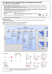
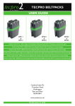
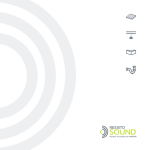
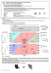
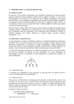
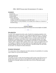
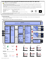
1633 USER GUIDE DIN RAIL MOUNTED RTD/RESISTANCE/SLIDE WIRE TRIP AMPLIFIER
IMPORTANT - CE & SAFETY REQUIREMENTS
Important - Potentially Hazardous situations. Persons responsible for the installation and operation of this equipment must be fully aware of all aspects of this guide. Failure to follow
the instructions can cause severe injuries and damage.
This product is suitable for environment Installation category II pollution degree. The product is classed as "PERMANENTLY CONNECTED EQUIPMENT", and must be DIN rail mounted,
inside a suitable enclosure providing environmental protection to IP65 or greater.
Dc supply must be derived from a local supply and not a distribution system. Max relay contact rating 250 V AC @ 1 a (30 V DC @ 1A). Any circuit connected to a contact must be fused
with a 2 A (T) fuse.
To maintain CE EMC requirements , input and supply wires must be less than 30 metres. The product contains no serviceable parts , or internal adjustments. No attempt must be made
to repair this product. Faulty units must be returned to supplier for repair. This product must be installed by a qualified person. All electrical wiring must be carried out in accordance
with the appropriate regulations for the place of installation. Before attempting any electrical connection work, please ensure all supplies are switched off.
ABSOLUTE MAXIMUM CONDITIONS ( To exceed may cause damage to the unit):Supply Voltage
± 50 V dc (Protected for over voltage and reverse connection)
Current with over voltage
± 200 mA
Input Voltage
± 5 V between any terminals
Input Current
± 10 mA between terminals
Ambient
Temperature (-30 to 75) °C Humidity (10 to 95) % RH (Non condensing)
PLEASE REFER TO THE PRODUCT LABEL FOR MANUFACTURERS CONTACT DETAILS.
Every effort has been taken to ensure the accuracy of this document, however we do not accept responsibility for damage, injury, loss or expense resulting from errors and omissions, and
we reserve the right of amendment without notice.
RECEIVE AND UNPACKING
Please inspect the packaging and instrument thoroughly for any signs of transit damage. If the instrument has been damaged, please
notify your supplier immediately.
OPERATION (please refer to data sheet for full technical specification.)
CONTROLLER
Additional Data :- Tag number, Process Units, Process Data
I/P SIGNAL
User settings
FILTER
TEMPERATURE
UNITS
9
8
TRIP
A
TRIPS A (B)
Select filter
RTD
Select from 9
sensor types
(Additional
sensor can be
downloaded
from library)
USB
User settings
TEMPERATURE
2
Select °C or °F
Time
constant
(0 to 100) S
Trip Action
3
Low/High/
Proportional
Inverted Low/High/
Proportional
7
SIGNAL
SIGNAL
Select either
Resistance
(0 to 10000)
1
LINEARISATION
User Setting
Select
(2 to22)
Signal to process
segment
TRIP
B
4
Set point
5
Dead band
6
(Proportional)
Process
High Band
POWER SUPPLY
Input (10 to 48)Vdc
or (10 to 32)Vac
Low Band
Slide Wire
(0 to 100)%
Signal
11
12
RANGE LED
HIGH
OK
(GREEN)
DEVIATION
LOW
SENSOR ERROR
(RED)
HB
SP
ALARM LEDS
DB
DB
SP
LB
ON
(RED)
OFF
Trip on outside band
POWER OFF
When power is off relays go into alarm state.
KEY
SP = Set point
DB = Dead Band
HB = High Band
LB = Low Band
D2523-01-01 SEM1633 User Guide
HB
SP
TRIP ACTIONS
DB
DB
SP
LB
TRIP ON
TRIP OFF
Trip on inside band
INVERTED HIGH
INVERTED LOW
DEVIATION
MECHANICAL INSTALLATION
TOP
MOUNTING
1
2
3
4
5
6
70°C
Screw driver
Ø 3 mm
-30°C
TRIP A
>= IP65
90 mm
TRIP B
RANGE
USB
EN50022 DIN RAIL
7
8
9
10 11 12
56.4 mm
17.5 mm
Style
Material
Terminals
Cable
Colour
To fit or release module
Insert screw driver into slot and lever latch away from body
DIN 43880 (1 module width)
Polyamide 6.6 self extinguishing
Screw terminal
2.5 mm Max
Grey
CONFIGURATION
This product is configured using the USB port of a PC running USB_Speed_Link software, available from
your suppliers web site. During configuration the product is powered direct from the usb port, removing
the need for additional power. If the user wishes to monitor live process data during configuration, then
powered must be applied. Note the input and USB port of the device share the same ground, therefore
care must be taken to ensure isolation between PC and input circuit. This is best achieved by using a
portable laptop or notebook PC. USB_Speed_Link software is provided with detailed help menu to guide
the user through the simple configuration procedure. Unless specified at the time of order this product is
supplied with the default configuration listed below.
Factory default:
Input type
= PT100
Units
= °C
Trip A
= High
Setpoint Trip A
= 50
Hysterisis Trip A
= 0.1
Trip B
= High
Setpoint Trip B
= 50
Hysterisis Trip B
= 0.1
Filter
=0
ELECTRICAL INSTALLATION
INPUT CONNECTION
For cable length < 3 Metres no screen or twist pair required.
RTD inputs all three wire must be equal length (resistance).
Use recommended types for cable length (3 to 30) metres.
1.0 TURN OFF SUPPLY BEFORE WORKING ON ANY ELECTRICAL CONNECTION.
2.0 MAX CONTACT RATING 250 V ac (30 V dc) @ 1 A. IMPORTANT! FUSE CONTACT CIRCUITS 2 A (T).
3.0 SUPPLY IS OVER VOLTAGE PROTECTED AND FUSED WITH INTERNAL RESSETTBLE FUSE.
SUPPLY
TRIP A
INPUT
Screened Cable
Resistance/
RTD
11
9
+
N/C
1
Vdc
Screw Driver
2
N/O
8
Ø 3 mm
7
3
Common
Fuse 2.0 A (T)
TRIP B
Slide Wire
8
4
N/C
5
N/O
7
6
9
D2523-01-01 SEM1633 User Guide
Common
Fuse 2.0 A (T)
12
_
Vdc