1
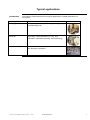
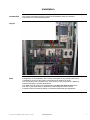
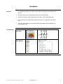
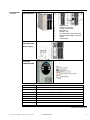
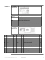
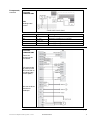
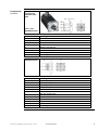
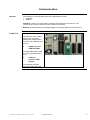
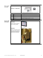
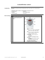
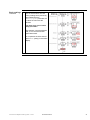
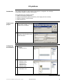
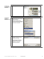
Twido and Lexium
Magelis and Advantys
System User Guide
33003565.02
[source code]
Contents
Application Source Code ..............................................................................................................3
Typical applications ......................................................................................................................4
System....................................................................................................................................5
Architecture.............................................................................................................................5
Installation...............................................................................................................................7
Hardware .............................................................................................................................................................8
Software ............................................................................................................................................................14
Communication .................................................................................................................................................15
Implementation .....................................................................................................................21
Lexium05 drive control ......................................................................................................................................23
I/O platform........................................................................................................................................................25
PLC....................................................................................................................................................................28
HMI ....................................................................................................................................................................41
Appendix.....................................................................................................................................53
Detailed Component List.......................................................................................................53
Component Features ............................................................................................................54
Contact .......................................................................................................................................58
Introduction
This document is intended to provide a quick introduction to the described System.
It is not intended to replace any specific product documentation. On the contrary, it offers
additional information to the product documentation, for installing, configuring and starting up the
system.
A detailed functional description or the specification for a specific user application is not part of
this document. Nevertheless, the document outlines some typical applications where the system
might be implemented.
Twido and Lexium Magelis and Advantys_EN.doc – June-05
Schneider Electric
2
Abbreviations
Word/Expression
PLC
HMI
PC
AC
DC
PSU
I/O
VSD (VVD)
CB
Twido
TwidoSoft
Phaseo
Magelis
Lexium/Lexium05
Advantys
Explanation
Programmable Logic Controller
Human Machine Interface
Personal Computer
Alternating Current
Direct Current
Power Supply Unit
Input/Output
Variable Speed Drive (Variable Velocity Drive)
Circuit Breaker or motor protection
Name of a small Schneider Electric PLC
Name of Schneider Electric PLC programming software
Name of a Schneider Electric range of power supply units
Name of a Schneider Electric range of HMIs
Name of a Schneider Electric range of servo drives
Name of Schneider Electric I/O modules
Application Source Code
Introduction
Examples of the source code used to attain the system function as described in this document
can be downloaded from our „Village“ website under this link.
Twido and Lexium Magelis and Advantys_EN.doc – June-05
Schneider Electric
3
Typical applications
Introduction
The following chapter describes some typical applications or partial applications for
this system.
Application
Description
Packaging machines
In the packaging industry, for labeling, packaging, filling
and palletizing goods
Special-purpose
machines
Used on small special-purpose machines for assembly,
processing, cutting operations, etc. (e.g. food
preparation, automated assembly, wood machining).
Material conveyors
Used in connection with transportation tasks that involve
“pick and place” operations.
Twido and Lexium Magelis and Advantys_EN.doc – June-05
Schneider Electric
Example
4
System
Introduction
This section describes the architecture, components, size and number of the
components that are used within this system.
Architecture
Overview
The system consists of a PLC that controls two drive controls, each with a servo
drive, and a remote I/O platform. The drives can be operated via a graphic touch
panel. The field bus level operates with CANopen and the control level operates with
Modbus. A master switch ensures safety.
Layout
Twido and Lexium Magelis and Advantys_EN.doc – June-05
Schneider Electric
5
Components
Hardware:
• Twido (PLC)
•
Phaseo (power supply)
•
Lexium05 (drive control)
•
Advantys STB (remote I/O)
•
Magelis XBTG (HMI)
•
Servo motor
Software:
• TwidoSoft 3.2 (PLC)
Dimensions
•
Advantys configuration software 1.20 (remote I/O)
•
Vijeo-Designer 4.2.0 (HMI)
•
PowerSuite 2.0 (Lexium05)
The compact size of the individual components means that it is possible to house
them in a control cabinet with the following approximate external dimensions: 700 x
500 x 250 mm (WxHxD). The XBTG can be installed in the front door for operation
there.
Twido and Lexium Magelis and Advantys_EN.doc – June-05
Schneider Electric
6
Installation
Introduction
This section describes the steps required for the hardware setup and software
configuration for the following application.
Layout
Note
Configuration of this application has not been developed for any special actual use. It
is intended to show how the system components work together as a unit.
The components that are listed are a cross-section of the components needed for
control and display in possible applications.
This SMD does not claim to be comprehensive and does not absolve users from
their duty to check the safety requirements of their equipment and to ensure
compliance with the relevant national or international standards and regulations.
Twido and Lexium Magelis and Advantys_EN.doc – June-05
Schneider Electric
7
Hardware
General
Components
•
For assembly purposes, the Twido, power supply and Advantys STB require a tophat rail.
•
The other devices can be attached directly to the mounting plate.
•
A 230 V AC wiring is used between the main switch, power supply and VSD.
•
A 24 V DC wiring is used between the power supply, PLC, HMI and VSD control
unit.
•
There are other cables from the power cables and feedback cables between the
motor and the VSD.
Master switch
VCF-02GE
Power supply
ABL7RE2403
Continued on next page
Twido and Lexium Magelis and Advantys_EN.doc – June-05
Schneider Electric
8
Components,
Twido PLC
continued
TWDLMDA40DTK
1
2
3
4
5
6
7
8
9
Hinged cover
Extension connector
Analog potentiometer
Serial port 1
Module cover
24 V DC power supply terminals
Analog voltage supply connector
LEDs
I/O terminals
Twido PLC
TWDLMDA40DTK
Power supply
•
Drive control
Lexium05
LXM05AD10M2
AC and motor connection
Connections
Meaning
PE
Ground connection
L1, L2/N
AC connection for single-phase equipment
L1, L2, L3
AC connection for three-phase equipment
DC+
DC bus
RBI
Internal ballast
RBE
External ballast
DC-
DC bus
U, V, W
Motor connections
Continued on next page
Twido and Lexium Magelis and Advantys_EN.doc – June-05
Schneider Electric
9
Components,
continued
Drive control
Lexium05
LXM05AD10M2
Overview of signal connections
Connections/
Switches
CN1
Meaning
Analog inputs +/-10 V, pins 11 to 14
CANopen, pins 21 to 23
Digital inputs/outputs, pins 31 to 39
CN2
Motor encoder (Hiperface sensor)
CN3
24V power supply
CN4
PC, remote operating terminal, MODBUS, CANopen; (RJ45)
CN5
ESIM A/B/I out, PULS/DIR in, encoder A/B/I in
S1
Switch for CANopen terminating resistor
Drive control
Lexium05
LXM05AD10M2
Motor encoder
Pin
Signal
Motor,
Pin
1
12
Shield filler wires
SIN
8
6
REFSIN
11
COS
5
Color 1)
Pair
Meaning
I/O
Shield filler wires
white
1
Sine signal
E
4
brown
1
Reference for sine signal, 2.5 V
A
9
Green
2
Cosine signal
E
REFCOS
5
yellow
2
Reference for cosine signal, 2.5 V
A
8
Data
6
gray
3
Receive data, send data
I/O
2
Data
7
pink
3
Receive data, send data, inverted
10
ENC_0V
11
blue
4
I/O
2
Reference voltage encoder (0.5 mm )
A
2
red
4
Not assigned (0.5 mm )
black
5
Reference potential for T_MOT
violet
5
Not assigned
3
TMOT_0V
9
T_MOT
2
gray/pink
6
PTC temperature sensor
E
4
ENC+10V_OUT
10
red/blue
6
10 V DC supply for encoder, max. 150 mA
A
7
1)
1
n.c.
-
Not assigned
Colors quoted refer to the supplied cable.
Continued on next page
Twido and Lexium Magelis and Advantys_EN.doc – June-05
Schneider Electric
10
Components,
continued
Drive control
Lexium05
LXM05AD10M2
24V power supply
HBC
Holding brake
control
Pin
41
42
43
44
Signal
0 VDC
0 VDC
+24 VDC
+24 VDC
Meaning
Reference voltage for 24 V supply
Reference voltage for 24 V supply
24V supply voltage
24V supply voltage
Drive control
Lexium05
LXM05AD10M2
Wiring for field bus control, NO secure hold
Terminals
33-39 must be
connected.
The motor brake
(if present) must
be connected via
a holding brake
control (HBC)
We use the RJ45
terminal for
CANopen.
Continued on next page
Twido and Lexium Magelis and Advantys_EN.doc – June-05
Schneider Electric
11
Components,
continued
AC synchro
servomotors
SER3683L5SSO
AOO
Power cable
GEA2M0AAAA003
Pin
1
2
3
4
A
B
C
D
Meaning
U
PE
W
V
Brake (not assigned)
Brake (not assigned)
Not assigned
Not assigned
Feedback cable
GEA2EAAAAA003
Pin
1
2
3
4
5
6
7
8
9
10
11
12
Meaning
PTC/NTC temperature sensor
PTC/NTC temperature sensor
Not assigned
REF SIN
REF COS
RS 485 positive data
RS 485 negative data
+ SIN
+ COS
Us 7-12 V
GND
Not assigned
Continued on next page
Twido and Lexium Magelis and Advantys_EN.doc – June-05
Schneider Electric
12
Components,
continued
HMI
Magelis
XBT-G2330
Advantys STB
Advantys STB
Power supply
1
2
3
4
Twido and Lexium Magelis and Advantys_EN.doc – June-05
+24 VDC sensor bus power
–24 VDC return line of sensor power supply
+24 VDC actuator bus power
–24 VDC return line of actuator power supply
Schneider Electric
13
Software
General
The software for the Twido PLC, the Magelis graphic touch panel and the Advantys
configuration needs to be installed.
There is an input panel (HMI) with display and keys on the front of the drive control
for ease of parameterization. You will need to install the PowerSuite software in
order to maximize user-friendliness for parameterization, saving and simulation of
the drive control.
The PC needs to have a Microsoft Windows® operating system installed, either
Windows® 2000 or Windows® XP.
Twido and Lexium Magelis and Advantys_EN.doc – June-05
Schneider Electric
14
Communication
General
The methods of communication below are used between devices:
• CANopen
• Modbus
CANopen is used for communication at field bus level between the Twido PLC, the
Lexium 05 drive controls and the remote Advantys I/O platform.
Modbus is inserted between the Magelis graphic touch panel (HMI) and the Twido PLC.
Twido PLC
1
TWD LMDA 40DTK
The TSX PCX 1031 cable is
used for the connection
between the serial interface
of the PC with TwidoSoft and
the PLC.
2
RS485 extension
TWD NOZ 485D
The XBT Z968 cable is used
to connect the HMI and the
PLC.
3
CANopen
extension TWD
NC01M
The standard CANopen
plugs and cables are used.
Twido and Lexium Magelis and Advantys_EN.doc – June-05
Schneider Electric
15
Drive control
Lexium05
LXM05AD10M2
CANopen via CN4 (RJ45)
Pin
1
2
7
8
Magelis XBTG2330 HMI
Signal
CAN_H
CAN_L
MOD+10V_OUT
MOD_0V
Meaning
Data line
Data line, inverted
10 V supply (different assignment from CANopen)
Reference potential for MOD+10V_OUT
XBTZ968
XBTZG999
Communication cables for
PLC including adapter.
XBTZG915
Power supply
Serial communication cable
to PC (with Vijeo Designer).
The Ethernet interface can
be used as an alternative.
Twido and Lexium Magelis and Advantys_EN.doc – June-05
Schneider Electric
16
Advantys STB
CANopen connector
Use the following switches to
set the baud rate (500
kbaud) and address (8).
Pin
1
2
3
4
5
6
7
8
9
Signal
Not used
CAN_L
CAN_GND
Not used
CAN_SHLD
GND
CAN_H
Not used
Not used
Meaning
Reserved
CAN bus line, Low
CAN ground
Reserved
Optional CAN shield
Optional ground
CAN bus line, High
Reserved
Reserved
Note: The pin numbers are shown in the figure above.
Continued on next page
Twido and Lexium Magelis and Advantys_EN.doc – June-05
Schneider Electric
17
Advantys STB,
continued
Programming cable
STB XCA 4002
For connection to the serial
interface of a PC with
Advantys software.
Twido and Lexium Magelis and Advantys_EN.doc – June-05
Schneider Electric
18
CANopen
1
CANopen Adapter
VW3 CAN TAP2
2
CANopen ATV31
VW3 CAN CA RRz
branching cable
available in various
lengths
3
PLC with
CANopen Master
TWD NCO1M
4
Main cable
5
VW3 A8106
PowerSuite cable
Connection between
PC with PowerSuite
software and a
Lexium05.
Pin
1
2
3
4
5
Signal
GND
CAN_L
SHLD
CAN_H
(V+)
Meaning
Optional ground
CAN bus line, Low
Optional shielding
CAN bus line, High
Optional supply (1)
Continued on next page
Twido and Lexium Magelis and Advantys_EN.doc – June-05
Schneider Electric
19
CANopen,
continued
Plug 103643
(including terminating resistor
for connection to
TSXCPP110 Tap and
Advantys)
Cable
DCA 701
(44170014 by Selectron) or
UNITRONIC BUS CAN
2170261 (by LAPP)
Pin
2
3
7
Signal
CAN_L
CAN_GND
CAN_H
Twido and Lexium Magelis and Advantys_EN.doc – June-05
Meaning
CAN bus line, Low
CAN ground
CAN bus line, High
Schneider Electric
20
Implementation
Introduction
This chapter describes how to initialize, parameterize, program, and start up the
system.
Function
Functional description
1. After the power is switched on, all devices run through the initialization stage and
the PLC starts communication. Pressing the “Power up” button on the Magelis
touch panel for two seconds then puts the Lexium05 drive controls into “run”
status. It changes automatically to “speed mode” at this point.
2. After power up, the controller is in manual mode. This gives the user access to
the status machine of the two drive controls, which can both be started and
stopped manually. Their speed and direction can also be set.
3. The drive controls must be stopped to change to automatic mode.
The “Auto” button selects automatic mode and starts speed regulation. The
speed increases from 0 to 600 rpm within one minute. This is maintained for 10
seconds and then changes to -600 rpm in two minutes. After another 10 seconds
at the same speed, the motor is brought down to 0 rpm within one minute. After
a waiting time of 10 seconds the ramp starts again.
4. If an error occurs, the error number is displayed on the touch panel. The user
can look up the description of the error in the operating manual.
Layout
Twido and Lexium Magelis and Advantys_EN.doc – June-05
Schneider Electric
21
Order of tasks
Proceed as follows to optimize the setup time of the individual products:
1. Set the initial parameters of the drive control via the integral operating panel
2. Set up the I/O platform using Advantys Config tool
3. Set up the user program by means of TwidoSoft
4. Set up display (HMI) using Vijeo Designer
Proceeding in the sequence described above will ensure that the relevant
information can either be imported directly or entered manually from the previous
action.
Twido and Lexium Magelis and Advantys_EN.doc – June-05
Schneider Electric
22
Lexium05 drive control
Introduction
This section describes the basic settings that have to be made on the Lexium05 drive
controls.
In particular, these include the communication parameters such as:
• Field bus type
CANopen
• Address
5 or 6 in this instance
• Transfer speed
500 kbaud
Basic settings
1
2
After wiring is complete the drive control parameters must be set.
Parameters can be edited via
the integral operating panel
(HMI).
1
2
3
4
5
6
7
LEDs for CANopen
ESC
- Exit from a menu or a parameter
- Return to the last saved value
ENT
- Call up a menu or a parameter
- Save the displayed value
Down arrow
- Change to the next menu or
parameter
- Decrease the displayed value
Up arrow
- Change to the previous menu or
parameter
- Increase the displayed value
Red LED lit (DC bus live)
7-segment 4-character display
Continued on next page
Twido and Lexium Magelis and Advantys_EN.doc – June-05
Schneider Electric
23
Basic settings
continued
3
When the drive is supplied with
24V for the first time, or if the
factory settings have previously
been loaded with the
PARfactorySet parameter, all
the drive functions are still
blocked.
You must carry out an initial
setup procedure.
This example uses the address
(Adr.) 5 or 6 and the transfer
speed 500 kbaud.
On completion the drive should
report “RDY” (ready) in the status
display.
Twido and Lexium Magelis and Advantys_EN.doc – June-05
Schneider Electric
24
I/O platform
Introduction
This section describes how the Advantys I/O platform is configured. The Advantys
configuration software is used for this purpose.
We suggest that you proceed as follows:
• Create a new project (workspace)
• Configure the hardware (network interface, power supply and I/O modules)
• Configure CANopen communication
• Create the EDS file
Create a new
project
Configuring
the hardware
1
After starting the Advantys
configuration software, you must
create a new workspace.
2
To do this, specify the path, the
workspace name and the name
of the first island.
1
Select the network interface for
CANopen:
• STB NCO 2212
2
Next, add the other stations:
• STB PDT 3100
• STB DRC 3210
• STB DDI3610
• STB ACO 1210
• STB ACI 1230
Remember the bus connection!
• STB XMP 1100
3
Continued on next page
Twido and Lexium Magelis and Advantys_EN.doc – June-05
Schneider Electric
25
Configuring
the hardware,
4
The display should look like this.
1
The internal baud rate can be
set via the menu bar. The rate
used is 500 kbps.
Set the parameter for the
transfer rate between NIM and
PLC with the two rotary switches
on the front of the NIM.
2
Finally, the EDS file needs to be
created by selecting “Export”
from the “File” menu.
continued
Configuring
CANopen
communication
The name and location are
freely selectable. This file is
required for subsequent
processing operations.
Twido and Lexium Magelis and Advantys_EN.doc – June-05
Schneider Electric
26
Assign I/Os
1
You can use the “I/O Image
Overview…” menu item or the
icon to call the function for
assigning I/Os to memory areas.
The information concerning the
selected data is displayed in the
description field.
Alternatively, the project can
also be printed out. The printout
will contain the same
information.
Twido and Lexium Magelis and Advantys_EN.doc – June-05
Schneider Electric
27
PLC
Introduction
The PLC section describes the various steps for setting up the PLC logic. TwidoSoft is
used.
Proceed as follows to integrate the PLC:
• Create a new project
• Configure the hardware (central unit + modules)
• Configure Modbus communication
• Configure CANopen communication
• Set up the user program
• Connect the PLC to the PC
• Transfer the user program to the PLC
Create a new
project
1
After starting the software, the
first thing you need to do is
create a new project.
2
Select the functional level and
then enter an application name.
Twido and Lexium Magelis and Advantys_EN.doc – June-05
Schneider Electric
28
Configure the
hardware
1
If the power base that is offered
is not the one used you must
change it.
Select the PLC power base
Configure
Modbus
communication
2
Then add the additional RS485
interface.
1
The appropriate interface
parameters need to be entered.
Communication type: Modbus
Address: 1 for PC (Port 1)
2 for HMI (Port 2)
Baud rate:
19200 baud
The settings for Port 2 must be
the same as those for the HMI.
Twido and Lexium Magelis and Advantys_EN.doc – June-05
Schneider Electric
29
Configure
CANopen
communication
1
Add the modules for the
extension.
2
First the CANopen master and,
in our example, analog input
and output modules (one of
each).
3
The following should then be
displayed in the application
navigator.
4
The project can be saved at any
time with “Save As…” and later
with “Save”.
5
The configuration tool must be
opened to configure the
CANopen Master.
Continued on next page
Twido and Lexium Magelis and Advantys_EN.doc – June-05
Schneider Electric
30
Configure
6
CANopen
communication,
continued
First the EDS files must be
imported.
Click on the “import/update”
button in the window.
7
Next select, firstly the EDS file
created by the Advantys
software.
Then select the EDS file that
belongs to the drive control.
8
Use the “Add” button to move
both of the drive controls and
the Advantys into the program
block. Then position them at the
correct address using the
“higher/lower” buttons.
After this, select a baud rate of
500 kbit/s and change the name
of the slave as desired.
This is the result.
Continued on next page
Twido and Lexium Magelis and Advantys_EN.doc – June-05
Schneider Electric
31
Configure
9
CANopen
communication,
continued
The “Mapping” tab holds
information on the contents of
the individual PDOs. No
changes are needed here.
To send and receive, the two
Advantys PDOs and the PDO 3
for each Lexium must be added
to the “Linking” tab.
This produces the following
image.
The same applies to
communication in the other
direction.
10 The “Symbol” tab contains the
address assignment.
The configuration editor window
also shows this information.
Continued on next page
Twido and Lexium Magelis and Advantys_EN.doc – June-05
Schneider Electric
32
Configure
11 Autostart is one of the features
that can be activated using the
CANopen
menu bar under “Program ->
communication,
continued
process Scan Mode”.
Creating the
application
program
1
Now create the application
program. This is an example of
an approach to a solution.
These are copied into a working
area for flexible use of the I/Os.
2
The Lexium05 shows the
relationships between the
operating states and state
transitions in the state machine.
The operating states are
influenced by the user with the
control word (controlword)
and monitored with the status
word (statusword).
Continued on next page
Twido and Lexium Magelis and Advantys_EN.doc – June-05
Schneider Electric
33
Creating the
application
program,
continued
3
The Lexium05 displays the
operating states numbered 1 to
9 in rectangles and the
transitions numbered 0 to 16 in
circles.
4
When it is switched on the Lexium05 is in state 4 (rdy) and when the drive is running
it is in state 6 (run).
Description of operating states:
State
1
2
Operating state
Start
Not ready to switch on
3
4
5
Switch on disabled
Ready to switch on
Switched on
6
Operation enable
7
8
9
Quick Stop active
Fault Reaction active
Fault
5
Action by the state machine
24 V is switched on
Device electronics are initialized.
End stage is not ready to be switched on.
Switching on the end state is disabled.
End stage is ready to be switched on.
End stage is switched on and motor phases,
grounding and zero clamp are tested.
The brake is opened (after transition 4 -> 5) or
closed (after transition 6 -> 5).
No operating mode is active.
The device runs in the operating mode that has
been set.
A quick stop is executed.
When a fault is detected the fault reaction is
activated if this is possible
When standardized operating
modes are in use, the operating
states are monitored via bits 0 to
3, 5 and 6 and the status word.
The status word is read in via
the CANopen bus and the
operating state is written in
%MW200 (%MW201 for the
second Lexium05).
Continued on next page
Twido and Lexium Magelis and Advantys_EN.doc – June-05
Schneider Electric
34
Creating the
application
program,
continued
6
State transitions are triggered by
a command or in reaction to a
monitoring signal. A command is
given to the Lexium05 via the
controlword.
State transitions 0, 1 and 14
occur automatically in the device
and are not command-activated.
The following table shows state
transitions that can be triggered
by commands.
7
The operating states are set via
the control word. Bits 0 to 3 and
bit 7 are relevant to state
transitions.
The bit states in the fields
marked “X” are not relevant to
the state change concerned.
Continued on next page
Twido and Lexium Magelis and Advantys_EN.doc – June-05
Schneider Electric
35
Creating the
application
program,
continued
8
After power restoration the Lexium05s are designed to return automatically to
operating state 4 (rdy) “Ready to switch on”.
This can also be tracked on the Lexium05 display.
Display
Init
nrdy
diS
rdy
Son
run
StoP
FLt
8888
Operating state
Initialization of device electronics (INITialize)
End stage is not ready to switch on (Not ReaDY)
Switching on the end state is disabled (switch on DISabled)
End stage is ready to switch on (ReaDY)
End stage is switched on (Switch ON)
The device runs in the operating mode that has been set (RUN)
A quick stop is executed (STOP)
Fault detected and fault reaction activated (FauLT)
Displays flashing number alternating with FLt or StOP
Continued on next page
Twido and Lexium Magelis and Advantys_EN.doc – June-05
Schneider Electric
36
Creating the
application
program,
continued
9
To change the drive to operating
state 6 (run) “Operation
enable”, activate the PLC logic
by pressing the “Power up”
button on the Magelis HMI.
This causes the state machine
to run in sequence.
Continued on next page
Twido and Lexium Magelis and Advantys_EN.doc – June-05
Schneider Electric
37
Creating the
application
program,
continued
10 In this application the “speed
profile” mode is used (see also
PDO 3).
Since the Lexium05 may be in a
different operating mode, e.g.
after power restoration, you
must make sure that the speed
profile is activated.
The end stage must be switched
on (operating state 6, “Operation
enabled) in order to change the
mode.
If it is, the instruction CAN_CMD
can be used to write “03” (=
speed profile) to the mode
register 6060:0hex of the Lexium.
The CAN_CMD instruction
sends an SDO.
Please consult the description of
the Lexium for other operating
modes.
11 The fault register 603F:0hex of
the Lexium05 is read out at
regular intervals. The
CAN_CMD instruction is also
used for this purpose.
12 After the Advantys is switched
on the data exchange from
analog inputs as per CANopen
guideline is deactivated. It has
to be enabled via the Advantys
register 6423:0hex. The
CAN_CMD instruction is also
used for this purpose.
13 Only one SDO can be active at any one time. The state can be monitored with
%SW81.
Continued on next page
Twido and Lexium Magelis and Advantys_EN.doc – June-05
Schneider Electric
38
Creating the
application
program,
continued
14 If “AUTO” mode is selected on
the Magelis HMI, the SPS runs
through the speed ramp and
transfers the reference value to
the Lexium05.
15 Alternatively, it is possible to
control the drive in manual
mode. Access to the state
machine is also provided (see
illustration).
The PLC sends data entered on
the Magelis HMI directly to the
Lexium.
Twido and Lexium Magelis and Advantys_EN.doc – June-05
Schneider Electric
39
Connect the
PLC to the PC
and download
the program
1
2
3
4
Define the connection to the
controller (PLC)
In this example we use COM1.
Connect the PLC to the PC
For it to work, the appropriate
programming cable must be
connected to the PLC.
Transfer the user program to the
PLC.
Connecting up triggers an
automatic check that the
application program is the same
as the one in the PLC. If it is not,
a download or upload is offered.
If download is selected, you
must click OK to confirm the
run-> stop change and
overwriting the existing program.
After the download the PLC is in
STOP mode. You must click the
START button to start the
program.
The application runs.
Twido and Lexium Magelis and Advantys_EN.doc – June-05
Schneider Electric
40
HMI
Introduction
This section describes how to set up the screens for the Magelis HMI. Vijeo Designer is
the software used.
Proceed as follows to integrate the HMI:
• Create a new project
• Specify the hardware
• Attach the new driver
• Specify the communication settings
• Set up new variables
• Set up a new screen
• Example of numeric display
• Properties window
• Animation settings
• Check the project and download it
Vijeo
Designer
environment
The Vijeo Designer environment consists of:
1
2
3
4
5
6
Navigator
Information display
Inspector
Data list
Feedback area
Toolbox
Twido and Lexium Magelis and Advantys_EN.doc – June-05
Schneider Electric
41
Create a new
project
1
Start up Vijeo designer and
select “Create new project”.
The following steps appear
automatically.
2
Assign a project name:
e.g. Servo_HMI
Twido and Lexium Magelis and Advantys_EN.doc – June-05
Schneider Electric
42
Configuring the
hardware
1
Select the target device used
Target name: “Platform1”
Target type: “XBT –G Series
XBT-G Model: “XBT-G2330”
Attach the new
driver
2
Enter the Ethernet address for
the target device
1
Attach the new driver with
“Add”
Continued on next page
Twido and Lexium Magelis and Advantys_EN.doc – June-05
Schneider Electric
43
Attach the new
driver,
continued
2
Manufacturer:
• “Schneider Electric
Industries SAS”
Driver:
• “Modbus (RTU)”
Equipment:
• “Modbus Equipment”
3
The new driver is attached
4
New project screen
Continued on next page
Twido and Lexium Magelis and Advantys_EN.doc – June-05
Schneider Electric
44
Set up the
1
connection
between PC and
Magelis
Select download setting for the
connection between PC and
Magelis.
The Ethernet connection can
also be selected as an
alternative to the serial
connection.
Configure the
driver
Configuring the
Modbus driver:
1
I/O Manager
-> ModbusRTU01
-> Configuration....
2
Driver configuration:
•
•
•
•
•
COM1 (RS485)
Even
8 data bits
1 stop bit
19200 baud
The configuration must be the
same as in the PLC (Twido Port
2).
Twido and Lexium Magelis and Advantys_EN.doc – June-05
Schneider Electric
45
Configure the
communication
device
1
Rename the communication
device "PLC"
2
Equipment configuration for the
communication device.
The Modbus address is “2”,
the same as the SPS
configuration (Twido Port 2).
3
Set up the new variable.
Continued on next page
Twido and Lexium Magelis and Advantys_EN.doc – June-05
Schneider Electric
46
Configure the
communication
device,
continued
4
Specify the variable properties:
•
•
•
•
Name
Data Type
Source - External - PLC
Address in the PLC
Valid integers are:
30001 + i and
40001 + i
Valid discrete values are:
00001 + i and
10001 + i and
30001 + i, j and
40001 + i, j
Example:
PLC %M106
HMI 00001 + 106
=> 00107
PLC %MW207
HMI 40001 + 207
=> 40208
PLC %MW100 Bit 5
HMI 40001 + 100. 5
=> 40101.05
Twido and Lexium Magelis and Advantys_EN.doc – June-05
Schneider Electric
47
Create new
screen
1
Create a new screen
2
Blank screen
3
Example: Enter text
Selection from the menu bar.
Various icons and elements are
available in the menu bar and
the toolbox.
Continued on next page
Twido and Lexium Magelis and Advantys_EN.doc – June-05
Schneider Electric
48
Create new
screen,
continued
4
Example: Adjust the text
Specify the size and enter the
text contents, the font etc.
5
Display of text element
properties, where you can
change the position, size, colors
etc.
Twido and Lexium Magelis and Advantys_EN.doc – June-05
Schneider Electric
49
Animation
1
To select the Animation
function, click on a text element
and then click the right mouse
button.
You can also do this via the
Properties page (described
above).
2
Animation properties:
•
•
•
•
Color
Position
Value
Visible
After activation you can select a
variable for the value animation
and the display format.
Continued on next page
Twido and Lexium Magelis and Advantys_EN.doc – June-05
Schneider Electric
50
Animation,
continued
Analyze the
project and
download it
3
Here are a few examples of text,
text boxes and graphics:
4
Completed screen with all
properties for animation and
actions.
1
“Validate all” can be used to
analyze the project.
The System messages window
lists information.
The same applies to the
“Generate all” menu item.
2
Download the project to the
Magelis (HMI):
Select the project in the
navigator.
Use the menu item “Download
All”, reached via the right mouse
button or the “Build” menu, to
transfer the application to the
connected HMI.
The connection selected at the
start (serial or Ethernet) is used.
The Vijeo Designer package
includes a serial cable.
Twido and Lexium Magelis and Advantys_EN.doc – June-05
Schneider Electric
51
Display pages
1
The “Drive control" screen is the
home page. The lower buttons
are used to select the other
pages.
After power restoration to the
whole system the Lexium05
controls are in state “4” (Ready
to switch on) and mode “FC”
(Mode = -4).
2
Press the “Power Up” button for
approx. 2 seconds. This
changes the control to state “6”
(Operation enable) and the
Speed mode (Mode = 3)
If you select “Auto" it runs
through a specified speed
profile.
3
The “Power up drive 80/81”
screen gives access to the state
machine. You can set the
individual bits of the control
word. In addition, it displays the
individual bits of the status word.
4
If “Manual” is selected you can
control the drive from the “Drive
80/81” screen i.e. start, stop,
change speed, change direction.
Twido and Lexium Magelis and Advantys_EN.doc – June-05
Schneider Electric
52
Appendix
Detailed Component List
Type/software
Description
ABL7RE2403
POWER SUPPLY 240 V AC 1PH 24 V DC 3 A
VCF02GE
EMERGENCY OFF MASTER SWITCH
TWD LMDA 40DTK
Modular devices, 40 on-board I/Os
TWD NOZ OD 485D
RS485 serial connection module
TWD NCO1M
CANopen master module
TWD AMI 2HT
Analog module with 2 inputs
TWD AMO 1HT
Analog module with 1 input
STBPDT3100
POWER SUPPLY 24 V DC PDM STAND
STBNCO2212
BUS COUPLER CANopen NIM STAND
STBXCA4002
CONFIGURATION CABLE RS232 SUBD/HE13 2M
STBXBA3000
BASE I/O TYPE3 27 MM
STBXBA2200
BASE PDM 18 MM
STBDRC3210
MODULE 2 OUT RELAY C 24 V DC/2 A
STBACI1230
MODULE 2 CHAN 12-BIT INSULATED 0...20 MA
STBDDI3610
MODULE 6 IN 24 V DC SINK 2-WIRE 0.1 MS FIX. S
STBXMP1100
BUS TERMINATOR MODULE ISLAND BUS
STBACO1210
MODULE 2 CHAN. 12-BIT 0...20 MA
STBXTS2100
CONNECTOR I/O 6 CONN. CAGE CLAMP TERM. (20)
STBXBA1000
BASE I/O TYPE1 13.5 MM
STBXBA2000
BASE I/O TYPE2 18 MM
STBXTS1100
CONNECTOR I/O 6 CONN. SCREW TERM. (20ST)
STBXTS1110
CONNECTOR I/O 5 SCREW-TYPE TERM. CONN. (20)
STBXTS1120
CONNECTOR NIM 2 SCREW-TYPE TERM. CONN. (10)
STBXTS1130
CONNECTOR PDM 2 SCREW-TYPE TERM. CONN
XBTG2330
Color TFT LCE 256 colors 5.7 inch
XBTZG915
Programming cable
XBTZG999
Cable adapter
LXM05AD10M2
Lexium05 230V/1F 750W
SER3683L5S
Servo motor
GEA2M0AAAA003
Motor cable - 3m
GEA2EAAAAA003
Encoder cable - 3m
TWD SPU 1001 V10M
TwidoSoft software incl. cable
V3.2
STBSPU1000
ADVANTYS software incl. RS232 cable
V1.2
VJDSPULFUCDV10M
Vijeo Designer software
V4.2
PowerSuite
V2.8
Twido and Lexium Magelis and Advantys_EN.doc – June-05
Schneider Electric
Revision/
version
53
Component Features
Twido PLC
TWD LMDA 40DTK
The modular series consists of five power bases having different processing capacities
and different numbers and types of inputs and outputs (20 or 40 inputs/outputs with
screw-type terminal connections or HE10 connectors, with sink/source transistor or relay
outputs). The power bases can be fitted with all I/O modules (18 digital and analog
modules). The supply voltage for all Twido Modular models is 24 V.
The Twido Modular controls offer:
• Modular adaptation to application requirements. The power bases can be fitted with
up to 4 (or 7) digital or analog I/O modules (depending on the version).
•
The large number of different extension options offers the user a degree of flexibility
that is normally achieved only with larger control platforms. The TWD LMDA Twido
modular controls can be fitted with the optional storage modules and real-time clock
modules at the same time and with a display/display module or a serial connection.
These modules can all house a second RS485 or RS232C communication terminal.
•
Twido Modular is also extremely flexible in terms of wiring. There are a number of
options: for example removable screw-type terminal strips, spring-loaded terminal
and HE 10 connectors to ensure rapid reliable connection. The TwidoFast rapid
wiring system enables wiring to be prepared by combining the modules that are
fitted with HE 10 connectors to be combined with:
prefabricated cables with open ends for direct connection to sensors/actuators,
TwidoFast-Kits (cables and Telefast terminal block).
Local digital I/O:
Local analog I/O:
Application memory:
Integrated interface:
Programming:
Twido and Lexium Magelis and Advantys_EN.doc – June-05
24I/16O
1I, 0-10 V 8 bit (512 points)
1 potentiometer on front panel. Range 0-1023 points
3000 instructions
6000 with memory card
Modbus RS485
TwidoSoft
Schneider Electric
54
TwidoSoft
TWD SPU 1001 V10M programming software
TwidoSoft is a graphical development environment for creating, configuring and
administering applications for the Twido series of controls. TwidoSoft is a 32 bit software
package for Microsoft Windows 98SE, Windows 2000 or windows XP. The software is
presented in the familiar standard windows environment with windows, toolbars, context
menus, informative texts, context-sensitive online help and more.
It offers the application developer a wealth of functions to make programming and
configuration much easier:
• The programming languages are Instruction List or Ladder Language. Both these
languages are reversible.
• Application navigator able to display a number of windows at once, making it easier
to configure the software.
• Editors for the most important programming and configuration tasks.
• Cut, copy and paste functions.
• Symbolic programming.
• Management of cross-references.
• Duplication of applications.
In online mode, TwidoSoft normally covers the following functions:
• Real-time animation of program elements and/or data.
• Control diagnostics.
• Monitoring of memory assignment by the application.
• Loading and unloading of programs.
• Storage of programs in the optional EEPROM memory modules.
Lexium05
LXM05AD10M2 Drive Control
Power output:
Voltage types:
Fieldbus interface:
Signal interface:
RS 422 interface:
Operating mode:
Twido and Lexium Magelis and Advantys_EN.doc – June-05
From 0.75 kW (Construction size 1)
230 V ~, single-phase
CANopen
with two analog +/- 10 V inputs
and 8 digital inputs/outputs
for pulse/direction or A/B signal inputs
or encoder simulation
Current control, speed control,
electronic gears, point-to-point operation,
speed profile, referencing, manual running
Schneider Electric
55
Servo motor
SER3683L5S
Rated power:
Rated speed:
Rated continuous torque:
Continuous static torque:
Max. torque:
Max. voltage:
0.6 kW
12,000 rpm
0.48 Nm
0.75 Nm
3.0 Nm
230 V ~
Power supply
Phaseo ABL7RE2403
Input voltage:
Output voltage:
Output current:
100 to 240 V ~, single-phase, 50/60 Hz
24 V =
3.0 A
Magelis HMI
XBTG2330 Graphic Touch Panel
Display type:
Display size:
Protocols:
Interfaces:
Voltage:
Twido and Lexium Magelis and Advantys_EN.doc – June-05
LCD TFT 256 colors
5.7" (320x240)
Unitelway , Modbus, Modbus TCP/IP
RS232C/RS485 , Ethernet 10BaseT
24 V = external
Schneider Electric
56
Vijeo
Designer
VJDSPULFUCDV10M
Vijeo Designer configuration software has a number of parameterization windows that
enable a project to be developed quickly and simply and are very user-friendly. Vijeo
Designer uses Java scripts that allow process data to be further processed on the XBT
G touch panel.
These are some of its functions:
• Navigator,
• Library of animated graphic objects,
• Online help,
• Display of error reports,
• Display of object characteristics,
• Display of the list of variables.
Twido and Lexium Magelis and Advantys_EN.doc – June-05
Schneider Electric
57
Contact
Author
Schneider Electric GmbH
Customer & Market
System & Architecture
Architecture Definition Support
Schneider Electric GmbH
Steinheimer Strasse 117
D -63500 Seligenstadt
Germany
Twido and Lexium Magelis and Advantys_EN.doc
Phone
E-mail
+49 6182 81 2555
[email protected]
As standards, specifications and designs
change from time to time, please ask for
confirmation of the information given in this
publication.
58