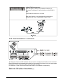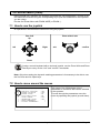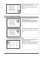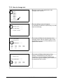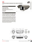
1
OPERATING INSTRUCTIONS CONTENTS 1 Introduction.............................................................................................................3 1.1 Contents of the package........................................................................................................3 1.2 The contents of this handbook...............................................................................................3 1.3 Typographical Conventions....................................................................................................3 2 Safety rules............................................................................................................4 3 Identification data...................................................................................................5 4 Installation..............................................................................................................5 4.1 Opening the package.............................................................................................................5 4.2 Checking the markings...........................................................................................................5 5 Assembly................................................................................................................6 5.1 Opening the base...................................................................................................................6 5.2 Attaching the support..............................................................................................................6 5.2.1 Attachment with bracket (optional).......................................................................................7 5.2.2 Attachment with a pole support (optional)............................................................................8 5.3 Assembling the camera, motorised lenses and accessories.................................................9 5.3.1 Camera assembling (only for model without camera module)..............................................9 5.3.1.1 Instructions for the HOV housing..................................................................................9 5.3.1.2 Instructions for the HEG housing................................................................................10 5.3.1.3 Connecting the camera and motorised lens...............................................................11 5.3.1.3.1 Connection board.........................................................................................................................11 5.3.1.3.2 Connector for camera/ motorised lenses.....................................................................................12 5.3.1.3.3 Adjusting the power supply voltage of the lens motors...............................................................13 5.3.2 Connecting the wiper..........................................................................................................14 5.3.2.1 Connecting the wiper inside the housing....................................................................14 5.3.3 Connecting the (washer) pump..........................................................................................15 5.3.4 Assembling the infrared spotlights (only for models designed for this)...............................16 5.3.4.1 Assembling the side supports.....................................................................................16 5.3.4.2 Changing the infrared support....................................................................................17 5.3.4.3 Assembling the spotlight on the side support.............................................................17 5.4 Wiring...................................................................................................................................19 5.4.1 Power supply......................................................................................................................19 5.4.2 Connecting the peripherals.................................................................................................20 5.5 Positioning the top unit.........................................................................................................21 5.6 Configuration........................................................................................................................22 5.6.1 Setting the baud rate..........................................................................................................22 5.6.2 Setting the protocol.............................................................................................................23 5.6.3 Setting the address.............................................................................................................23 5.6.4 Address table......................................................................................................................24 5.6.5 Serial communication lines.................................................................................................25 5.6.6 Serial terminations / connections........................................................................................27 6 Switching on and off.............................................................................................28 6.1 Before powering the device:.................................................................................................28 Page 1 of 57 MNVCUPT01_0703 7 On Screen Menu (OSM).......................................................................................29 7.1 How to use the joystick.........................................................................................................29 7.2 How to move around the menus..........................................................................................29 7.3 How to change the settings..................................................................................................30 7.3.1 How to change the numeric fields......................................................................................30 7.3.2 How to change text.............................................................................................................32 7.4 Configuring the system.........................................................................................................34 7.4.1 Main menu .........................................................................................................................34 7.4.2 Language...........................................................................................................................34 7.4.3 Screen management..........................................................................................................34 7.4.3.1 Area titling management.............................................................................................35 7.4.3.2 Display parameters.....................................................................................................36 7.4.4 Movement parameters........................................................................................................36 7.4.4.1 Speed.........................................................................................................................37 7.4.4.2 Limits..........................................................................................................................38 7.4.4.3 Movement parameters (preset, patrol, autopan).........................................................38 7.4.4.3.1 7.4.4.3.2 7.4.4.3.3 7.4.4.3.4 7.4.4.3.5 7.4.4.3.6 7.4.4.3.7 Preset...........................................................................................................................................39 Preset on screen menù................................................................................................................39 Special preset parameters...........................................................................................................40 Home............................................................................................................................................40 Patrol (cyclical loading of preset positions).................................................................................40 Autopan........................................................................................................................................41 Automatic loading of movements.................................................................................................41 7.4.5 Wiper..................................................................................................................................42 7.4.6 Alarms................................................................................................................................43 7.4.7 Loading the default values..................................................................................................44 7.4.8 Configuration info...............................................................................................................44 7.4.9 Integrated module parameter menu...................................................................................44 7.4.9.1 Zoom..........................................................................................................................45 7.4.9.2 Focus..........................................................................................................................45 7.4.9.3 Auto exposure.............................................................................................................46 7.4.9.4 Infrared.......................................................................................................................46 7.4.10 Dynamic masking.............................................................................................................47 7.4.10.1 How to create a new dynamic mask.........................................................................48 7.4.10.2 How to modify a dynamic mask that has already been inserted...............................50 7.4.11 Camera ZFI parameter menu...........................................................................................51 7.4.12 Areas masking..................................................................................................................52 7.4.13 Menu for deleting masks..................................................................................................53 8 Maintenance.........................................................................................................54 8.1 Cleaning................................................................................................................................54 8.2 Replacing the fuses..............................................................................................................54 9 Troubleshooting....................................................................................................55 10 Technical specifications.....................................................................................56 10.1 Dimensions and range of action.........................................................................................56 The manufacturer declines all responsibility for any damage caused by improper use of the appliances mentioned in this handbook; furthermore, the manufacturer reserves the right to change the contents without prior notice. All due care and attention has been given in gathering and checking the documentation contained in this manual: the manufacturer, however, cannot assume any liability arising from its use. The same also holds for any person or company concerned with the creation and production of this handbook. Page 2 of 57 MNVCUPT01_0703 1 Introduction 1.1 Contents of the package • • • • • 1 UPT device 1 bag of bolts and screws 1 user's handbook 1 serial extension cable 1 serial adapter When the product is delivered make sure the package is intact and has no obvious signs of dropping, scrapes or scratches. If the package is obviously damaged contact the supplier immediately. Make sure the contents correspond to the list of materials as above. 1.2 The contents of this handbook This handbook describes the UPT device and the specific procedures for installation, configuration and use. Read this handbook carefully before installing the device, paying particular attention to the section about safety rules. 1.3 Typographical Conventions This handbook makes use of different graphics symbols, the meaning of which is summarised as follows: Risk of electric shock; disconnect the power supply before proceeding with any operation, unless specified otherwise. This operation is very important for the system to function correctly: please read the procedure described carefully and carry it out as instructed. Mechanical hazard. Risk of crushing or shearing. Description of system specifications: we recommend reading this part carefully in order to understand the subsequent stages. Page 3 of 57 MNVCUPT01_0703 2 Safety rules The integrated positioning systems for video surveillance comprising the UPT line of devices comply with current legislation and standards in force at the time of publication of this handbook. Nevertheless, in order to ensure the user’s safety (installer technician and operator) the following warnings are specified in order to work in maximum safety: • The device must be installed and maintained only by skilled technical personnel. • Connect the device to a power source corresponding to the indications given on the marking label. • The device has been designed for permanent installation in a building or other suitable structure. • The device should be mounted so that it is accessible only to the technician/installer because the moving parts constitute a residual risk of injury caused by movement of said parts. • Before carrying out technical work on the appliance disconnect the power supply and disconnect the cables from other devices. • Do not use power cables with signs of wear or aging. • Do not use the appliance in the presence of inflammable substances. • Do not allow children or unauthorised people to use the appliance. • The appliance should only be considered switched OFF when the power supply has been disconnected and the connecting cables to other devices have been removed. • Keep this handbook carefully for future consultation. WARNING: This product must not be disposed of as normal refuse. The product must be disposed of according to the relevant legislation of the country where it is installed. For more detailed information about recycling this product, contact the local waste disposal service. Page 4 of 57 MNVCUPT01_0703 3 Identification data UPT pan & tilt devices have two labels complying with CE markings. The first label contains: • Model identification code (Extended 3/9 bar code) • Power supply voltage (Volt) • Frequency (Hertz) • Power consumption (Watt) The second label shows the serial number of the model (Extended 3/9 bar code) 4 Installation Installation work must only be carried out by skilled technical staff and the power supply should be disconnected unless indicated otherwise. 4.1 Opening the package If the package is not obviously damaged (due to dropping or abnormal scrapes and scratches), check the material inside it against the list given in the paragraph on Contents of the Package in the Introduction. The packaging materials are completely recyclable. The installer technician will be responsible for disposing of them by recycling or in compliance with the legislation in force in the country where the appliance is used. 4.2 Checking the markings Before proceeding further with installation, make sure the material supplied corresponds to the order specification by examining the marking labels as described in the section on Identification data. Never, under any circumstances, make any changes or connections that are not described in this handbook: the use of inappropriate appliances may expose personnel and the system to serious safety hazards. Page 5 of 57 MNVCUPT01_0703 5 Assembly To assemble or replace systems in the UPT line, it is necessary to carry out the following operations, which are illustrated in the following pages, in the order given: • • • • • • opening the base attaching the support assemble cameras, motorised lenses and accessories wiring up positioning the top unit configuration The appliance includes moving parts: make sure that the unit is positioned where it is inaccessible under normal operating conditions. 5.1 Opening the base Opening the base allows access to the connecting cables and to the pan & tilt power supply section. To open, see the illustration below. For further information also see section 5.5 Positioning the top unit, pag.21. WARNING: None of the other parts (except for the camera housing for models that are not supplied with a camera module) should be disassembled or tampered with, subject to invalidation of the guarantee. 5.2 Attaching the support WARNING: the device should be assembled vertically. Any other position could impair the performance of the appliance. Do not attach the device upside down. If using the Videotec washer kit (UPTWAS), the spray support should be installed before positioning the pan & tilt and the wiring. For further explanations see the specific handbook for the kit. Page 6 of 57 MNVCUPT01_0703 5.2.1 Attachment with bracket (optional) 1. 2. 3. 4. 5. 6. Bracket Base Screw Washer Screw ring Seal The bracket is drilled to make it easy the connection cables through it. The base can be attached to the wall bracket in 4 distinct positions, turning through 90° to each other, in order to facilitate positioning of the configuration board. To wire up the device proceed as follows: 1. insert the cables into the bracket so that they protrude by about half a metre 2. insert the cables into the cable glands and, holding the base at about 20 centimetres from the bracket, lock the cable glands 3. position the base on the bracket, guiding the cables so that they are positioned inside the bracket 4. fasten the base to the bracket with the screws 5. cut the cables to the correct length and make the connections. Page 7 of 57 MNVCUPT01_0703 5.2.2 Attachment with a pole support (optional) If using the Videotec washer kit (UPTWAS), the spray support should be installed before positioning the pan & tilt and the wiring. For further explanations, see the specific handbook for the kit. 1. 2. 3. 4. 5. 6. Support Base Screw Washer Screw ring Seal The pole support allows the passage of the connection cables. The base can be attached to the pole in 4 distinct positions, turning through 90° to each other, in order to facilitate positioning of the configuration board. To wire up the device proceed as follows: 1. Insert the cables into the support so that they protrude about half a metre 2. Insert the cables into the cable glands and, holding the base at about 20 centimetres from the bracket, lock the cable glands 3. Position the base on the support, passing the cables inside the support 4. Fasten the base to the support with the screws 5. Cut the cables to the correct length and make the connections. Page 8 of 57 MNVCUPT01_0703 5.3 Assembling the camera, motorised lenses and accessories The UPT pan&tilt is available with two different housing versions. For some models the customer is responsible for assembling the camera and the respective lenses. A number of optional accessories are also available to enable the product to operate to the full, such as lighting, washing system and infrared lighting. 5.3.1 Camera assembling (only for model without camera module) 5.3.1.1 Instructions for the HOV housing Fig. 2 Fig. 1 3 2 1 1. To open the housing, undo the two screws on the side (Fig. 1) and swivel the upper body until it is completely open (fig.2) 2. Take out the inner support slide (fig.2, detail 2), partially loosening the fastening screws (fig. 2, detail 1) 3. Move the slide along until the holes coincide with the slide locking screws. 4. Attach the camera using the 1/4" screw and adjust the internal slide so that the lens and camera are positioned correctly 5. Fasten down the adjustable slide in the correct position using the appropriate screw. When positioning the camera use also the spacers supplied for this purpose (fig. 2, detail 3). 6. Reposition the inner slide and tighten the screws that had been loosened previously. 7. Close the housing after making the necessary electrical connections Note: for some camera models it is necessary to insulate the camera case with respect to the attachment slide in order to prevent interference with the video signal. Page 9 of 57 MNVCUPT01_0703 5.3.1.2 Instructions for the HEG housing To open the housing, loosen the fastening screws (1,2,3) without removing them. Then undo the safety screws (dowels) on the side (4). Slide out the housing body (Fig.2) Assemble the camera and motorised lens using the plastic support (7) and the 1/4” screw (5) with its respective plastic washer (6). Page 10 of 57 MNVCUPT01_0703 5.3.1.3 Connecting the camera and motorised lens 5.3.1.3.1 Connection board The following is a description of the electronics board inside the housing, which controls all functions of the motorised lens. Description PTC1 PT1 COLD Connector for PTC heater Potentiometer for adjusting lens motor control voltage Heat exchanger fan control connector (not present on all models) HOT Heater fan control connector (not present on all models) CN1 BNC connector for connecting the video signal from the camera CN5 Power supply connector for wiper (power supply from base board via inputs F1 and F2 ) CN2/CN3 Connector for camera / motorised lenses Page 11 of 57 MNVCUPT01_0703 5.3.1.3.2 Connector for camera/ motorised lenses WARNING: all connections illustrated below should be made only and exclusively by expert installers who should comply with all the wiring and power supply specifications for the devices. The electronics board is designed to control cameras with motorised lenses (FOCUS, IRIS, ZOOM), which may or may not have potentiometers to control the position reached. Before making the connections make sure that the voltages supplied by the board fall within the limits allowed for the apparatus. Camera power supply +12V – 800mA max Lens potentiometer power supply +5V Lens motor power supply 6-15V (adjustable) – 200mA max (Focus+ Zoom+Iris) Make the connections as shown in the following diagram. Page 12 of 57 MNVCUPT01_0703 5.3.1.3.3 Adjusting the power supply voltage of the lens motors Before powering the pan & tilt, adjust the potentiometer to the minimum voltage value by turning it anticlockwise as far as it will go. Power the pan&tilt and after it has booted up, adjust the lens motor power supply voltage as necessary by increasing it or decreasing it. To check the actual voltage that will be applied to the focus, iris and zoom motors, measure the voltage over the points “lens+ e lens-” (points 2 and 3 in the illustration). If the value is incorrect, adjust it using the trimmer (point 1 in the illustration). Page 13 of 57 MNVCUPT01_0703 5.3.2 Connecting the wiper The pan & tilt may have a wiper, powered at 24VAc, with a maximum power of 18 Watt, and connected to the housing board. When the pan & tilt receives the command to start the wiper, contact “O1 – C1” closes for a given amount of time (which can be set in the corresponding OSM) (see § 7.4.5 - Wiper page 42), and the motors will start. At the end of the cleaning phase, the wiper will automatically stop in the rest position. The wiper connections are normally made when the pan & tilt is produced in the factory; for reference and for possible updates after purchasing the product, the instructions for connecting the wiper are given below. 5.3.2.1 Connecting the wiper inside the housing Wiper for HOV housing: WIPER Connect: With: X1 S(wiper board) X2 C1 C1 P(wiper board) O1 C(wiper board) M Wiper for HEG housing (Videotec code “VIP6A2”): WIPER Connect: With: X1 2(wiper connector) X2 C1 C1 3( wiper connector) O1 1( wiper connector) M WARNING:the power supply voltage of the wiper is 24V~(a.c.). Whenever you have to restore the connections take great care not to break the device or create risks to the operator. Page 14 of 57 MNVCUPT01_0703 5.3.3 Connecting the (washer) pump WARNING: the connections illustrated below should be made only and exclusively by skilled operatives who should comply scrupulously with all the wiring and power supply instructions. Failure to do so could create serious risks for the operator and would invalidate the guarantee. The diagram below refers to the 19-pin connector on the base board of the pan & tilt. All models in the UPT series have this function. The diagram shows: AL1 – alarm input, voltage-controlled (10-35V), to monitor the presence of water in the tank For devices with level sensors, closure of the contact, if enabled, generates an onscreen alarm O1-C1 – Clean contact for starting the water pump F1-F2 - Wiper power supply (max24Vac – 0.75A), from safety transformer housed in the base of the device. Connection with a washer system in the “UPTWAS” series The following instructions are for connecting Videotec “UPTWAS” systems, in the two UPTWAS01 and UPTWSA02 (5mt) and UPTWASA01 versions, at the different power supply voltages. N.B. to prevent faulty operation and device failure, follow the connection diagram below. NOTE: washer systems in the UPTWAS series, pump with 5 (mt) discharge head, do not have a level sensor. Hence, it is not necessary to connect the alarm input. Page 15 of 57 MNVCUPT01_0703 5.3.4 Assembling the infrared spotlights (only for models designed for this) For the UPT versions with HEG housing it is possible to fit 2 Videotec 300W IR300 series infrared spotlights. To fit them correctly proceed in the following order: • fit the side supports on the HEG housing • replace the assembly bracket of the infrared spotlight • assemble the spotlight on the side support • make the menu settings to disable a complete turn WARNING: for functional reasons, the infrared spotlights must both be assemble. 5.3.4.1 Assembling the side supports Insert the screws (1) with the washers (2) in the holes provided (3) on the side of the housing. Then insert the other two screws (4) in the corresponding holes. Make sure the support is firmly attached. Use only the material supplied with the kit. Page 16 of 57 MNVCUPT01_0703 5.3.4.2 Changing the infrared support Fig. A Fig. B The infrared spotlights in the IR300 series are supplied with a general bracket, like the one in Fig.A. In order to assemble the spots on the UPT, the bracket must be replaced with the one shown in Fig.B, specifically for the pan & tilt. Undo the screws (1) and the flat washer (2) on both sides of the support; keep the toothed washer on one side (4). Before assembling the bracket as in fig.B, insert the toothed washer between the bracket and the spotlight (Fig.2). Tighten the side screws (1), inserting the corresponding flat washer (2). 5.3.4.3 Assembling the spotlight on the side support Page 17 of 57 MNVCUPT01_0703 Move the spotlight sideways so as to slide it into the support. Tighten screw (1) and washer (2) so that the spotlight is securely fastened. Wire up the spotlight appropriately and make the onscreen menu settings to disable a complete turn by the pan & tilt (see § 7.4.4.2 - Limits, page 38). The IR spotlights connection to the power supply must be carry out by qualified personnel only. Folow with great care the instructions in the product handbook. During the normal operation the IR spotlight surface may overheat. Avoid direct contact and position the device far from not qualified personnel. Page 18 of 57 MNVCUPT01_0703 5.4 Wiring The appliance must only be wired up by skilled personnel. Keep a connection diagram for later consultation. Never for any reason whatsoever make any changes or connections that are not described in this handbook. Failure to respect the instructions in the handbook with regard to the connections may expose personnel and the system to serious safety hazards. Do not change the wiring already present in the product. Failure to respect this instruction may expose personnel and the system to serious safety hazards, and will invalidate the guarantee. Provide a suitably sized external bi-polar disconnecting switch. 5.4.1 Power supply The device is available in versions for different power supply voltages, the level of which is shown on the identification label for the product. Before proceeding with installation make sure the power supply specifications of the device coincide with those required. (e.g. Device at 24V, 230V or 120V). When connecting the base make sure the power supply is disconnected and the disconnecting switch is open. When the base is opened, the power supply board appears as below. Make the following connections. Power supply and bi-polar disconnecting switch Page 19 of 57 MNVCUPT01_0703 5.4.2 Connecting the peripherals The base has a 19-pin connector for which the following connections are illustrated: – RS485: serial communication lines, protocol and speed selected by the user – VIDEO: composite video OUT 1Vpp. – O1-C1 and O2-C2: clean output contacts that can be activated by alarm or by user (50V, 1A) – A1, A2, A3 and A4, alarm in, voltage-controlled (10/35VDC), referred to common COM. Page 20 of 57 MNVCUPT01_0703 5.5 Positioning the top unit WARNING:Apply a calibrated torque wrench setting of 2.1 Nm to the screws (3). Inside the bottom cover there is a small bag containing mineral salts that are used to prevent moisture formation in the base and near the connector boards. 1. Configuration window 2. Base 3. Screw 4. Screw seal 5. Base seal Attach the top unit (1) to the base (2) using the attachment screws (3), supplied with the corresponding seals (4). Make sure the base seal is present and in good condition(5). WARNING: there is only one way to anchor the base with the top part. Align the tabs on the sides to make sure the parts are positioned correctly. Page 21 of 57 MNVCUPT01_0703 5.6 Configuration Before powering the device it must be configured correctly by setting the DIP switches inside the configuration window. Open the window by undoing the screws as shown in the illustration: The following diagram represents the position of the DIP switches when the configuration window is opened at the top. Starting from the left, we see the baud rate selectors, the protocol selectors and the peripheral address selectors respectively. For all DIP switches when the rocker is down the switch is “OFF”, or represents the logical value “0”; when the rocker is up, on the other hand, the switch is “ON”, with logical value “1”. The white rectangle represents the position of the rocker. BAUD RATE PROTOCOL SERIAL + ADDRESS 5.6.1 Setting the baud rate DIP switches 4, 3 and 2 are used to set the communication rate of the device according to the table below. DIP switch No. 1 is used to update the firmware: “PROGRAM. ON” and “PROGRAM.OFF”. During normal use, make sure the rocker is “OFF” (PROGRAM. OFF). DIP-SWITCHES 4,3,2 (baud rate setting) DIP-SWITCH 1 (for updating the firmware) Page 22 of 57 MNVCUPT01_0703 5.6.2 Setting the protocol Video positioning systems with the UPT line can be controlled by a range of protocols. The following table shows the combinations for setting the protocol (central DIP switch, 8 rockers): Dip-switch Protocol Baud rate Parameters changing (OSM) Macro (Videotec) 300..38400 (8N 1) Specific control (Men+) Verify in control device Pelco D 300..38400 (8N 1) Preset 95 Sensormatic 300..38400 (8N 1) Standard combination (iris open + focus near or far + zoom wide) 5.6.3 Setting the address SERIAL LINES ADDRESS The UPT address can have a setting from 1 to 255. Binary code is used to select the address, using the 8 DIP switches at the top right. The up position represents binary value “1”, while the down position represents binary value “0”. All possible combinations are shown below (the white rectangle represents the position of the switch). Page 23 of 57 MNVCUPT01_0703 5.6.4 Address table 36 72 108 144 180 2 16 01 37 73 109 145 181 2 17 02 38 74 110 146 182 2 18 39 75 111 147 183 2 19 40 76 112 148 184 2 20 77 113 149 185 2 21 150 186 2 22 Non val ido 03 04 05 41 06 42 78 114 07 43 79 115 151 187 2 23 08 44 80 116 152 188 2 24 09 45 81 117 153 189 2 25 10 46 82 118 154 190 2 26 47 83 119 155 191 2 27 48 84 120 156 192 2 28 157 193 2 29 11 12 13 49 85 121 14 50 86 122 158 194 2 30 15 51 87 123 159 195 2 31 16 52 88 124 160 196 2 32 17 53 89 125 161 197 2 33 18 54 90 126 162 198 2 34 19 55 91 127 163 199 2 35 20 56 92 128 164 2 00 21 57 93 129 165 2 01 22 58 94 130 16 6 2 02 2 38 23 59 95 131 167 2 03 2 39 24 60 96 132 168 204 2 40 25 61 97 133 169 205 2 41 26 62 98 134 170 2 06 2 42 27 63 99 135 171 2 07 28 64 100 136 172 2 08 2 44 29 65 101 137 173 2 09 2 45 30 66 102 138 174 2 10 31 67 103 139 175 2 11 32 68 104 140 176 2 12 2 48 33 69 105 141 177 213 2 49 34 70 106 142 178 214 2 50 35 71 107 143 179 2 15 2 51 2 52 2 53 25 4 Page 24 of 57 2 36 2 37 2 43 2 46 2 47 255 MNVCUPT01_0703 5.6.5 Serial communication lines The product is designed with two RS485 serial communication lines and one RS232 serial line, which can have various settings according to the positions of DIP switches 10 and 9 on the “ SERIAL + ADDRESS” selector. RS485 line and RS232 line This setting is used to control the device via two different serial lines (for connecting the RS232 line, see § 5.6.6Serial terminations / connections, page 27) The first line (RS485-1) will operate according to the settings in the “ADDRESS”, ”BAUD RATE” and “PROTOCOL” DIP switch. The second line (RS232) is configured permanently with the MACRO protocol (baud:38400; 8bit, parity: N, stop bit:1). For connection use the connector and serial adapter supplied. The RS485-2 serial line is not used. Warning: the system is of the TNV-1 type, do not connect it to SELV circuits. 1 Page 25 of 57 MNVCUPT01_0703 RS422 connection (RS485-1 RX and RS485-2 TX) This setting allows full duplex communication according to the RS422 standard. This means that both the RS485-1 and RS485-2 lines are used. Note: this function is only available for bi-directional protocols (e.g. Pelco, Sensormatic, Macro, etc.). Line 1 RS485 and line 2 RS485 repetition With this type of setting it is possible to connect more than one device in cascade. The signal is regenerated by each unit, making it possible to markedly increase total distance. Limits: it only works with mono-directional protocols. 1 Page 26 of 57 MNVCUPT01_0703 RS485 TX/RX connection With this type of setting it is possible to obtain a bidirectional, half/duplex, communication on the RS485-1 line. The RS485-2 serial line is not used. Note: this function is only available for bi-directional protocols (e.g. Pelco, Sensormatic, Macro, etc.). 5.6.6 Serial terminations / connections The diagram shows two DIP switches that are used to configure termination of the serial line. Every peripheral that is situated at the end of a line must be terminated using the appropriate DIP switch in order to prevent signal reflection and distortion. DIP switches 1 and 2 terminate serial lines RS485-1 and RS485-2 respectively. Switch in the “ON” position = line terminated. Switch in the “OFF” position = line not terminated. Page 27 of 57 MNVCUPT01_0703 6 Switching on and off Systems in the UPT line are switched on by simply connecting the power supply, and switched off by disconnecting the power. 6.1 Before powering the device: Examine the identification labels to make sure that the material supplied corresponds with the order specifications, as described in the section “Identification data”. Make sure that the UPT system and other components of the installation are closed so that it is impossible to come into contact with live parts. Make sure that all parts are fastened down firmly and safely. Make sure that the power source and connecting cables are suitable for the power consumption of the system. Mechanical hazard. Risk of crushing or shearing. Do not stay in the vicinity of the device when it is powered. Always disconnect the power supply before working on the device. The first time the device is switched on we recommend making sure it is configured correctly. To do this, disconnect the power supply, remove the DIP switch protection window and set the firmware update DIP switch rocker to ON. Power the device and after a few seconds it will be possible to check the settings on the screen. After completing the check, switch off the device and re-toggle the firmware update DIP switch rocker to the down position (PROGRAM. OFF). Close the window and re-connect the power supply. Page 28 of 57 MNVCUPT01_0703 7 On Screen Menu (OSM) During normal UPT operation it is possible to activate the “On Screen Menu” in order to set the advanced functions using the corresponding key/s (see the handbook for the keyboard you are using). Exit the On Screen Menu with ZOOM WIDE (or ZOOM - ). 7.1 How to use the joystick All operations in the menus are carried out using the joystick. Pan & tilt Zoom wide & tele Up left Right exit confirm Down If using a control keyboard with a dual axis joystick, use the Zoom Wide and Zoom Tele keys to carry out the “exit” and “confirm” commands. Note: Only when setting the dynamic masking parameters is it necessary to be able to use the Iris Close and Iris Open keys. 7.2 How to move around the menus DISPLAY SETUP MENU ----------------------------1 – PAN/TILT POSITION : YES >2 - PRESET POSITION : YES 3 – PRESET TITLE : NO 4 – TILT LIMIT TITLE : NO 5 – VIDEO SIGNAL : PAL 6 – INTERLACED VIDEO : YES 7 – AREA PARAMETERS > 8 – DISPLAY PARAMETERS > Each page of the OSM shows a list of parameters or submenus that can be selected by the operator. To scroll through the parameters move the cursor by operating the joystick (up and down). Page 29 of 57 MNVCUPT01_0703 The symbol “>” at the end of a line indicates the presence of a specific submenu. To enter the submenu just confirm the menu item. To exit the submenu use the “exit” function (zoom out). DISPLAY SETUP MENU ----------------------------1 – PAN/TILT POSITION : YES 2 - PRESET POSITION : YES 3 – PRESET TITLE : NO 4 – TILT LIMIT TITLE : NO 5 – VIDEO SIGNAL : PAL 6 – INTERLACED VIDEO : YES 7 – AREA PARAMETERS > >8 – DISPLAY PARAMETERS > 7.3 How to change the settings DISPLAY SETUP MENU ----------------------------1 – PAN/TILT POSITION : YES >2 - PRESET POSITION : YES 3 – PRESET TITLE : NO 4 – TILT LIMIT TITLE : NO 5 – VIDEO SIGNAL : PAL 6 – INTERLACED VIDEO : YES 7 – AREA PARAMETERS > 8 – DISPLAY PARAMETERS > Move the cursor to the parameter to be changed and confirm. The field will start flashing, indicating that it is in change mode. Operating the joystick (up and down) will show the alternative choices. DISPLAY SETUP MENU ----------------------------1 – PAN/TILT POSITION : YES >2 - PRESET POSITION : NO 3 – PRESET TITLE : NO 4 – TILT LIMIT TITLE : NO 5 – VIDEO SIGNAL : PAL 6 – INTERLACED VIDEO : YES 7 – AREA PARAMETERS > 8 – DISPLAY PARAMETERS > After identifying the desired selection, confirm. The parameter will stop flashing to confirm the choice. 7.3.1 How to change the numeric fields AREA POSITION MENU ----------------------------1 - AREA 1 + 0,0 + 0,0 >2 - AREA 2 + 0,0 + 0,0 3 - AREA 3 + 0,0 + 0,0 4 - AREA 4 + 0,0 + 0,0 5 - AREA 5 + 0,0 + 0,0 6 - AREA 6 + 0,0 + 0,0 7 - AREA 7 + 0,0 + 0,0 8 - AREA 8 + 0,0 + 0,0 Move the cursor to the parameter to be changed, then confirm. The field/arrow will start to flash, indicating that it is in edit mode. Operating the joystick (up and down) will show the alternative choices. Text Area 1 Page 30 of 57 MNVCUPT01_0703 AREA POSITION MENU ----------------------------1 - AREA 1 + 0,0 + 0,0 2 - AREA 2 >+ 0,0 + 0,0 3 - AREA 3 + 0,0 + 0,0 4 - AREA 4 + 0,0 + 0,0 5 - AREA 5 + 0,0 + 0,0 6 - AREA 6 + 0,0 + 0,0 7 - AREA 7 + 0,0 + 0,0 8 - AREA 8 + 0,0 + 0,0 If there is more than one field on the same line it will be necessary to select the field by moving the joystick (left and right). After making the change, confirm. Text Area 1 AREA POSITION MENU ----------------------------1 - AREA 1 + 0,0 + 0,0 2 - AREA 2 >+000,0 + 0,0 3 - AREA 3 + 0,0 + 0,0 4 - AREA 4 + 0,0 + 0,0 5 - AREA 5 + 0,0 + 0,0 6 - AREA 6 + 0,0 + 0,0 7 - AREA 7 + 0,0 + 0,0 8 - AREA 8 + 0,0 + 0,0 The first digit in the numeric field to be changed will flash and the last line of the display will show the accepted limits for the field. Move in the field (left and right) and change the sign or the numeric value (up and down). >min:-180.00 max:+180.00 AREA POSITION MENU ----------------------------1 - AREA 1 + 0,0 + 0,0 >2 - AREA 2 +100,0 + 0,0 3 - AREA 3 + 0,0 + 0,0 4 - AREA 4 + 0,0 + 0,0 5 - AREA 5 + 0,0 + 0,0 6 - AREA 6 + 0,0 + 0,0 7 - AREA 7 + 0,0 + 0,0 8 - AREA 8 + 0,0 + 0,0 After making the change, confirm. The cursor returns to the left and the modified figure stops flashing. The field will be forced to the minimum or maximum allowed value if you try to insert a value outside the limits. >min:-180.00 max:+180.00 Page 31 of 57 MNVCUPT01_0703 7.3.2 How to change text TEXT AREA MENU ---------------------------->1 - AREA 1 2 - AREA 2 3 - AREA 3 4 - AREA 4 5 - AREA 5 6 - AREA 6 7 - AREA 7 8 - AREA 8 Move the cursor to the parameter to be changed, then confirm. MAIN ENTRANCE EDIT TEXT MENU ---------------------------->1 – STRING EDIT -------------------MAIN ENTRANCE -------------------- The text editing screen will appear. It is possible to delete the text directly or to edit it by re-confirming. 2 – DELETE STRING EDIT TEXT MENU ----------------------------1 – STRING EDIT v------------------MAIN ENTRANCE -------------------1ABC 5MNO 9YZ 2DEF 6PQR 0()* 3GHI 7STU +,-. 4JKL 8VWX EDIT TEXT MENU ----------------------------1 – STRING EDIT V------------------MAIN ENTRANCE ------------------->1ABC 5MNO 9YZ 2DEF 6PQR 0()* 3GHI 7STU +,-. The cursor will flash for the character to be changed. Move with the joystick (right or left) and position the cursor on the character to be edited, then confirm. The cursor will flash at the bottom of the screen, corresponding to the groups of characters. Use the joystick to position the cursor on the group containing the character to be added and then confirm. 4JKL 8VWX Page 32 of 57 MNVCUPT01_0703 EDIT TEXT MENU ----------------------------1 – STRING EDIT V------------------MAIN ENTRANCE ------------------->1ABC 5MNO 9YZ 2DEF 6PQR 0()* 3GHI 7STU +,-. The character being edited will flash and the joystick (up and down) can be used to change it. After making the change, confirm and continue to edit the text, or else refuse with esc. 4JKL 8VWX Page 33 of 57 MNVCUPT01_0703 7.4 Configuring the system 7.4.1 Main menu MAIN MENU ----------------------------1 - LANGUAGE 2 – DISPLAY SETUP 3 – CAMERA PARAMETERS 4 – LENS PARAMETERS 5 – LOAD DEFAULT CONFIG. 6 – SETUP INFO INFO From the main menu it is possible to enter menus for configuring the device. 7.4.2 Language LANGUAGE MENU ----------------------------1 - ITALIANO 2 - ENGLISH 3 - FRANCAIS 4 - DEUTSCH This menu is used to select and set the desired language. 7.4.3 Screen management DISPLAY SETUP MENU ----------------------------1 – PAN/TILT POSITION : YES 2 - PRESET POSITION : NO 3 – PRESET TITLE : NO 4 – TILT LIMIT TITLE : NO 5 – VIDEO SIGNAL : PAL 6 – INTERLACED VIDEO : YES 7 – AREA PARAMETERS > 8 – DISPLAY PARAMETERS > This menu is used to define settings for the information that will be displayed permanently on the screen, with respect to: Pan/Tilt position: shows the current position of the device (in degrees) with respect to the original position Preset position: indicating the preset number reached Preset indication: displays the message associated with the preset position Area indication: shows the area to which the device is pointing (see the section “area titling management”) indicates that tilt limits are reached type of video signal area titling management Page 34 of 57 MNVCUPT01_0703 7.4.3.1 Area titling management TEXT AREA MENU ----------------------------1 - AREA 1 2 - AREA 2 3 - AREA 3 4 - AREA 4 5 - AREA 5 6 - AREA 6 7 - AREA 7 8 - AREA 8 Text Area 1 AREA PARAMETERS MENU ----------------------------1 - AREAS - TITLE : N 2 - AREAS - TEXTS > 3 - AREAS - POSIT. > 8 – OFFSET PAN AREA POSITION MENU ----------------------------1 - AREA 1 + 0,0 + 0,0 2 - AREA 2 + 0,0 + 0,0 3 - AREA 3 + 0,0 + 0,0 4 - AREA 4 + 0,0 + 0,0 5 - AREA 5 + 0,0 + 0,0 6 - AREA 6 + 0,0 + 0,0 7 - AREA 7 + 0,0 + 0,0 8 - AREA 8 + 0,0 + 0,0 :+ 0.00 Text Area 1 This function enables a message on the screen depending on the horizontal position reached by the device. From this menu it is possible to enter two menus, up to 8 titles, used to set the text for each area and the start and end positions (in degrees). e.g. to activate the first title and obtain a message when the device is between 80° and 120°: Enter the “AREA POSITION” menu, enter the start and end settings for “AREA 1”. In the “AREA TEXT” menu, select the first line and enter the desired text. +/-180° 0° 120° 80° If the area position start and end values are set to zero this will disable text display. In case of superimposing of several areas, prevails that with lower numbering. Page 35 of 57 MNVCUPT01_0703 The OFFSET PAN parameter adds a corresponding value in degrees to the pan references used for displaying the titling. For example, if this value is set to +45°, all references will be shifted in PAN by +45° with respect to the system physical reference. 7.4.3.2 Display parameters The menu is used to set the parameters for the video titler, i.e. whole screen or superimposed mode, the background for the characters and text centring. DISPLAY PARAMETERS ----------------------------1 – OSD VIDEO ENABLING : N 2 – VIDEO CHARACTER TYPE: 000 3 – HORIZONTAL DELTA : 000 4 – VERTICAL DELTA : 000 5 – ADDRESS NR. : YES • • • • Video signal with OSD: if set to S it enables superimposed mode, otherwise the menu is displayed on the whole screen and the video signal from the camera is replaced by the background. Type of character on screen: 0 sets the background of the character to transparent, 1 to black. Horizontal/vertical delta: these set the position of reference of the titler, so that the text can be centred. Address No.: if enabled the top left of the screen will show the address number of the unit 7.4.4 Movement parameters MOTION PARAMETERS MENU ----------------------------1 - SPEED 2 - LIMITS 3 – PRESET/PATROL/AUTOPAN 4 - WIPER-WASHER 5 - ALARMS This menu is used to enter the settings menus for the device movement parameters. Page 36 of 57 MNVCUPT01_0703 7.4.4.1 Speed SPEED MENU ---------------------------1 - PAN 2 - TILT 3 - SPEED WITH ZOOM 4 - DIRECT.PROT.CONTROL PAN SPEED MENU ---------------------------1 - SPEED 1... 0,6 2 - SPEED 2... 1,0 3 - SPEED 3... 6,0 4 - SPEED 4... 10,0 5 - SPEED 5... 20,0 6 - SPEED 6... 30,0 7 - SPEED 7... 40,0 8 - DEFAULT TILT SPEED MENU ---------------------------1 - SPEED 1... 0,6 2 - SPEED 2... 1,0 3 - SPEED 3... 6,0 4 - SPEED 4... 10,0 5 - SPEED 5... 20,0 6 - SPEED 6... 30,0 7 - SPEED 7... 40,0 8 - DEFAULT The parameters shown at points 3 and 4 in the “SPEED MENU “ display are only shown if the function is available with the protocol in use and only if you are using a UPT model with SONY integrated lens module. For some UPT versions, for operating reasons, the maximum speed limits may be less than the absolute values. The following table shows the maximum speeds, depending on the UPT model in use: Max. pan speed Max. tilt speed Max. patrol / preset speed Max. ramp UPT with HOV / HEG 100 40 100 12 UPT with HEG+wiper 40 20 20 3 UPT with HEG+wiper+IR spotlights 40 20 20 3 In the “speed” menus it is possible to set the speed of the device after commands from the control device (keyboard or computer). The data are expressed as degrees per second. The values range from 0.1 to 100°/sec. The “speed with zoom” parameter -if enabled- automatically reduces the pan and tilt speed according to the selected zoom factor (only for versions with the Sony module). The “direct control by protocol” parameter enables pan & tilt speed management directly using the values from the protocol in use (only for Pelco and Sensormatic protocols). These protocols permit control of more speed levels than the seven default settings. Enabling this parameter will ignore the settings for pan & tilt speed (1 - PAN and 2 – TILT in the illustration). The speed values will therefore be divided between the minimum and maximum, according to the levels allowed by the protocol. Page 37 of 57 MNVCUPT01_0703 e.g. with the Pelco D protocol it is possible to manage up to 64 speed values. In this case 0 corresponds to a UPT speed of 0.01°/s and 64 to 40.0°/s. 7.4.4.2 Limits LIMITS MENU ----------------------------1 – ENABLE PAN LIM. : NO 2 – START PAN : + 0,00 3 – END PAN : + 0,00 4 – ENABLE TILT LIM.: NO 5 – START TILT : + 0,00 6 – END TILT : + 0,00 7 – COMPL. ROTATION : YES 8 – RAMP TYPE In this menu it is possible to set movement limits for the device. It is possible to set the following parameters: enabling limits and values in degrees taken by the device in pan & tilt. enable or disable complete rotation for scan/patrol/autopan movements (this function is useful when using accessories with external cables, such as infrared spotlights, where continuous rotation of the UPT could break the accessories themselves). The values are expressed in degrees and can range from -180.00° to +180.00° for pan and from -40.00° to +90.00° for tilt. The “complete rotation” parameter, moreover, enables the search for the shortest route during scan, patrol and autopan movements. The “ramp“ parameter is used to change start and stop times for the UPT. The higher the number, the greater the acceleration/deceleration during starting/stopping. 7.4.4.3 Movement parameters (preset, patrol, autopan) MOTION PARAMETERS MENU ----------------------------1 – PRESET > 2 – SPECIAL PRESET PARAM. > 3 – HOME POSITION > 4 – PATROL > 5 – AUTOPAN > 8 – MOTIONS RECALL > From this menu it is possible to set the movement parameters related to preset, patrol and autopan for the device. Page 38 of 57 MNVCUPT01_0703 7.4.4.3.1 Preset PRESET EDIT MENU ----------------------------PRST PAN : + 0,0 01 TILT : + 0,0 ENABLE: NO ZOOM : 00000 FOCUS : 00000 IRIS : 00000 SPEED : 040,0 DWELL : 00001 TXT:PRESET NR. 1 From this menu it is possible to set and change all the parameters for the available preset positions. It is possible to set the following parameters: pan & tilt position expressed in degrees enable preset zoom, focus and iris positions speed for reaching the position when the preset position is loaded by the patrol function dwell time in seconds during patrol and autopan movements the message displayed when the preset position is reached In this menu the preset values can be stored directly, by entering a submenu after confirming with the Iris Close command. 7.4.4.3.2 Preset on screen menù PRESET EDIT MENU - OSM ----------------------------1 – CHANGE PRESET 001 2 – RECALL PRESET In this menu it is possible to load the preset values already stored or to pass to the menu where the preset values can actually be set. PTZ MODE: MOVE CAMERA ----------------------------001 IRIS CLOSE -> ESC IRIS OPEN -> SAVE PRESET Move the pan and tilt to the desired position, then adjust the zoom and focus appropriately and confirm the settings using the IRIS OPEN command. Note: In this particular mode, the IRIS OPEN and IRIS CLOSE commands have no effect on the lenses. Page 39 of 57 MNVCUPT01_0703 7.4.4.3.3 Special preset parameters SPECIAL PRESET PARAM. MENU ----------------------------1 – PRESET SPEED REF.: 40,0 2 – SCAN SPEED : 40,0 3 – REDUCE TILT SPEED: 100 6 – PRESET DWELL TIME: 00000 7 – FORCE PRST DWELL T... NO 8 – FORCE PRST SPEED.... NO This menu can be used to make the following parameter settings: reference speed: this is the default value whenever a preset position is stored. scan speed: this is the reference speed used when a preset position is recalled by the “scan” function. Reduce the tilt speed to a percentage of pan (100% means no reduction). Force a preset dwell time: load all the preset values with the value present in the “Preset dwell time” parameter. Force a preset speed: load all the preset values with the value present in the “Preset speed reference”. 7.4.4.3.4 Home MENU HOME ----------------------------1 – HOME POSITION : 00001 2 – REACHED SPEED : 40,0 This menu is used to set the following parameters: “home” position: this is the preset position associated with the home function (in the example: preset No.1) speed for reaching the home position when it is loaded. 7.4.4.3.5 Patrol (cyclical loading of preset positions) PATROL MENU ----------------------------1 - START POSITION : 00001 2 - END POSITION : 00002 3 - FIRST PRST SPEED: 040,0 4 – RANDOM : YES This menu is used to set the following parameters: the first and last preset position considered valid for carrying out the “patrol” function. Page 40 of 57 MNVCUPT01_0703 the speed at which the UPT will reach the first preset position when the patrol function is activated. the “Random” parameter enables execution of the Patrol function by passing through the defined positions in a random manner. The random sequence is continually recalculated. 7.4.4.3.6 Autopan AUTOPAN MENU ----------------------------1 – START POSITION : 00001 2 – END POSITION : 00002 3 – REACH SPEED : 040,0 4 – FORWARD SPEED : 010,0 5 – REVERSE SPEED : 010,0 This menu is used to set the following parameters: the two preset positions to be reached: the initial position and the final position the speed for reaching the first preset position when the autopan function is loaded the speed when moving between the two preset positions 7.4.4.3.7 Automatic loading of movements MOTIONS RECALL MENU ----------------------------1 – TIME ENABLING : NO 2 – MOTION TYPE : HOME 3 – DWELL BEFORE ACT: 00050 It is possible to set up the UPT so that, after a given period of inactivity, it automatically carries out a movement setting made by the operator. This menu is used to set the following parameters: enabling the function select type of movement to be loaded (home, autopan or patrol) the interval for which the joystick is inactive before the movement setting is loaded. The delay time before loading is expressed in seconds. Page 41 of 57 MNVCUPT01_0703 7.4.5 Wiper For pan & tilt devices in the UPT line, it is possible to use a wiper and operate an (external) pump for cleaning the glass. As shown in the illustration, the spray for cleaning the glass is on the outside of the pan & tilt. For cleaning, the UPT must be positioned with the glass facing the spray, then start the pump for the glass cleaning liquid and start the wiper. It is therefore necessary to set a preset position corresponding to the spray and this will be loaded when the “wiper” function is started. For the Washer models fitted with a level sensor, the UPT is also able to display an onscreen message when the level of liquid in the tank is too low (only if using a pump with high discharge head from the UPTWASA series). WIPER-WASHER MENU ----------------------------1 - ENABLED : YES 2 – PRESET POSITION : 0001 3 – RELAYS NR. : 0002 4 – PUMP DELAY : 0000 5 – WIPER DURATION : 0010 6 – DELAY WIPER OFF : This menu is used to make the following settings: enable the “wiper” function the preset position to be reached which relay to activate for water pump control the delay between the pump command and when the wiper starts moving wiping time wiping time without water Page 42 of 57 MNVCUPT01_0703 7.4.6 Alarms TEST ALARMS MENU ----------------------------1 – ALARM 1 :OFF 2 – ALARM 2 :OFF 3 – ALARM 3 :OFF 4 – ALARM 4 :OFF ALARMS MENU ----------------------------1 – ALARM 1 2 – ALARM 2 3 – ALARM 3 4 – ALARM 4 5 – ALARMS TEST ALARM MENU ----------------------------1 - ACTION: : SCAN 2 - NR. : 1 3 4 – SHOW MESSAGE : SI 5 – DURATION : 00010 6 - TXT: ALARM TEXT This menu is used to make the following settings: enable action on alarm (scan, patrol, autopan, relay, manual IR filter enabling) the scan position to be reached or the number of the relay to be activated enable display of an alarm message length (in seconds) of alarm message display (0 means for the complete duration of the alarm) text associated with the alarm The test menu is used to verify alarm status. NOTE: the manual control option for the IR filter is only present in versions fitted with the Sony module. If selected, it means night mode will be enabled in the camera, corresponding to enabling of the corresponding alarm input. To be operative it is also necessary to set the parameters relating to infrared control mode (see 7.4.9.4 - Infrared, pag.46): INFRARED MODE ENABLING AUTOMATIC INFRARED MODE NO NO Connect the circuit to enable the IR spotlights, so that when they are powered the corresponding alarm input is enabled. In this way, every time the IR spots are switched on, the module automatically switches to night mode. Page 43 of 57 MNVCUPT01_0703 7.4.7 Loading the default values DEFAULT VALUES MENU ----------------------------1 – LOAD DEF. VALUES? : N ATTENTION!!! ALL PARAMETERS WILL BE DELETED This menu is used to restore all the parameter settings to the factory default values. WARNING: carrying out this operation will delete all previous settings (e.g. preset, patrol, autopan, home...). 7.4.8 Configuration info SETUP INFO MENU ----------------------------NET board : MPP board: ver. 1.3 ver. 1.3 Nov 04 2005 Nov 04 2005 Protocol : MACRO Baudrate : 38400 Address : 00001 Enabled RS485 TX-RX This menu is used to check the device configuration and the software versions of the UPT boards. 7.4.9 Integrated module parameter menu CAMERA MODULE PARAMETERS 1 2 3 4 5 6 7 – – – – – – - ZOOM FOCUS AUT EXPOSURE INFRARED DYNAMIC MASKING AREA MASKING VARIOUS From this menu it is possible to enter the submenus for configuring the parameters of the video module. WARNING: this menu and the associated submenus are only present in UPT models supplied with the SONY integrated lens module as standard. Page 44 of 57 MNVCUPT01_0703 7.4.9.1 Zoom ZOOM PARAMETERS MENU ----------------------------1 – MANUAL SPEED 007 2 – OPTICAL AND DIGIT NO This menu is used to make the following settings: zoom speed enable digital zoom The speed can take values between 0 (minimum speed) and 7, maximum speed. 7.4.9.2 Focus FOCUS PARAMETERS MENU ----------------------------1 – MANUAL SPEED 007 2 – AUTOFOCUS TYPE NORM 3 – SENSIBILITY LOW 4 – AUTOFOCUS ON This menu is used to make the following settings: focus speed type of autofocus sensitivity The speed can take values between 0 (minimum speed) and 7, maximum speed. Types of autofocus: 1. normal: standard operating mode for autofocus. We recommend this solution 2. interval: load the autofocus function at intervals. Loading is set at every 5 seconds 3. trigger: load autofocus whenever the zoom moves and automatic return to manual focus, after reaching the correct focus position. High and low sensitivity: 1. high: focusing at the higher speed. We recommend this solution 2. low: slower focusing. This is useful when the lighting is poor because it will make the image more stable. If AUTOFOCUS mode is set to ON, it is possible to load autofocus automatically whenever the zoom is moved or positioned, in accordance with the type of operation that has been selected. This function must be enabled whenever the control keyboard has no autofocus load button. Page 45 of 57 MNVCUPT01_0703 7.4.9.3 Auto exposure AE PARAMETERS ----------------------------1 – MODE: AUTOMATIC This menu is used to set: the type of exposure control. We recommend the “automatic” setting. Even though other settings are possible they make manual control difficult for the operator, using the Iris controls. 7.4.9.4 Infrared PARAMETERS MODE - INFRARED -----------------------------1 – INFRARED MODE ENABLING NO 2 – AUTOM. INFRARED MODE YES This menu is used to make the following settings: continuous activation of “infrared” mode enable the automatic function with automatic switching to “infrared” mode. The device will recognise the need to switch to infrared mode. This is the recommended choice. Page 46 of 57 MNVCUPT01_0703 7.4.10 Dynamic masking With dynamic masking it is possible to create up to 24 masks so as to hide specific areas defined by the user. The masks are defined in the space and take account of the horizontal, vertical and depth position of the zoom at the time of setting. The UPT will automatically hold the position and the size of the masking, according to the area displayed. It is possible to set up a maximum of 8 simultaneous masks. If the device is used at the maximum possible speed, video signal update times become critical and it will be necessary to create masks that are larger than the object to be hidden to be sure it will not be seen. PARAMETERS MODE - MASKING -----------------------------1 – MASK N. 2 – MASK CHANGING > 3 – POSITION RECALL 4 – CHANGING COLOUR YELLOW 5 – MASK COLOUR BLU 1.........2.... 123456789012345678901234 --x--------------------- PARAMETERS MODE - MASKING ----------------------------1 – MASKS CHANGING > 2 – MASKS DELETING > 001 PTZ MODE: MASKING PARAMETERS MODE - MASKING ----------------------------1 – DELETE ALL 2 – DELETE MASK 001 PARAMETERS MODE - MASKING -----------------------------1 – MASK N. 2 – MASK CHANGING > 3 – POSITION RECALL 4 – CHANGING COLOUR YELLOW 5 – MASK COLOUR BLU 1.........2.... 123456789012345678901234 --x--------------------- From this menu it is possible to: select the mask to be worked on enter the menu for creating/editing the mask load the position where the mask was defined choose the colour of the mask being modified choose the colour of the masks verify which masks have been enabled Page 47 of 57 MNVCUPT01_0703 7.4.10.1 How to create a new dynamic mask Select a free mask Enter the “Edit mask” menu In the following example we shall mask a flower. 001 Press the “Iris close” button to pass from “masking” mode to “move camera” mode 001 Operate the joystick on the keyboard to move the UPT and if necessary operate the zoom to centre the flower on the screen. 001 When the desired result is obtained press the “Iris open” button and turn the zoom to tele. 001 A small yellow rectangle will appear. Operate the joystick (pan & tilt) to enlarge the rectangle until it covers the whole flower. PTZ MODE: MASKING PTZ MODE: MOVE CAMERA PTZ MODE: MOVE CAMERA PTZ MODE: MASK CHANGING Page 48 of 57 MNVCUPT01_0703 001 When the desired result is obtained confirm by turning the zoom to tele A message will indicate that the mask has been saved. PTZ MODE: MASK CHANGING Page 49 of 57 MNVCUPT01_0703 7.4.10.2 How to modify a dynamic mask that has already been inserted Select the mask to be edited from the main menu Load the position Enter the “Edit mask” menu In the following example we shall modify a mask that is already present. The mask will appear coloured yellow. 001 Turn the zoom to tele to pass from “masking” mode to “edit mask” mode PTZ MODE: MASKING 001 Operate the joystick (pan & tilt) to enlarge or reduce the rectangle until the desired effect is obtained. PTZ MODE: MASK CHANGING 001 Confirm by turning the zoom to tele. A message will indicate that the mask has been saved. PTZ MODE: MASK CHANGING Page 50 of 57 MNVCUPT01_0703 7.4.11 Camera ZFI parameter menu ZFI CAMERA PARAMETERS ----------------------------1 - ZOOM/FOCUS/IRIS 2 – MASKING BY ZONES From the“CAMERA PARAMETERS” menu it is possible to enter the submenus for the parameter settings of the motorised camera. WARNING: this menu and the corresponding submenus are only present if you are using versions of the UPT without the integrated camera module. ZFI CAMERA PARAMETERS ----------------------------1 – ZOOM ENABLED : YES 2 – ZOOM WINDOW : 003 3 – FOCUS ENABLED : YES 4 – FOCUS WINDOW : 003 5 – IRIS ENABLED : YES 6 – IRIS WINDOW : 003 8 – LOAD DEFAULT VALUES In this menu it is possible to make the following settings: enabling zoom, focus and iris the intervention threshold for considering that the position has been reached The threshold values range from 3 to 10, they refer to the voltage reading on the potentiometers and should be chosen according to the motorised lens to be used. A lower value indicates less hysterisis tolerance when reading the stored positions, while a higher value will indicate a wider margin when reading the positions. The choice of best configuration should be based on the parameters of the device being used. Page 51 of 57 MNVCUPT01_0703 7.4.12 Areas masking MASKING MENAGEMENT MENU ----------------------------1 – MASK TEXT > 2 – MASK POSITION > AREAS MASKING TEXT MENU ----------------------------1 – MASK 1 2 - MASK 2 3 - MASK 3 4 - MASK 4 5 - MASK 5 6 - MASK 6 7 - MASK 7 8 - MASK 8 Text Mask 1 AREAS MASKING MENU ----------------------------1 – MASK 1 + 0,0 + 0,0 2 – MASK 2 + 0,0 + 0,0 3 – MASK 3 + 0,0 + 0,0 4 – MASK 4 + 0,0 + 0,0 5 – MASK 5 + 0,0 + 0,0 6 – MASK 6 + 0,0 + 0,0 7 – MASK 7 + 0,0 + 0,0 8 – MASK 8 + 0,0 + 0,0 Text Mask 1 From this menu it is possible to enter the menu for setting masking in zones. It is possible to activate up to 8 masks. From “AREAS MASKING TEXT MENU” it is possible to set the text of the masked area (see § 7.3.2 - How to change text, page 32). From “ AREAS MASKING MENU” it is possible to set the areas position: the dimensions on the submenu corresponds to the start (degrees) and to the end (degrees) of the choosen area. “0” - “0” disable the mask. +/-180° 0° 120° Page 52 of 57 80° MNVCUPT01_0703 7.4.13 Menu for deleting masks PARAMETERS MODE - MASKING ----------------------------1 – DELETE ALL 2 – DELETE MASK 001 This menu is used to: delete all created masks delete a single mask A message appears on the screen to confitm the operation is completed. Page 53 of 57 MNVCUPT01_0703 8 Maintenance 8.1 Cleaning UPT pan & tilt devices require no particular maintenance. To clean the device use neutral detergent and a non-abrasive cloth. Remember that the device is waterproof. 8.2 Replacing the fuses There are two preset fuses on the connection board. Their sizes are related to the power supply voltage, as shown in the table. Voltage Fuse F1 Fuse F2 24Vac 50/60Hz 6.3A aM - 250V 5x20 10A aM - 250V 5x20 120Vac 50/60Hz 6.3A aM - 250V 5x20 4A aM - 250V 5x20 230Vac 50/60Hz 6.3A aM - 250V 5x20 2A aM - 250V 5x20 Page 54 of 57 MNVCUPT01_0703 9 Troubleshooting Problem: the device is switched off and shows no signs of life. Possible causes: incorrect wiring, fuses blown. Solution: make sure all the connections are correct, check the continuity of the fuses and, if there is a failure, replace them according to the values shown in the table. NOTE: if the fuses blow repeatedly, contact the authorised service centre. Problem: there is no image on the screen, just a blue screen with the message NO VIDEO SIGNAL!!!. Possible causes: incorrect camera or module wiring, camera failure. Solution: make sure all connections are correct for the version with camera and motorised lenses. For the version with the Sony module, contact the authorised service centre. Problem: the preset positions do not correspond with the area shown by the camera. Possible causes: reference for absolute position lost. Solution: carry out the dome calibration procedure from the keyboard (see the corresponding handbook) or reset the apparatus by switching it off and on again. Problem: under particular zoom conditions the housing or sunshield interferes with the image (only for versions with motorised lens). Possible causes: the camera is too far behind the glass. Solution: adjust the camera position by adjusting the slide until the correct position is found. Problem: the monitor does NOT show the image photographed by the UPT, but shows a display similar to: ----------------------------NET board :MPP board ver. 1.0 ver. 1.0 Jul 26 2005 Jul 26 2005 Protocol :MACRO Baudrate :38400 Address :00001 Enabled RS232 >Dip-switch upgrade to 1 Possible causes: programming dip switch on (up). Solution: switch off the pan & tilt, switch off (down) the “PROGRAM.” dip switch (dip-switch number 1 in the baud rate section) and then switch the device on again. Page 55 of 57 MNVCUPT01_0703 10 Technical specifications Horizontal movement (Pan) Continuous rotation Vertical movement (Tilt) +90° / -40° Horizontal speed Variable from 0.1°/s to 100°/s Vertical speed Variable from 0.1°/s to 40°/s Operating temperature: From -20°C to +40°C Power supply: 230V~ 50/60Hz 120V~ 50/60Hz 24V~ 50/60Hz Paint RAL9002 with epoxy powder Construction Die-cast aluminium, outer body in ABS Protection IP66 Weight 14kg Dimensions: 258x584x514mm (W x H x D) 10.1 Dimensions and range of action Page 56 of 57 MNVCUPT01_0703 Page 57 of 57 MNVCUPT01_0703