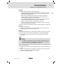
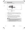
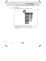
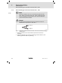
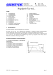
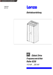
1
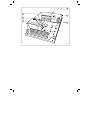
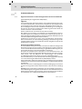
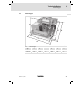
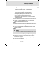
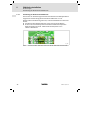
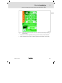
Ä.=A7ä EDB712 .=A7 Betriebsanleitung Operating Instructions 712 L 712 E.3B Spannungssteller Voltage controller Lesen Sie zuerst diese Anleitung, bevor Sie mit den Arbeiten beginnen! Please read these instructions before you start working! Beachten Sie die enthaltenen Sicherheitshinweise. Follow the enclosed safety instructions. 4 1 5 2 3 L 6 712_000 Funktionselemente: Bauteilkennzeichnung Bauteilbezeichnung Bestückungsplätze R101 - R103 zur Netzanpassung Elektroniksicherung Leistungsanschlüsse Steuerklemmen Trimmer für Umax, Umin und UTänzer Drahtbrücke zur Netzanpassung Diese Dokumentation ist gültig für ... ... Spannungssteller 712 ab der Typenschildbezeichnung: 712 _ E 3x Produktreihe Spannungssteller 712 712 = 6.6 kW Ausführung E= Einbaugerät Hardwarestand x= B EDB712 DE/EN 2.1 5 Dokumenthistorie Materialnummer Version Beschreibung !GôD n. def. 12/1992 TD00 !GôD n. def. 05/1996 TD00 Komplette Überarbeitung 13148242 1.0 09/2006 TD03 Komplette Überarbeitung .=A7 2.0 12/2008 TD29 Neuauflage wegen Neuorganisation des Unternehmens 2.1 03/2010 TD00 Neue Adresse 0Abb. 0Tab. 0 Tipp! Dokumentationen und Software-Updates zu weiteren Lenze Produkten finden Sie im Internet im Bereich ”Services & Downloads” unter http://www.Lenze.com 6 EDB712 DE/EN 2.1 Inhalt i 1 Vorwort und Allgemeines . . . . . . . . . . . . . . . . . . . . . . . . . . . . . . . . . . . . . . . . . . 9 2 Sicherheitshinweise . . . . . . . . . . . . . . . . . . . . . . . . . . . . . . . . . . . . . . . . . . . . . . . 10 2.1 Allgemeine Sicherheits- und Anwendungshinweise für Lenze-Antriebssteller . . . . . . . . . . . . . . . . . . . . . . . . . . . . . . . . . . . . . . . . Restgefahren . . . . . . . . . . . . . . . . . . . . . . . . . . . . . . . . . . . . . . . . . . . . . . Definition der verwendeten Hinweise . . . . . . . . . . . . . . . . . . . . . . . . . . 10 13 14 Technische Daten . . . . . . . . . . . . . . . . . . . . . . . . . . . . . . . . . . . . . . . . . . . . . . . . . 15 3.1 3.2 3.3 Allgemeine Daten und Einsatzbedingungen . . . . . . . . . . . . . . . . . . . . . Bemessungsdaten . . . . . . . . . . . . . . . . . . . . . . . . . . . . . . . . . . . . . . . . . . Abmessungen . . . . . . . . . . . . . . . . . . . . . . . . . . . . . . . . . . . . . . . . . . . . . . 15 16 17 Mechanische Installation . . . . . . . . . . . . . . . . . . . . . . . . . . . . . . . . . . . . . . . . . . . 18 4.1 Wichtige Hinweise . . . . . . . . . . . . . . . . . . . . . . . . . . . . . . . . . . . . . . . . . . 18 Elektrische Installation . . . . . . . . . . . . . . . . . . . . . . . . . . . . . . . . . . . . . . . . . . . . . 19 5.1 Wichtige Hinweise . . . . . . . . . . . . . . . . . . . . . . . . . . . . . . . . . . . . . . . . . . 5.1.1 FI-Schutzschalter . . . . . . . . . . . . . . . . . . . . . . . . . . . . . . . . . 5.1.2 Elektrostatische Gefährdung . . . . . . . . . . . . . . . . . . . . . . . . 5.1.3 Abschirmung . . . . . . . . . . . . . . . . . . . . . . . . . . . . . . . . . . . . . 5.1.4 Erdschluss vermeiden . . . . . . . . . . . . . . . . . . . . . . . . . . . . . . 5.1.5 Netzpotenzial . . . . . . . . . . . . . . . . . . . . . . . . . . . . . . . . . . . . 5.1.6 Sollwertpotenziometer . . . . . . . . . . . . . . . . . . . . . . . . . . . . 5.1.7 Schaltspitzenreduktion . . . . . . . . . . . . . . . . . . . . . . . . . . . . EMV-gerechte Installation . . . . . . . . . . . . . . . . . . . . . . . . . . . . . . . . . . . . 5.2.1 Komponenten des CE-typischen Antriebssystems . . . . . . . 5.2.2 Installation des CE-typischen Antriebssystem . . . . . . . . . . Anschlussplan . . . . . . . . . . . . . . . . . . . . . . . . . . . . . . . . . . . . . . . . . . . . . 5.3.1 Antriebssteller Typ 712 für Netzanschluss 340 ... 460 V . . . 5.3.2 Antriebssteller Typ 712 für Netzanschluss 190 ... 265 V . . 5.3.3 Anschluss von Steuersignalen an den Antriebssteller 712 5.3.4 Erweiterung des Drehmomentstellbereichs . . . . . . . . . . . . 19 19 19 20 20 20 20 20 21 21 22 25 25 26 29 30 Inbetriebnahme . . . . . . . . . . . . . . . . . . . . . . . . . . . . . . . . . . . . . . . . . . . . . . . . . . 31 6.1 6.2 31 32 2.2 2.3 3 4 5 5.2 5.3 6 EDB712 DE/EN 2.1 Wichtige Hinweise . . . . . . . . . . . . . . . . . . . . . . . . . . . . . . . . . . . . . . . . . . Erstinbetriebnahme . . . . . . . . . . . . . . . . . . . . . . . . . . . . . . . . . . . . . . . . 7 i Inhalt 7 Wartung/Reparatur . . . . . . . . . . . . . . . . . . . . . . . . . . . . . . . . . . . . . . . . . . . . . . . 33 8 Anhang . . . . . . . . . . . . . . . . . . . . . . . . . . . . . . . . . . . . . . . . . . . . . . . . . . . . . . . . . 34 8.1 34 8 Zubehör . . . . . . . . . . . . . . . . . . . . . . . . . . . . . . . . . . . . . . . . . . . . . . . . . . . EDB712 DE/EN 2.1 Vorwort und Allgemeines 1 1 Vorwort und Allgemeines Mit dem Spannungssteller 712lassen sich Drehstromasynchronmotoren mit Widerstandsläuferverhalten bis zu einer Leistung von 3.3 kVA stufenlos im Drehmoment stellen. Das Drehmoment wird beeinflusst über eine Veränderung des Schlupfes durch Phasenanschnittsteuerung der Ständerspannung. Dieser Spannungssteller stimmt mit geltenden EG-Richtlinien überein und eignet sich zum Aufbau von CE-konformen Antriebssystemen. Folgende Ausstattungsmerkmale und Eigenschaften dieses Spannungsstellers ermöglichen einen sicheren und störungsfreien Motorantrieb: A Kompaktes Zweiplatinengerät mit potenzialfreier Kühlplatte B Großer Stellbereich der Ausgangsspannung bis zur vollen Netzspannung C Anschluss des Mittelpunkt- oder Sternpunktleiters für Stellbereiche bis 1:20 nicht erforderlich D Für Wickelanwendungen ist ein zweiter Sollwerteingang zum Anschluss eines Tänzerpotentiometers vorhanden E Durch einfache Umbestückung zwei Netzspannungsbereiche wählbar F Bedingt kurzschlussfest G Schutzart IP 00 Hinweis! ƒ In der Betriebsanleitung werden die Spannungssteller nachfolgend Antriebssteller genannt. ƒ Querverweise innerhalb der Betriebsanleitung sind gekennzeichnet mit: ( ) EDB712 DE/EN 2.1 9 2 Sicherheitshinweise 2 Sicherheitshinweise 2.1 Allgemeine Sicherheits- und Anwendungshinweise für Lenze-Antriebssteller Allgemeine Sicherheits- und Anwendungshinweise für Lenze-Antriebssteller (gemäß Niederspannungsrichtlinie 2006/95/EG) Allgemein Lenze-Antriebssteller (Spannungssteller) und zugehörige Komponenten können während des Betriebs - ihrer Schutzart entsprechend - spannungsführende, auch bewegliche oder rotierende Teile haben. Oberflächen können heiß sein. Bei unzulässigem Entfernen der erforderlichen Abdeckung, bei unsachgemäßem Einsatz, bei falscher Installation oder Bedienung besteht die Gefahr von schweren Personen- oder Sachschäden. Weitere Informationen entnehmen Sie der Dokumentation. Alle Arbeiten zum Transport, zur Installation, zur Inbetriebnahme und zur Instandhaltung darf nur qualifiziertes Fachpersonal ausführen (IEC 364 bzw. CENELEC HD 384 oder DIN VDE 0100 und IEC-Report 664 oder DIN VDE 0110 und nationale Unfallverhütungsvorschriften beachten). Qualifiziertes Fachpersonal im Sinne dieser grundsätzlichen Sicherheitshinweise sind Personen, die mit Aufstellung, Montage, Inbetriebsetzung und Betrieb des Produkts vertraut sind und die über die ihrer Tätigkeit entsprechenden Qualifikationen verfügen. Bestimmungsgemäße Verwendung Antriebssteller sind Komponenten, die zum Einbau in elektrische Anlagen oder Maschinen bestimmt sind. Sie sind keine Haushaltsgeräte, sondern als Komponenten ausschließlich für die Verwendung zur gewerblichen Nutzung bzw. professionellen Nutzung im Sinne der EN 61000-3-2 bestimmt. Bei Einbau der Antriebssteller in Maschinen ist die Inbetriebnahme (d. h. die Aufnahme des bestimmungsgemäßen Betriebs) solange untersagt, bis festgestellt wurde, dass die Maschine den Bestimmungen der EG-Richtlinie 2006/42/EG (Maschinenrichtlinie) entspricht; EN 60204 beachten. Die Inbetriebnahme (d. h. die Aufnahme des bestimmungsgemäßen Betriebs) ist nur bei Einhaltung der EMV-Richtlinie (2004/108/EG) erlaubt. Die Antriebssteller erfüllen die Anforderungen der Niederspannungsrichtlinie 2006/95/EG. Die harmonisierte Norm EN 61800-5-1 wird für die Antriebssteller angewendet. Die technischen Daten und die Angaben zu Anschlussbedingungen entnehmen Sie dem Leistungsschild und der Dokumentation. Halten Sie diese unbedingt ein. Warnung: Die Antriebssteller sind Produkte, die nach EN 61800-3 in Antriebssysteme der Kategorie C2 eingesetzt werden können. Diese Produkte können im Wohnbereich Funkstörungen verursachen. In diesem Fall kann es für den Betreiber erforderlich sein, entsprechende Maßnahmen durchzuführen. 10 EDB712 DE/EN 2.1 Sicherheitshinweise Allgemeine Sicherheits- und Anwendungshinweise für Lenze-Antriebssteller 2 Transport, Einlagerung Beachten Sie die Hinweise für Transport, Lagerung und sachgemäße Handhabung. Halten Sie die klimatischen Bedingungen ein (siehe ggf. Kapitel ”Technische Daten”). Aufstellung Sie müssen die Antriebssteller nach den Vorschriften der zugehörigen Dokumentation aufstellen und kühlen. Sorgen Sie für sorgfältige Handhabung und vermeiden Sie mechanische Überlastung. Verbiegen Sie bei Transport und Handhabung weder Bauelemente noch ändern Sie Isolationsabstände. Berühren Sie keine elektronischen Bauelemente und Kontakte. Antriebssteller enthalten elektrostatisch gefährdete Bauelemente, die Sie durch unsachgemäße Handhabung leicht beschädigen können. Beschädigen oder zerstören Sie keine elektrischen Komponenten, da Sie dadurch Ihre Gesundheit gefährden können! Elektrischer Anschluss Beachten Sie bei Arbeiten an unter Spannung stehenden Antriebsstellern die geltenden nationalen Unfallverhütungsvorschriften (z. B. VBG 4). Führen Sie die elektrische Installation nach den einschlägigen Vorschriften durch (z. B. Leitungsquerschnitte, Absicherungen, Schutzleiteranbindung). Zusätzliche Hinweise enthält die Dokumentation. Die Dokumentation enthält Hinweise für die EMV-gerechte Installation (Schirmung, Erdung, Anordnung von Filtern und Verlegung der Leitungen). Beachten Sie diese Hinweise ebenso bei CE-gekennzeichneten Antriebsstellern. Der Hersteller der Anlage oder Maschine ist verantwortlich für die Einhaltung der im Zusammenhang mit der EMV-Gesetzgebung geforderten Grenzwerte. Um die am Einbauort geltenden Grenzwerte für Funkstöraussendungen einzuhalten, müssen Sie die Antriebssteller in Gehäuse (z. B. Schaltschränke) einbauen. Die Gehäuse müssen einen EMV-gerechten Aufbau ermöglichen. Achten Sie besonders darauf, dass z. B. Schaltschranktüren möglichst umlaufend metallisch mit dem Gehäuse verbunden sind. Öffnungen oder Durchbrüche durch das Gehäuse auf ein Minimum reduzieren. Lenze-Antriebssteller können einen Gleichstrom im Schutzleiter verursachen. Wird für den Schutz bei einer direkten oder indirekten Berührung ein Differenzstromgerät (RCD) verwendet, ist auf der Stromversorgungsseite des Antriebsstellers nur ein Differenzstromgerät (RCD) vom Typ B zulässig. Anderenfalls muss eine andere Schutzmaßnahme angewendet werden, wie z. B. Trennung von der Umgebung durch doppelte oder verstärkte Isolierung oder Trennung vom Versorgungsnetz durch einen Transformator. EDB712 DE/EN 2.1 11 2 Sicherheitshinweise Allgemeine Sicherheits- und Anwendungshinweise für Lenze-Antriebssteller Betrieb Sie müssen Anlagen mit eingebauten Antriebsstellern ggf. mit zusätzlichen Überwachungs- und Schutzeinrichtungen gemäß den jeweils gültigen Sicherheitsbestimmungen ausrüsten (z. B. Gesetz über technische Arbeitsmittel, Unfallverhütungsvorschriften). Sie dürfen die Antriebssteller an Ihre Anwendung anpassen. Beachten Sie dazu die Hinweise in der Dokumentation. Nachdem der Antriebssteller von der Versorgungsspannung getrennt ist, dürfen Sie spannungsführende Geräteteile und Leistungsanschlüsse nicht sofort berühren, weil Kondensatoren aufgeladen sein können. Beachten Sie dazu die entsprechenden Hinweisschilder auf dem Antriebssteller. Halten Sie während des Betriebs alle Schutzabdeckungen und Türen geschlossen. Hinweis für UL-approbierte Anlagen mit eingebauten Antriebsstellern: UL warnings sind Hinweise, die nur für UL-Anlagen gelten. Die Dokumentation enthält spezielle Hinweise zu UL. Wartung und Instandhaltung Die Antriebssteller sind wartungsfrei, wenn die vorgeschriebenen Einsatzbedingungen eingehalten werden. Bei verunreinigter Umgebungsluft können die Kühlflächen des Antriebsstellers verschmutzen oder Kühlöffnungen verstopft werden. Bei diesen Betriebsbedingungen deshalb regelmäßig die Kühlflächen und Kühlöffnungen reinigen. Dazu niemals scharfe oder spitze Gegenstände verwenden! Entsorgung Metalle und Kunststoffe zur Wiederverwertung geben. Bestückte Leiterplatten fachgerecht entsorgen. Beachten Sie unbedingt die produktspezifischen Sicherheits- und Anwendungshinweise in dieser Anleitung! 12 EDB712 DE/EN 2.1 Sicherheitshinweise Restgefahren 2.2 2 Restgefahren Personenschutz Antriebssteller haben die Schutzart IP 00. Alle spannungsführenden Teile sind frei zugänglich. ƒ Decken Sie spannungsführende Teile ab. Dadurch verhindern Sie den unbeabsichtigten Kontakt mit lebensgefährlichen Spannungen. ƒ Schalten Sie das Netz ab, bevor Sie am Antriebssteller arbeiten. ƒ Überprüfen Sie vor Arbeiten am Antriebssteller, ob alle Klemmen spannungslos sind. Motorschutz ƒ Bei längerem Betrieb eigenbelüfteter Motoren mit kleinen Drehzahlen kann der Motor überhitzt werden. ƒ Setzen Sie zum Schutz gegen gefährliche Überdrehzahlen zusätzliche Komponenten ein. EDB712 DE/EN 2.1 13 2 Sicherheitshinweise 2.3 Definition der verwendeten Hinweise Definition der verwendeten Hinweise Um auf Gefahren und wichtige Informationen hinzuweisen, werden in dieser Dokumentation folgende Piktogramme und Signalwörter verwendet: Sicherheitshinweise Aufbau der Sicherheitshinweise: Gefahr! (kennzeichnet die Art und die Schwere der Gefahr) Hinweistext (beschreibt die Gefahr und gibt Hinweise, wie sie vermieden werden kann) Piktogramm und Signalwort Bedeutung Gefahr! Gefahr von Personenschäden durch gefährliche elektrische Spannung Hinweis auf eine unmittelbar drohende Gefahr, die den Tod oder schwere Verletzungen zur Folge haben kann, wenn nicht die entsprechenden Maßnahmen getroffen werden. Gefahr! Gefahr von Personenschäden durch eine allgemeine Gefahrenquelle Hinweis auf eine unmittelbar drohende Gefahr, die den Tod oder schwere Verletzungen zur Folge haben kann, wenn nicht die entsprechenden Maßnahmen getroffen werden. Stop! Gefahr von Sachschäden Hinweis auf eine mögliche Gefahr, die Sachschäden zur Folge haben kann, wenn nicht die entsprechenden Maßnahmen getroffen werden. Anwendungshinweise Piktogramm und Signalwort 14 Bedeutung Hinweis! Wichtiger Hinweis für die störungsfreie Funktion Tipp! Nützlicher Tipp für die einfache Handhabung Verweis auf andere Dokumentation EDB712 DE/EN 2.1 Technische Daten Allgemeine Daten und Einsatzbedingungen 3 Technische Daten 3.1 Allgemeine Daten und Einsatzbedingungen Konformität CE Verschmutzungsgrad VDE 0110 Teil 2, Verschmutzungsgrad 2 Klimatische Bedingungen nach EN 60721-3-1 bis 60721-3-4 (ohne Betauung, mittlere relative Feuchte 85 %) Lagerung 1K2 nach IEC/EN 60721-3-1 Temperatur Transport Niederspannungsrichtlinie (2006/95/EG) EMV-Richtlinie (2004/108/EG) 0 °C ... +45 °C 2K2 nach IEC/EN 60721-3-2 Temperatur Betrieb 0 °C ... +45 °C 3K3 nach IEC/EN 60721-3-3 Temperatur 0 °C ... +45 °C Bei Betriebs-Umgebungstemperaturen Die Umgebungstemperatur darf +45 °C nicht überschreiten. Einbaulagen Senkrecht an einer Wand, Klemmen nach unten. Einbaufreiräume ( 18) Ableitstrom gegen PE (nach EN 61800-5-1) < 3.5 mA Schutzart IP 00 Isolationsfestigkeit Überspannungskategorie III nach VDE 0110 mechanische Festigkeit VDE 0160 (Schwingprüfung) EDB712 DE/EN 2.1 3 15 3 Technische Daten 3.2 Bemessungsdaten Bemessungsdaten Antriebssteller - Baureihe 712 Ausgangsleistung (bezogen auf 380 V-Netzspannung) Ausgangsstrom (Dauereffektivstrom) Typ 712 E.3B Pel [kW] 6.6 I [A] 3 x 10 Netzfrequenz f [Hz] 50/60 Netzspannung UL1, L2, L3 U [V] 190...265 1) 340...460 2) min. Spannung Umin / Unetz [V] 0 ... 0.25 max. Spannung Umax / Unetz [V] 0.5 ... 1 ULN [V] 10 R1 10 kΩ / 1Wlin Nenn-Leitspannung Sollwertpotenziometer Daten Art.-Nr. 322 194 Absicherung Leistungsteil Daten 3 Stück FF 16 A (6.3 x 32 mm), superflink Art.-Nr. 305 725 Absicherung Elektronik Daten M 0.1 (5 x 20 mm), mittelträge Art.-Nr. Masse ca. 305 704 m [kg] 1 umstellbar durch manuelle Veränderungen ( 2 Lenze-Einstellung 16 0.6 26) EDB712 DE/EN 2.1 Technische Daten 3 Abmessungen 3.3 Abmessungen e d b Æ c a 712_001 Abb. 1 Abmessungen Typ 712 E.3B EDB712 DE/EN 2.1 a b c d e ∅ (mm) (mm) (mm) (mm) (mm) (mm) 115 170 100 160 60 4 17 4 Mechanische Installation 4 Mechanische Installation 4.1 Wichtige Hinweise Wichtige Hinweise Die Umgebungstemperatur um die Antriebssteller darf + 45°C nicht überschreiten. ƒ Sorgen Sie für ausreichende Belüftung, wenn Sie den Antriebssteller in ein Gehäuse einbauen. ƒ Montieren Sie den Antriebssteller senkrecht mit den Klemmen nach unten. Gefahr! Gefährliche elektrische Spannung Externe Schalter und Sicherungen müssen vom Antriebssteller mindestens 250 mm entfernt sein. Verhindern Sie unbeabsichtigtes Berühren spannungsführender Teile, wenn Sie diesen Mindestabstand konstruktionsbedingt unterschreiten. ƒ Montieren Sie eine geeignete Abdeckung, die unbeabsichtigtes Berühren der Geräteplatine ausschließt. 18 EDB712 DE/EN 2.1 Elektrische Installation Wichtige Hinweise FI-Schutzschalter 5 Elektrische Installation 5.1 Wichtige Hinweise 5.1.1 FI-Schutzschalter 5 Gefahr! Gefährliche elektrische Spannung Antriebssteller dieser Baureihe verfügen über einen internen Netzgleichrichter. Nach einem Körperschluss kann deshalb ein Fehlergleichstrom die Fehlerstromauslösung blockieren. Um das zu verhindern, treffen Sie folgende Maßnahmen: ƒ Nullen Sie die Anlage oder verwenden Sie allstromsensitive FI-Schutzschalter. Betriebsmäßig auftretende kapazitive Ausgleichsströme der Leitungsschirme und der Entstörfilter können zu einer Fehlauslösung beim FI-Schutzschalter führen. ƒ Stellen Sie den Auslösestrom des FI-Schutzschalter so hoch ein, dass eine Fehlauslösung nicht möglich ist. 5.1.2 Hinweis! Allstromsensitive FI-Schutzschalter werden in den Normen DIN EN 61800-5-1 und IEC 755 beschrieben. Elektrostatische Gefährdung Stop! Elektrostatische Gefährdung Antriebssteller dieser Baureihe enthalten elektrostatisch gefährdete Bauelemente. Vor Arbeiten am Antriebssteller muss sich das Servicepersonal elektrostatisch entladen. ƒ Berühren Sie die PE-Befestigungsschraube oder eine andere geerdete Metallfläche. EDB712 DE/EN 2.1 19 5 Elektrische Installation 5.1.3 Abschirmung Wichtige Hinweise Abschirmung ƒ Schirmen Sie alle Leitungen vom und zum Antriebssteller ab. ƒ Verbinden Sie die Abschirmung nahe der Leitungsenden mit dem zentralen Schutzleiteranschluss. 5.1.4 Erdschluss vermeiden ƒ Vor Inbetriebnahme darauf achten, daß keine Anschlussleitung einen Erdschluss aufweist. 5.1.5 5.1.6 Netzpotenzial Gefahr! Gefährliche elektrische Spannung ƒ Alle Geräteklemmen führen lebensgefährdendes Netzpotenzial! Schutzmaßnahmen Alle Steuersignale müssen außerhalb des Antriebsstellers elektrisch sicher getrennt sein. Verhindern Sie direktes Berühren der spannungsführenden Teile durch eine Schutzabdeckung als doppelte Basisisolierung. Sollwertpotenziometer Gefahr! Gefährliche elektrische Spannung Wenn Sie das mitgelieferte Sollwertpotenziometer verwenden, erden Sie die mechanische Schraubbefestigung, isolieren Sie die elektrischen Anschlüsse oder decken Sie die Anschlüsse ab. ƒ Bei Leitspannungsbetrieb das Sollwertpotenziometer entfernen und die Leitspannung an die Klemme 7 (+) und Klemme 8 (-) legen. Leitspannung muß netz- und potenzialfrei sein. Mehrere Geräte nur über galvanische Trennungen an einer Leitspannung betreiben. 5.1.7 Schaltspitzenreduktion ƒ Zur Begrenzung von Schaltspitzen, die beim Betrieb einer Wendeschützschaltung zur Einleitung einer Drehfeldumkehr auftreten können, müssen Sie zwischen den Geräteausgangsklemmen U-W, V-W, W-U jeweils einen Zinkoxid-Varistor (S20K510, Art.-Nr. 307 717) vorsehen. 20 EDB712 DE/EN 2.1 Elektrische Installation EMV-gerechte Installation Komponenten des CE-typischen Antriebssystems 5.2 5 EMV-gerechte Installation Hinweis! Der Weiterverwender ist für die Einhaltung der EMV-Richtlinie in der Maschinenanwendung verantwortlich. Als Anwender erfüllen Sie die EMV-Richtlinie, wenn Sie Kapitel 5.2 ”EMV-gerechte Installation” bei der elektrischen Installation beachten. Sie sind damit sicher, dass Ihr Antriebssystem keine EMV-Probleme verursacht. Entsprechen alle Geräte und Anlagenteile der CE-Anforderung hinsichlich der Störfestigkeit nach EN 50082-2, so sind keine elektromagnetischen Beeinträchtigungen zu erwarten. 5.2.1 Komponenten des CE-typischen Antriebssystems Hinweis! Antriebssteller, Funkentstörfilter und Netzdrossel befinden sich auf einer gemeinsamen Montageplatte. Systemkomponente Spezifikation Antriebssteller Spannungssteller Funkentstörfilter 34 Anker- und Feldleitung Geschirmte Leistungsleitung mit verzinntem E-CUGeflecht mit 85 % optischer Überdeckung. Bewertete maximale Länge: 50 m Netzleitung zwischen Funkentstörfilter und Netzdrossel sowie zwischen Netzdrossel und Antriebssteller Ab Leitungslänge 200 mm: Geschirmte Leistungsleitung mit verzinntem E-CUGeflecht mit 85 % optischer Überdeckung Motorleitungen Geschirmte Signalleitung Typ LIYCY Motor Drehstrommotor mit Widerstandsläuferverhalten Lenze Typen(reihe) ...L12, 10F4, 10F8, ...F12, ...S4, 11S6, ...S8, ...F8, 10F4, 11MF4 oder ähnlich EDB712 DE/EN 2.1 21 5 Elektrische Installation 5.2.2 Installation des CE-typischen Antriebssystem EMV-gerechte Installation Installation des CE-typischen Antriebssystem Hinweis! Hinweis! Die EMV eines Antriebssystems ist installationsabhängig. Beachten Sie deshalb die Anweisungen zu Filterung, Schirmung, Erdung und Aufbau. Bei abweichender Installation, z.B. ƒ Verwendung ungeschirmter Leitungen ƒ Verwendung von Sammelentstörfiltern anstelle der zugeordneten Funkentstörfilter ist für die Bewertung der Konformität zur CE-EMV-Richtlinie die Überprüfung der Maschine oder Anlage auf Einhaltung der EMV-Grenzwerte erforderlich. Filterung Funkentstörfilter reduzieren hochfrequente Störgrößen auf ein zulässiges Maß. ƒ Verwenden Sie für die Antriebssteller nur die zugeordneten Funkentstörfilter. Die Auswahl eines geeigneten Funkentstörfilters ist abhängig vom Laststrom: Laststrom Bestellbezeichnung ≤8A EZF3_008A002 ≤ 10 A EZF3_012A001 ƒ Nehmen Sie weitere Funkentstörmaßnahmen vor, wenn die Motorleitungen länger als 50 m sind. 22 EDB712 DE/EN 2.1 Elektrische Installation EMV-gerechte Installation Installation des CE-typischen Antriebssystem 5 Schirmung ƒ Schirmen Sie alle Leitungen zum und vom Antriebssteller ab. – Verbinden Sie den Schirm der Motorleitung nahe dem Antriebssteller großflächig mit der Montageplatte. Verwenden Sie dabei Erdungsschellen auf metallisch blanken Montageflächen. – Verbinden Sie die Schirme angeschlossener Leitungen von Schützen, Motorschutzschalter oder Klemmen, die sich in der Motorleitung befinden, zusätzlich großflächig mit der Montageplatte. – Verbinden Sie im Motorklemmkasten den Schirm und das Motorgehäuse großflächig mittels einer metallischen Kabelverschraubung. – Schirme analoger Steuerleitungen einseitig auflegen. – Verbinden Sie den Schirm der Steuerleitungen beidseitig großflächig mit der Montageplatte. Wenn die Netzleitung zwischen Funkentstörfilter und Antriebssteller zusammen länger als 300 mm ist: ƒ Schirmen Sie die Netzleitungen ab. ƒ Verbinden Sie den Schirm der Netzleitungen an den Leitungsenden beidseitig großflächig mit der Montageplatte. Erdung Antriebssteller und Funkentstörfilter sind metallisch leitfähig und müssen geerdet werden. ƒ Verbinden Sie alle metallisch leitfähigen Komponenten mit einem zentralen Erdungspunkt. ƒ Verwenden Sie bei der Verdrahtung die Mindestquerschnitte nach den Sicherheitsvorschriften. Aufbau Hinweis! Für die EMV ist nicht der Leitungsquerschnitt entscheidend, sondern die Größe der Kontaktfläche von Antriebssteller, Funkentstörfilter und Netzdrossel mit der geerdeten Montageplatte. Der Einsatz elektrisch leitender Montageplatten (z.B. verzinkt) gewährleisten einen dauerhaft sicheren Kontakt. ƒ Entfernen Sie den Lack von den Montageflächen, wenn Sie lackierte Montageplatten verwenden. ƒ Verbinden Sie Montageplatten z.B. mit Kupferbändern großflächig leitend miteinander, wenn Sie mehrere Montageplatten verwenden. ƒ Legen Sie die Schirme richtig auf. EDB712 DE/EN 2.1 23 5 Elektrische Installation EMV-gerechte Installation Installation des CE-typischen Antriebssystem 0 1 2 3 4xx_012 Abb. 2 Großflächige Schirmverbindung abgeschirmte Leitung metallisch blanke Montagefläche Schirmgeflecht Erdungsschelle ƒ Trennen Sie beim Verlegen die Motorleitung von Signal- und Netzleitungen. ƒ Klemmen Sie Netzeingang und Motorausgang auf getrennte Klemmleisten. ƒ Führen Sie die Leitungen möglichst dicht am Bezugspotenzial. Frei schwebende Leitungen wirken wie Antennen. Wenn Sie Antriebssysteme mit Antriebsstellern in Wohngebieten einsetzen: ƒ Überprüfen Sie die Einhaltung der Funkstörspannungspegel nach EN 55022 Klasse B an der Einspeiseseite der Betriebsstätte. ƒ Überprüfen Sie die zulässige Funkstörstrahlung nach EN 55022 Klasse B an den Grenzen der Betriebsstätte. 24 Hinweis! In der Nähe der Antriebssteller betriebene Geräte, die nach EN 55022 Klasse B nicht störfest sind, können durch die Antriebssteller elektromagnetisch beeinträchtigt werden. Betreiben Sie in der Nähe der Antriebssteller ausschließlich nach EN 55022 Klasse B störfeste Geräte. EDB712 DE/EN 2.1 Elektrische Installation Anschlussplan Antriebssteller Typ 712 für Netzanschluss 340 ... 460 V 5.3 Anschlussplan 5.3.1 Antriebssteller Typ 712 für Netzanschluss 340 ... 460 V PE L1 L2 L3 U FF 16 V 5 W A M 3~ PE L1 L2 L3 712_002 Abb. 3 Anschluss Antriebssteller 712 für Netzanschluss 340 ... 460 V ƒ Das Gerät ist werkseitig auf den Netzspannungsbereich 340 ... 460 V ± 0% festgelegt. Das Gerät kann auf den Netzspannungsbereich 190 ... 265 V ± 0% umgestellt werden. ( S. 26) EDB712 DE/EN 2.1 25 5 5.3.2 Elektrische Installation Anschlussplan Antriebssteller Typ 712 für Netzanschluss 190 ... 265 V Antriebssteller Typ 712 für Netzanschluss 190 ... 265 V Hinweis! Der Antriebssteller 712 ist werkseitig für den Betrieb mit 340 ... 460 V eingerichtet. Für den Betrieb mit 190 ... 265 V müssen eine Lötbrücke verändert werden und drei 220 kΩ/0.5 W − Widerstände auf den Bestückungsplätzen R101, R102 und R103 eingelötet werden. Gefahr! Der Umbau für den Betrieb an 190...265 V darf nur spannungslos von qualifizierten Fachkräften vorgenommen werden. 240 V 400 V 712_003 Abb. 4 Umstellung des Antriebsstellers 712 auf Netzanschluss 190 ... 265 V durch Lötbrückenveränderung 1. Entfernen Sie ggf. eine Schutzabdeckung über der Geräteplatine. 2. Setzen Sie die Lötbrücke vom Lötstützpunkt ”400 V” auf den Lötstützpunkt ”240 V” durch Löten um. 26 EDB712 DE/EN 2.1 Elektrische Installation Anschlussplan Antriebssteller Typ 712 für Netzanschluss 190 ... 265 V 5 712_004 Abb. 5 Umstellung des Antriebsstellers 712 auf Netzanschluss 190 ... 265 V durch Einlöten von 220 kΩ - Widerständen 3. Löten Sie drei Widerstände (220 kΩ, 0.5 W) an den vorgesehenen Bestückungsplätzen R101, R102 und R103 ein. 4. Montieren Sie ggf. die Schutzabdeckung über der Geräteplatine. EDB712 DE/EN 2.1 27 5 Elektrische Installation Anschlussplan Antriebssteller Typ 712 für Netzanschluss 190 ... 265 V PE L1 L2 L3 U FF 16 V W A M 3~ PE L1 L2 L3 712_001 Abb. 6 28 Anschluss Antriebssteller 712 für Netzanschluss 190 ... 265 V EDB712 DE/EN 2.1 Elektrische Installation 5 Anschlussplan Anschluss von Steuersignalen an den Antriebssteller 712 5.3.3 Anschluss von Steuersignalen an den Antriebssteller 712 7 8 9 12 13 14 16 17 E A S S RFR 10K / 1 W lin. E 10K Sollwertpoti 7 + = A Stellerfreigabe 8 - Leitspannung ULN = 10 V + + + Tänzer 712_005 Abb. 7 Anschluss von Sollwertsignalen und der Stellerfreigabe ƒ Das Gerät kann über die Klemmen 7, 8 und 9 ein Sollwertsignal per Potenziometer oder Leitspannung auswerten. Zusätzlich kann für Wickelanwendungen ein zweiter Sollwert an den Klemmen 12, 13 und 14 über ein Tänzerpotenziometer vorgegeben werden. ƒ Der Antriebssteller wird über einen externen Kontakt, der an den Klemmen 16 und 17 anzuschliessen ist, freigegeben. Dazu ist ein Schwachstromkontakt (10 V, 10 mA) zu verwenden. EDB712 DE/EN 2.1 Hinweis! Verwenden Sie geeignete Relaiskontakte, wenn Steuersignale per Relais umgeschaltet werden. Bei geschlossenem Schalter RFR ist der Antriebssteller freigegeben. Ist RFR geöffnet, werden die Zündimpulse und der Antriebssteller zurückgesetzt. 29 5 Elektrische Installation 5.3.4 Erweiterung des Drehmomentstellbereichs Anschlussplan Erweiterung des Drehmomentstellbereichs Das Gerät ist im Auslieferungszustand für den Betrieb ohne Mittelpunktleiter eingerichtet. Hierbei beträgt der Drehmomentstellbereich ca. 1:20. Wird ein höherer Stellbereich gewünscht, so sind zwei Maßnahmen dazu erforderlich: ƒ Anschliessen des Mittelpunktleiters an den Sternpunkt des Motors ƒ Ersetzen des auf Lötstützpunkten vorhandenen Widerstands (Position R420, werkseitig mit 22 kΩ - Widerstand bestückt) durch einen 100 kΩ - Widerstand. 712_006 Abb. 8 30 Ersetzen des 22kΩ - Widerstands durch einen 100 kΩ - Widerstand auf Position R420 EDB712 DE/EN 2.1 Inbetriebnahme Wichtige Hinweise 6 Inbetriebnahme 6.1 Wichtige Hinweise Gefahr! Gefahr! EDB712 DE/EN 2.1 6 Gefährliche elektrische Spannung Die Inbetriebnahme darf nur von qualifizierten Fachkräften mit isoliertem Werkzeug vorgenommen werden. Zerstörung des Antriebsstellers bei Drehfeldumkehr, während der Motor noch dreht Die Drehfeldumkehr darf auf keinen Fall bei freigegebenem Steller und drehenden Motor aktiviert werden. Mögliche Folgen: ƒ Zerstörung des Antriebsstellers Schutzmaßnahmen: ƒ Antriebsstellersperre aktivieren ƒ Motorstillstand abwarten 31 6 Inbetriebnahme 6.2 Erstinbetriebnahme Erstinbetriebnahme Schritt Abgleich für Sollwertvorgabe durch Poti (KLemmen 7, 8, 9 ) oder Leitspannung (Klemmen 7, 8 ) 1. Drehen Sie die Trimmer ”Umax”, ”Umin”, ”Tänzer” bis zum linken Anschlag. 2. Stellen Sie Sollwertpoti oder Leitspannung auf Null. 3. Schalten Sie das Netz ein und Schalter ”RFR” schließen. Ergänzender Abgleich bei zusätzlichem Einsatz eines Tänzerpotenziometers (Klemmen 12, 13, 14) Abgleich der minimalen Spannung 4. Erhöhen Sie die Motordrehzahl durch Rechtsdrehen des Trimmers ”Umin”, bis das gewünschte minimale Drehmoment eingestellt ist. Wird als minimales Drehmoment Null gewünscht, Trimmer ”Umin” soweit zurückdrehen, bis sich der Motor gerade nicht mehr dreht, um einen Totgang des Sollwertpotis im unteren Bereich zu vermeiden. Abgleich der maximalen Spannung 5. Stellen Sie das Sollwertpoti auf Maximum bzw. Leitspannung auf UL = 10 V. 6. Erhöhen Sie das Motordrehmoment durch Rechtsdrehen des Trimmers ”Umax”, bis das gewünschte maximale Drehmoment eingestellt ist. Die Einstellung des minimalen Drehmoments ist zu kontrollieren, weil sich die minimale und maximale Spannung gegenseitig beeinflussen. 7. Stellen Sie das Sollwertpoti auf Mittelstellung bzw. Leitspannung auf ca. 5 V. 8. Mit dem Trimmer ”Tänzer” ist der gewünschte Einfluss des Tänzerpotenziometers einzustellen. Stellung ”E” verringert die Motorspannung, Stellung ”A” erhöht die Motorspannung. 9. . Nach Abgleich des Tänzereinflusses den Abgleich der minimalen Spannung (siehe Schritt 4) mit Tänzerpotenziometer in Stellung ”E” wiederholen. 10. 11. 32 Desweiteren den Abgleich der maximalen Spannung (siehe Schritte 5 und 6) in Stellung ”A” wiederholen. Die Inbetriebnahme ist abgeschlossen. EDB712 DE/EN 2.1 Wartung und Reparatur 7 7 Wartung/Reparatur Sicherungswechsel Die Sicherungen schützen den Antriebssteller vor unzulässigen Betriebsbedingungen. Im Fehlerfall müssen defekte Sicherungen gewechselt werden. Gefahr! Gefährliche elektrische Spannung Die Fehlersuche, die Fehlerbehebung, das Entfernen der Schutzabdeckung, und der Sicherungswechsel dürfen nur spannungslos von qualifizierten Fachkräften vorgenommen werden. 1. Schalten Sie die Anlage spannungslos. 2. Untersuchen Sie den Antriebssteller und die Anlage auf Fehler, wenn eine Sicherung ausgelöst hat. 3. Beheben Sie den Fehler. 4. Entfernen Sie die Schutzabdeckung über den Sicherungen. 5. Wechseln Sie die defekte Sicherung ausschließlich gegen den vorgeschriebenen Typ. ( 34) 6. Montieren Sie nach dem Sicherungswechsel wieder die Schutzabdeckung. 7. Schalten Sie die Anlage wieder ans Netz. EDB712 DE/EN 2.1 33 8 Anhang 8 Anhang 8.1 Zubehör Zubehör Zur Ergänzung von Antriebsstellern des Typs 712 E können Sie folgendes Zubehör gesondert bestellen : ƒ Funkentstörfilter ƒ Leistungssicherungen ƒ Sicherungshalter ƒ Drehknopf und Skala für Sollwertpotentiometer ƒ Austauschwiderstand für Betrieb mit angeschlossenem Mittelpunktleiter ƒ Zinkoxid-Varistor (nur bei Betrieb mit einer Wendeschützschaltung) Antriebssteller 34 Anzahl Typ Art.-Nr. Funkentstörfilter 1 für Laststrom ≤8 A für Laststrom ≤10 A EZF3_008A002 EZF3_012A001 Leistungssicherungen 3 FF 16A, 6.3 x 32 mm superflink 305 725 Sicherungshalter 1 3-polig 330 269 Drehknopf 1 - 308 273 Skala 1 2er Teilung 308 274 Zinkoxid-Varistor 3 S20K510 307 717 Austauschwiderstand für Betrieb mit Mittelpunktleiter (Pos. R420) 1 100 kΩ 324673 Widerstände für Umstellung des Netzspannungsbereichs (Pos. R101 ... R103) 3 220 kΩ / 0.5 W auf Anfrage EDB712 DE/EN 2.1 Anhang Zubehör EDB712 DE/EN 2.1 8 35 Elements: Part identifier Part designation Positions R101 - R103 for changing mains Electronic fuse Power terminals Control terminals Trimmers for Umax, Umin and UTänzer (Dancer) Jumpers for changing mains This documentation applies to ... ... Voltage controller 712 from the nameplate data: 712 _ E 3x Product range Voltage controller 712 712 = 6.6 kW Design E= Built-in unit Hardware version x= B EDB712 DE/EN 2.1 37 Document history Material number Version Description 00389535 n. def. 12/1992 TD00 00389535 n. def. 05/1996 TD00 Complete revision 13148242 1.0 02/2007 TD03 Complete revision .=A7 2.0 12/2008 TD29 New edition due to reorganisation of the company 2.1 03/2010 TD00 New address 0Abb. 0Tab. 0 Tipp! Documentation and software updates for further Lenze products can be found on the Internet in the ”Services & Downloads” area under http://www.Lenze.com 38 EDB712 DE/EN 2.1 Contents i 1 Preface and general information . . . . . . . . . . . . . . . . . . . . . . . . . . . . . . . . . . . . 41 2 Safety instructions . . . . . . . . . . . . . . . . . . . . . . . . . . . . . . . . . . . . . . . . . . . . . . . . 42 2.1 General safety instructions and application notes for Lenze drive controllers . . . . . . . . . . . . . . . . . . . . . . . . . . . . . . . . . . . . . . . . . . . . . . . . . Residual hazards . . . . . . . . . . . . . . . . . . . . . . . . . . . . . . . . . . . . . . . . . . . Definition of notes used . . . . . . . . . . . . . . . . . . . . . . . . . . . . . . . . . . . . . 42 45 46 Technical data . . . . . . . . . . . . . . . . . . . . . . . . . . . . . . . . . . . . . . . . . . . . . . . . . . . . 47 3.1 3.2 3.3 47 48 49 2.2 2.3 3 4 5 Mechanical installation . . . . . . . . . . . . . . . . . . . . . . . . . . . . . . . . . . . . . . . . . . . . 50 4.1 Important notes . . . . . . . . . . . . . . . . . . . . . . . . . . . . . . . . . . . . . . . . . . . . 50 Electrical installation . . . . . . . . . . . . . . . . . . . . . . . . . . . . . . . . . . . . . . . . . . . . . . 51 5.1 51 51 51 52 52 52 52 52 53 53 54 57 57 58 61 62 5.2 5.3 6 General data and operating conditions . . . . . . . . . . . . . . . . . . . . . . . . . Rated data . . . . . . . . . . . . . . . . . . . . . . . . . . . . . . . . . . . . . . . . . . . . . . . . Dimensions . . . . . . . . . . . . . . . . . . . . . . . . . . . . . . . . . . . . . . . . . . . . . . . . Important notes . . . . . . . . . . . . . . . . . . . . . . . . . . . . . . . . . . . . . . . . . . . . 5.1.1 Earth-leakage circuit breaker . . . . . . . . . . . . . . . . . . . . . . . . 5.1.2 Electrostatic hazard . . . . . . . . . . . . . . . . . . . . . . . . . . . . . . . 5.1.3 Shielding . . . . . . . . . . . . . . . . . . . . . . . . . . . . . . . . . . . . . . . . 5.1.4 Prevent earth fault . . . . . . . . . . . . . . . . . . . . . . . . . . . . . . . . 5.1.5 Mains potential . . . . . . . . . . . . . . . . . . . . . . . . . . . . . . . . . . 5.1.6 Setpoint potentiometer . . . . . . . . . . . . . . . . . . . . . . . . . . . . 5.1.7 Switching spike reduction . . . . . . . . . . . . . . . . . . . . . . . . . . EMC-compliant installation . . . . . . . . . . . . . . . . . . . . . . . . . . . . . . . . . . 5.2.1 Components in a CE-typical drive system . . . . . . . . . . . . . . 5.2.2 Installation of a CE-typical drive system . . . . . . . . . . . . . . . Connection plan . . . . . . . . . . . . . . . . . . . . . . . . . . . . . . . . . . . . . . . . . . . . 5.3.1 Drive controller type 712 for mains connection 340 ... 460 V 5.3.2 Drive controller type 712 for mains connection 190 ... 265 V 5.3.3 Connection of control signals to the drive controller 712 . 5.3.4 Expansion of the torque setting range . . . . . . . . . . . . . . . . Commissioning . . . . . . . . . . . . . . . . . . . . . . . . . . . . . . . . . . . . . . . . . . . . . . . . . . 63 6.1 6.2 63 64 EDB712 DE/EN 2.1 Important notes . . . . . . . . . . . . . . . . . . . . . . . . . . . . . . . . . . . . . . . . . . . . Initial commissioning . . . . . . . . . . . . . . . . . . . . . . . . . . . . . . . . . . . . . . . 39 i Contents 7 Maintenance/repair . . . . . . . . . . . . . . . . . . . . . . . . . . . . . . . . . . . . . . . . . . . . . . . 65 8 Appendix . . . . . . . . . . . . . . . . . . . . . . . . . . . . . . . . . . . . . . . . . . . . . . . . . . . . . . . . 66 8.1 66 40 Accessories . . . . . . . . . . . . . . . . . . . . . . . . . . . . . . . . . . . . . . . . . . . . . . . . EDB712 DE/EN 2.1 Preface and general information 1 1 Preface and general information Using the voltage controller 712, the torque of three-phase asynchronous motors with resistive rotor behaviour up to a power rating of 3.3 kVA can be steplessly adjusted. The torque is modified by changing the slip using phase control on the stator voltage. This voltage controller complies with applicable EU directives and is suitable for use in CE-compliant drive systems. The following features and properties of this voltage controller make safe and reliable motor operation possible: A Compact two printed circuit board device with electrically floating cooling plate B Large setting range for the output voltage up to full mains voltage C Not necessary to connect the star point or star neutral conductor for setting ranges up to 1:20 D For winding applications there is a second setpoint input for connecting a dancer potentiometer E Two mains voltage ranges can be selected by simple reconfiguration F Limited short-circuit protection G Degree of protection IP 00 Note! ƒ In the operating instructions the voltage controllers are referred to as drive controllers. ƒ Cross-references within the operating instructions are marked with: ( ) EDB712 DE/EN 2.1 41 2 Safety instructions 2 Safety instructions 2.1 General safety instructions and application notes for Lenze drive controllers General safety instructions and application notes for Lenze drive controllers (as per Low voltage directive 2006/95/EC) General Lenze drive controllers (voltage controllers) and associated components can have, depending on their degree of protection, live parts or moving or rotating parts when in operation. Surfaces may be hot. On incorrect removal of the necessary cover, on improper use, on incorrect installation or incorrect operation there is a risk of serious injury or damage. You will find further information in the documentation. All work on transport, installation, commissioning and servicing is only allowed to be undertaken by appropriately skilled personnel (IEC 364 and CENELEC HD 384 or DIN VDE 0100 and IEC Report 664 or DIN VDE 0110 and national health and safety regulations). Appropriately skilled personnel in the context of these basic safety instructions are people who are familiar with the installation, mounting, commissioning and operation of the product and who have qualifications to suit their task. Application as directed Drive controllers are components that are intended to be installed in electrical systems or machines. They are not household appliances, they are components that are only intended for industrial use or professional use in the context of EN 61000-3-2. On the installation of the drive controllers in machines, commissioning (i.e. commencing operation as directed) is forbidden until it has been determined that the machine complies with the stipulations of the EU directive 2006/42/EC (Machinery directive); observe EN 60204. Commissioning (i.e. commencing operation as directed) is only allowed in case of compliance with the EMC directive (2004/108/EC). The drive controllers comply with the requirements of the Low voltage directive 2006/95/EC. The harmonised standard EN 61800-5-1 is applied to the drive controllers. For technical data and information on supply conditions, refer to the nameplate and the documentation. It is imperative you comply with these data. Warning: The drive controllers are products that, in accordance with EN 61800-3, can be used in drive systems of category C2. These products can cause interference in the residential area. In this case it may be necessary for the operating organisation to take appropriate measures. 42 EDB712 DE/EN 2.1 Safety instructions General safety instructions and application notes for Lenze drive controllers 2 Transport, storage Follow the instructions on transport, storage and correct handling. Observe the climatic conditions (see if necessary chapter ”Technical data”). Installation You must install and cool the drive controller in accordance with the regulations in the related documentation. Ensure the device is handled carefully and avoid mechanical overload. Do not bend components during transport and handling or change isolation distances. Do not touch any electronic components or contacts. Drive controllers contain electrostatic sensitive devices that can easily be damaged in case of improper handling. Do not damage or destroy any electrical components, as you may harm your health in the process! Electrical connection When working on live drive controllers, observe applicable health and safety regulations (e.g. VBG 4). Undertake electrical installation in accordance with the applicable regulations (e.g. cable cross-sections, fusing, protective earth connection). The documentation contains additional instructions. The documentation contains instructions for EMC-compliant installation (shielding, earthing, layout of filters and laying cables). Also follow these instructions for CE marked drive controllers. The manufacturer of the system or the machine is responsible for compliance with the limits in relation to EMC law. To comply with the limits for radiated emissions in the place the device is installed, the drive controller must be installed in a housing (e.g. control cabinet). The housing must facilitate an EMC-compliant layout. Pay particular attention, e.g. that switch cabinet doors are connected metallically to the housing all round if possible. Openings or break-outs on the housing are to be reduced to a minimum. Lenze drive controllers can cause DC currents in the PE conductor. If a residual current device (RCD) is used for protection against direct or indirect physical contact, only a residual current device (RCD) of type B is allowed on the power supply side of the drive controller. Otherwise a different protective measure must be used, e.g. isolation from the surroundings using double insulation, or reinforced insulation, or isolation from the supply system using a transformer. EDB712 DE/EN 2.1 43 2 Safety instructions General safety instructions and application notes for Lenze drive controllers Operation You must equip the drive controllers installed with additional monitoring equipment and protective equipment as per the applicable safety stipulations, if necessary (e.g. law on technical equipment, health and safety regulations). You are allowed to adapt the drive controller to your application. Pay attention to the instructions in the documentation during this process. It is not allowed to touch live components or power terminals immediately after isolating the drive controller from the supply voltage, as capacitors may be charged. Pay attention to the related labels on the drive controller. Keep all protective covers and doors closed during operation. Note for UL-approved systems with built-in drive controllers: UL warnings are instructions that only apply to UL systems. The documentation includes special instructions for UL. Maintenance and servicing The drive controllers are maintenance-free on compliance with the stipulated operating conditions. In case of dirt-laden ambient air, the cooling surfaces on the drive controller may become soiled or cooling openings clogged. For this reason, in these operating conditions regularly clean the cooling surfaces and cooling openings. Never use sharp or pointed objects for this task! Disposal Send metals and plastics for recycling. Properly dispose of populated printed circuit boards. It is imperative you follow the product-specific safety instructions and application notes in these instructions! 44 EDB712 DE/EN 2.1 Safety instructions Residual hazards 2.2 2 Residual hazards Protection of persons Drive controllers have degree of protection IP 00. All live parts are freely accessible. ƒ Cover the live parts. In this way you will prevent unintentional contact with dangerous voltages. ƒ Switch off the mains before you work on the drive controller. ƒ Prior to working on the drive controller, check all terminals are electrically isolated. Motor protection ƒ During the extended operation of self-ventilated motors at low speeds, the motor may overheat. ƒ Use additional components for protection against dangerous overspeeds. EDB712 DE/EN 2.1 45 2 Safety instructions 2.3 Definition of notes used Definition of notes used The following pictographs and signal words are used in this documentation to indicate dangers and important information: Safety instructions Structure of safety instructions: Danger! (characterises the type and severity of danger) Note (describes the danger and gives information about how to prevent dangerous situations) Pictograph and signal word Meaning Danger! Danger of personal injury through dangerous electrical voltage. Reference to an imminent danger that may result in death or serious personal injury if the corresponding measures are not taken. Danger! Danger of personal injury through a general source of danger. Reference to an imminent danger that may result in death or serious personal injury if the corresponding measures are not taken. Stop! Danger of property damage. Reference to a possible danger that may result in property damage if the corresponding measures are not taken. Application notes Pictograph and signal word 46 Meaning Note! Important note to ensure troublefree operation Tip! Useful tip for simple handling Reference to another documentation EDB712 DE/EN 2.1 Technical data General data and operating conditions 3 Technical data 3.1 General data and operating conditions Conformity CE Degree of pollution VDE 0110 part 2, degree of pollution 2 Climatic conditions In accordance with EN 60721-3-1 to 60721-3-4 (no condensation, average relative humidity 85 %) Storage 1K2 in accordance with IEC/EN 60721-3-1 Temperature Transport Low-voltage directive (2006/95/EC) EMC directive (2004/108/EC) 0 °C ... +45 °C 2K2 in accordance with IEC/EN 60721-3-2 Temperature Operation 0 °C ... +45 °C 3K3 in accordance with IEC/EN 60721-3-3 Temperature 0 °C ... +45 °C For operating ambient temperatures The ambient temperature must not exceed +45 °C. Mounting positions Vertical on a wall, terminals downward. Mounting clearances ( 50) Leakage current to PE (in accordance with EN 61800-5-1) < 3.5 mA Degree of protection IP 00 Insulation strength Overvoltage category III in accordance with VDE 0110 Mechanical strength VDE 0160 (vibration test) EDB712 DE/EN 2.1 3 47 3 Technical data 3.2 Rated data Rated data Drive controller - series 712 Type 712 E.3B Output power (referred to 380 V mains voltage) Pel [kW] Output current (continuous effective current) 6.6 I [A] 3 x 10 Mains frequency f [Hz] 50/60 Mains voltage UL1, L2, L3 U [V] 190...265 1) 340...460 2) Min. voltage Umin / Umains [V] 0 ... 0.25 Max. voltage Umax / Umains [V] 0.5 ... 1 ULN [V] 10 R1 10 kΩ / 1Wlin Rated master voltage Setpoint potentiometer Data Art. no. 322 194 Fuse protection, power section Data 3 off FF 16 A (6.3 x 32 mm), super-fast Art. no. 305 725 Fuse protection, electronics Data M 0.1 (5 x 20 mm), medium-slow Art. no. 305 704 Weight approx. m [kg] 1 Can be changed by modifications ( 2 Lenze setting 48 0.6 26) EDB712 DE/EN 2.1 Technical data 3 Dimensions 3.3 Dimensions e d b Æ c a 712_001 Fig. 1 Dimensions Type 712 E.3B EDB712 DE/EN 2.1 a b c d e ∅ (mm) (mm) (mm) (mm) (mm) (mm) 115 170 100 160 60 4 49 4 Mechanical installation 4 Mechanical installation 4.1 Important notes Important notes The ambient temperature for the drive controller must not exceed + 45°C. ƒ Provide adequate ventilation if you install the drive controller in a housing. ƒ Mount the drive controller vertical with the terminals pointing downward. Danger! Dangerous electrical voltage External switches and fuses must be at least 250 mm from the drive controller. Prevent unintentional physical contact with live parts if you do not comply with this minimum distance. ƒ Fit a suitable cover that prevents unintentional physical contact. 50 EDB712 DE/EN 2.1 Electrical installation Important notes Earth-leakage circuit breaker 5 Electrical installation 5.1 Important notes 5.1.1 Earth-leakage circuit breaker 5 Danger! Dangerous electrical voltage Drive controllers in this series have an internal mains rectifier. For this reason, after a short circuit to frame a DC leakage current can block the leakage current tripping. To prevent this situation, take the following measures: ƒ Connect the system to neutral or use an earth-leakage circuit breaker of universal-current sensitivity. Capacitive compensation currents occurring in the cable shield and interference filter under normal operating conditions can cause the earth-leakage circuit breaker to trigger incorrectly. ƒ Set the trigger current on the earth-leakage circuit breaker sufficiently high that incorrect triggering is not possible. 5.1.2 Note! Earth-leakage circuit breakers of universal-current sensitivity are described in the standards DIN EN 61800-5-1 and IEC 755. Electrostatic hazard Stop! Electrostatic hazard Drive controllers in this series contain electrostatic sensitive devices. Prior to working on the drive controller, service personnel must discharge themselves. ƒ Touch the PE fixing screw or any other earthed metal surface. EDB712 DE/EN 2.1 51 5 Electrical installation 5.1.3 Shielding Important notes Shielding ƒ Shield all wires to and from the drive controller. ƒ Connect the shield near to the ends of the wires to the central earth wire connection. 5.1.4 Prevent earth fault ƒ Prior to commissioning, ensure there are no connection cables with earth faults. 5.1.5 5.1.6 Mains potential Danger! Dangerous electrical voltage ƒ All device terminals carry dangerous mains potential! Protective measures All control signals must be safely electrically isolated outside the drive controller. Prevent direct contact with the live parts using a protective cover as double basic insulation. Setpoint potentiometer Danger! Dangerous electrical voltage If you use the setpoint potentiometer supplied, earth the mechanical screw fastening, isolate the electrical connections or cover the connections. ƒ On use with a master voltage, remove the setpoint potentiometer and connect the master voltage to terminal 7 (+) and terminal 8 (-). The master voltage must be floating and not be referenced to the mains. If several devices are to be operated on one master voltage, use electrical isolation. 5.1.7 Switching spike reduction ƒ To limit switching spikes that may occur on the operation of a reversing contactor circuit to initiate reversing of the field, you must connect a zinc oxide varistor (S20K510, art. no. 307 717) between each of the device output terminals U-W, V-W and W-U. 52 EDB712 DE/EN 2.1 Electrical installation 5 EMC-compliant installation Components in a CE-typical drive system 5.2 EMC-compliant installation Note! The user is responsible for compliance with the EMC directive in the machine application. As a user you are compliant with the EMC directive if you follow the chapter 5.2 ”EMC-compliant installation” during the electrical installation. In this way you can be sure your drive system will not cause any EMC problems. If all devices and system components comply with the CE requirement for interference immunity in accordance with EN 50082-2, no electromagnetic degradation is to be expected. 5.2.1 Components in a CE-typical drive system Note! Drive controller, RFI filter and mains choke are on a common mounting plate. System components Specification Drive controller Voltage controller RFI filter 66 Armature and field cable Shielded power cable with tin-plated E-CU braid with 85 % visual coverage. Evaluated maximum length: 50 m Mains cable between RFI filter and mains choke as well as between mains choke and drive controller From cable length 200 mm: Shielded power cable with tin-plated E-CU braid with 85 % visual coverage Motor cables Shielded signal cable type LIYCY Motor Three-phase AC motor with resistive rotor behaviour Lenze type (series) ...L12, 10F4, 10F8, ...F12, ...S4, 11S6, ...S8, ...F8, 10F4, 11MF4 or similar EDB712 DE/EN 2.1 53 5 Electrical installation 5.2.2 Installation of a CE-typical drive system EMC-compliant installation Installation of a CE-typical drive system Note! Note! The EMC characteristics of a drive system are installation-dependent. For this reason pay attention to the instructions on filtering, shielding, earthing and layout. If a different installation is used, e.g. ƒ usage of unshielded cables ƒ usage of common RFI filters instead of the specified RFI filters the machine or the system must be checked for compliance with EMC limits for the assessment of conformity with the CE EMC directive. Filtering RFI filters reduce high-frequency interference to a permissible level. ƒ Only use the RFI filter specified for the drive controller. The selection of a suitable RFI filter is dependent on the load current: Load current Order designation ≤8A EZF3_008A002 ≤ 10 A EZF3_012A001 ƒ Add further interference suppression measures if the motor cables are longer than 50 m. 54 EDB712 DE/EN 2.1 Electrical installation EMC-compliant installation Installation of a CE-typical drive system 5 Shielding ƒ Shield all wires from and to the drive controller. – Connect the shield on the motor cable to the mounting plate near the drive controller using a large area connection. Use earthing clamps on bare metal mounting surfaces. – Also connect the shields on the cables connected from contactors, motor protection switches or terminals in the motor cable to the mounting plate using large area connections. – In the motor terminal box, connect the shield and the motor housing using a metal cable gland to form a large area connection. – Connect shields on analogue control cables at one end. – Connect the shield on the control cables at both ends to the mounting plate using a large area connection. If the mains cable between RFI filter and drive controller together is longer than 300 mm: ƒ Shield the mains cables. ƒ Connect the shield on the mains cables at both ends of the cable to the mounting plate using large area connections. Earthing Drive actuator and RFI filter are metallic and conductive and must be earthed. ƒ Connect all metal, conductive components to a central earthing point. ƒ For the wiring use the minimum cross-section specified in the safety regulations. Layout Note! For EMC it is not the cable cross-section that is of importance, but the size of the contact area between the drive controller, RFI filter and mains choke and the earthed mounting plate. The use of electrically conductive mounting plates (e.g. zinc-coated) ensures a permanent safe contact. ƒ Remove the paint from the mounting areas if you use painted mounting plates. ƒ Connect mounting plates e.g. together using copper strips and large area connections if you use several mounting plates. ƒ Connect the shields correctly. EDB712 DE/EN 2.1 55 5 Electrical installation EMC-compliant installation Installation of a CE-typical drive system 0 1 2 3 4xx_012 Fig. 2 Large area shield connection Shielded cable Bare metal mounting areas Braid Earthing clamp ƒ When laying cables, lay motor cable separately from signal and mains cables. ƒ Connect the mains input and motor output to separate terminal strips. ƒ Lay the cables as close as possible to the reference potential. Suspended cables act like antennas. If you use the drive systems with drive controllers in residential areas: ƒ Check for compliance with the conducted interference levels in accordance with EN 55022 class B on the supply side in the building. ƒ Check for permissible interference radiation in accordance with EN 55022 class B at the boundaries of the building. 56 Note! Devices operated close to the drive controller that are not immune to interference in accordance with EN 55022 class B may be electromagnetically affected by the drive controller. Only operate devices immune to interference in accordance with EN 55022 class B near the drive controller. EDB712 DE/EN 2.1 Electrical installation Connection plan Drive controller type 712 for mains connection 340 ... 460 V 5.3 Connection plan 5.3.1 Drive controller type 712 for mains connection 340 ... 460 V PE L1 L2 L3 U FF 16 V 5 W A M 3~ PE L1 L2 L3 712_002 Fig. 3 Connection, drive controller 712 for mains connection 340 ... 460 V ƒ The device is set in the factory to a mains voltage range of 340 ... 460 V ± 0%. The device can be changed to the mains voltage range 190 ... 265 V ± 0%. ( P. 26) EDB712 DE/EN 2.1 57 5 Electrical installation 5.3.2 Drive controller type 712 for mains connection 190 ... 265 V Connection plan Drive controller type 712 for mains connection 190 ... 265 V Note! Danger! The drive controller 712 is set in the factory for operation with 340 ... 460 V. For operation with 190 ... 265 V a soldered jumper must be changed and three 220 kΩ/0.5 W resistors soldered in positions R101, R102 and R103. Only appropriately skilled personnel are allowed to make the modification for operation on 190...265 V. 240 V 400 V 712_003 Fig. 4 Modification of the drive controller 712 for 190 ... 265 V mains connection by changing soldered jumpers 1. Remove protective cover over the device printed circuit board, if necessary. 2. Move the soldered jumper from the soldering terminal ”400 V” to the soldering terminal ”240 V” by soldering. 58 EDB712 DE/EN 2.1 Electrical installation 5 Connection plan Drive controller type 712 for mains connection 190 ... 265 V 712_004 Fig. 5 Modification of the drive controller 712 to 190 ... 265 V mains connection by soldering 220 kΩ resistors 3. Solder three resistors (220 kΩ, 0.5 W) in positions R101, R102 and R103. 4. Re-fit protective cover over the device printed circuit board, if necessary. EDB712 DE/EN 2.1 59 5 Electrical installation Connection plan Drive controller type 712 for mains connection 190 ... 265 V PE L1 L2 L3 U FF 16 V W A M 3~ PE L1 L2 L3 712_001 Fig. 6 60 Connection, drive controller 712 for mains connection 190 ... 265 V EDB712 DE/EN 2.1 Electrical installation 5 Connection plan Connection of control signals to the drive controller 712 5.3.3 Connection of control signals to the drive controller 712 7 8 9 12 13 14 16 17 E A S S RFR 10K / 1 W lin. E 10K Setpoint potentiometer 7 + = Controller enable 8 - Master voltage ULN = 10 V A + + + Dancer 712_005 Fig. 7 Connection of setpoint signals and the controller enable ƒ The device can evaluate a setpoint signal from a potentiometer or master voltage using terminals 7, 8 and 9. In addition, for winding applications a second setpoint can be defined at terminals 12, 13 and 14 using a dancer potentiometer. ƒ The drive controller is enabled using an external contact to be connected to terminals 16 and 17. For this purpose a low current contact (10 V, 10 mA) is to be used. EDB712 DE/EN 2.1 Note! Use suitable relay contacts if control signals are switched using a relay. The drive controller is enabled with switch RFR closed. If RFR is opened, the enable pulse and the drive controller are reset. 61 5 Electrical installation 5.3.4 Expansion of the torque setting range Connection plan Expansion of the torque setting range As supplied the device is setup for operation without a neutral conductor. In this case the torque setting range is approx. 1:20. If a larger setting range is required, two measures must be taken: ƒ Connect the neutral conductor to the motor star point ƒ Replace the resistor on soldering terminals (position R420, fitted with 22 kΩ resistor from the factory) with a 100 kΩ resistor. 712_006 Fig. 8 62 Replacing the 22kΩ resistor with a 100 kΩ resistor at position R420 EDB712 DE/EN 2.1 Commissioning 6 Important notes 6 Commissioning 6.1 Important notes Danger! Danger! EDB712 DE/EN 2.1 Dangerous electrical voltage Commissioning is only allowed to be undertaken by qualified skilled personnel using insulated tools. Damage to the drive controller on field reversal if motor is still running Under no circumstances is field reversal allowed to be activated with the controller enabled and the motor rotating. Possible consequences: ƒ Damage to the drive controller Protective measures: ƒ Activate drive controller inhibit ƒ Wait until motor is at standstill 63 6 Commissioning 6.2 Initial commissioning Initial commissioning Step Adjustment for setpoint selection using potentiometer (terminals 7, 8, 9 ) or master voltage (terminals 7, 8 ) 1. Turn the trimmers ”Umax”, ”Umin”, ”Tänzer (Dancer)” to the left stop. 2. Set the setpoint potentiometer or master voltage to zero. 3. Switch on the mains and close switch ”RFR”. Further adjustment on additional use of a dancer potentiometer (terminals 12, 13, 14) Adjustment of the minimum voltage 4. Increase the motor speed by turning trimmer ”Umin” clockwise until the required minimum torque is set. If zero is required as the minimum torque, turn trimmer ”Umin” back until the motor just ceases to rotate to avoid a dead band on the setpoint potentiometer in the bottom range. Adjustment of the maximum voltage 5. Set the setpoint potentiometer to maximum or set master voltage to UL = 10 V. 6. Increase the motor torque by turning the trimmer ”Umax” clockwise until the required maximum torque is set. The setting for the minimum torque is to be checked because the minimum and maximum voltage can affect each other. 7. Set the setpoint potentiometer to the middle position or set master voltage to approx. 5 V. 8. Using the trimmer ”Tänzer (Dancer)”, set the required effect of the dancer potentiometer. Position ”E” reduces the motor voltage, Position ”A” increases the motor voltage. 9. . After the adjustment of the effect of the dancer, repeat the adjustment of the minimum voltage (see step 4) with the dancer potentiometer in position ”E”. 10. 11. 64 Furthermore, repeat the calibration of the maximum voltage (see steps 5 and 6) in position ”A”. Commissioning is complete. EDB712 DE/EN 2.1 Maintenance/repair 7 7 Maintenance/repair Fuse replacement The fuses protect the drive controller against incorrect operating conditions. In the case of a fault, faulty fuses must be replaced. 1. 2. 3. 4. 5. 6. 7. EDB712 DE/EN 2.1 Danger! Dangerous electrical voltage Troubleshooting, fault correction, the removal of the protective cover, and the replacement of fuses are only allowed to be undertaken by qualified skilled personnel with the device electrically isolated. Electrically isolate the system. Check the drive controller and the system for faults if a fuse has blown. Rectify the fault. Remove the protective cover over the fuses. Replace the faulty fuse only with a fuse of the stipulated type. ( 66) After replacing the fuse, re-fit the protective cover. Re-connect the system to the mains. 65 8 Appendix 8 Appendix 8.1 Accessories Accessories You can order the following accessories separately for drive controllers of type 712 E : ƒ RFI filter ƒ Power fuses ƒ Fuse holder ƒ Rotary knob and scale for setpoint potentiometer ƒ Replacement resistor for operation with neutral conductor connected ƒ Zinc oxide varistor (only on operation with a reversing contactor circuit) Drive controller 66 Quantity Type Art. no. RFI filter 1 For load current ≤8 A For load current ≤10 A EZF3_008A002 EZF3_012A001 Power fuses 3 FF 16A, 6.3 x 32 mm super fast 305 725 Fuse holder 1 3-pole 330 269 Rotary knob 1 - 308 273 Scale 1 Graduations every 2 308 274 Zinc oxide varistor 3 S20K510 307 717 Replacement resistor for operation with neutral conductor (pos. R420) 1 100 kΩ 324673 Resistors for modifying the mains voltage range (pos. R101 ... R103) 3 220 kΩ / 0.5 W On request EDB712 DE/EN 2.1 Appendix Accessories EDB712 DE/EN 2.1 8 67 © 03/2010 ) Lenze Automation GmbH Hans-Lenze-Str. 1 D-31855 Aerzen Germany Service Lenze Service GmbH Breslauer Straße 3 D-32699 Extertal Germany ¬ | Þ +49 (0)51 54 / 82-0 ¬ | 00 80 00 / 24 4 68 77 (24 h helpline) +49 (0)51 54 / 82 - 28 00 [email protected] +49 (0)51 54 / 82-11 12 [email protected] www.Lenze.com EDB712 .=A7 DE/EN 2.1 TD00 10 9 8 7 6 5 4 3 2 1