1
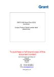
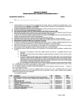
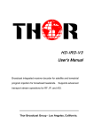
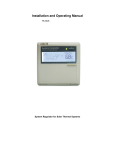
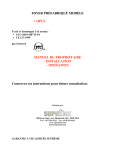
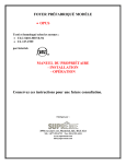
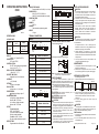
OPERATING INSTRUCTIONS
CH403
36 x 72
SPECIFICATIONS
TERMINAL CONNECTIONS
SETPOINT LIMITS
Resolution
Product
o
o
( C/ F)
CH403
DEFROST FREQUENCY
Programmable from 00 to 99 (hr / min / sec)
POWER SUPPLY
85 to 270 VAC/ DC @ 50/ 60 Hz
24VAC /DC models (Available on request)
OPERATING TEMP
0-50OC
HUMIDITY
95% RH
HOUSING
Flame retardant engineering plastic
WEIGHT
110 gms
CH403-1
Range
-50 to 100oC
-50 to 210oF
0.1
-19.0 to 99.0 oC / oF
DISPLAY
3 digits : 0.4", Bright Red LED's.
SENSOR TYPE
NTC probe TSP04
CONTROL ACTION
ON/ OFF with hysteresis programmable
from 0.1 to 9.9 ( oC / oF )
DISPLAY OFFSET ADJUSTMENT
-19.9 to 20.0 ( oC / oF )
RESTART TIME DELAY
Adjustable from 00 to 99 minutes.
ACCURACY
±1% (full scale)
SETTINGS
Via keys on front panel
RELAY ACTION
a) Heat mode b) Cool mode
SENSOR BREAK
indicated on display, relay off
ALARM INDICATIONS
a) High Alarm: display alternates
between ‘HA’ / ‘PV’ value
b) Low Alarm: display alternates
between ‘LA’ / ‘PV’ value
OUTPUT
For main set point:
SPST, 10A @230 VAC.
SSR drive available on request.
20A relay models available.
For Alarm: 12VDC @ 10mA.
5A relay models available on request.
DEFROST TIME
Programmable from 00 to 99 min
NO COM NC NO2 COM2
!
SENSOR
N
L
1 2 3 4 5 6 7 8 9 10 11 12
+
+ FOR
SSR
TERMINAL DESCRIPTION
Sensor input
NO of relay / +ve of SSR
COM of relay / - ve of SSR
NC of relay
+ve of alarm output / NO2
- ve of alarm output / COM2
N (Neutral)
L (Live)
TERMINAL
7&8
1
2
3
4
5
10
12
TYPICAL CONNECTIONS FOR LOADS
NO COM NC ALARM
+
1
INSTALLATION GUIDELINES
CH403-3
SENSOR
-
N
L
1) For load current less than 0.5A
N
L
TC
1 2 3 4 5 6 7 8 9 10 11 12
+
+ -
TC
C
FOR
SSR
LOAD
NO
R
C
Snubber
TERMINAL
TERMINAL DESCRIPTION
7&8
Sensor input
OR
2) For bigger loads use interposing relay/contactor
N
L
TC
1
NO of relay / +ve of SSR
2
COM of relay / - ve of SSR
3
NC of relay
4
+ve of alarm output
TC
C
Contactor
5
- ve of alarm output
N (Neutral)
R
C
Snubber
LOAD
NOTE: Use snubber as shown above to increase life
of internal relay of temperature controller.
SAFETY SUMMARY
All safety related codifications, symbols and
instructions that appear in this operating manual or on the
equipment must be strictly followed to ensure the safety of
the operating personnel as well as the instrument.
If the equipment is not handled in a manner specified
by the manufacturer it might impair the protection provided
by the equipment.
L (Live)
12
CH403-2
SENSOR
N
L
1 2 3 4 5 6 7 8 9 10 11 12
+
COM
NO
!
CAUTION: Read complete instructions prior to
installation and operation of the unit.
CAUTION: Risk of electric shock.
WIRING GUIDELINES
CAUTION:
TERMINAL
TERMINAL DESCRIPTION
4
NO of relay
2
COM of relay
7&8
Sensor input
10
N (Neutral)
12
L (Live)
!
CAUTION:
1. The equipment shall not be installed in environmental
conditions other than those mentioned in this manual.
2. Fuse Protection:
The equipment does not have a built-in-type fuse.
Installation of external fuse of rating 275VAC/1Amp for
electrical circuitry is highly recommended.
3. Thermal dissipation of equipment is met through
ventilation holes provided on chassis of equipment. Such
ventilation holes shall not be obstructed else it can lead to
a safety hazard.
4. The output terminals shall be strictly loaded to the
manufacturer specified values/range.
MAINTENANCE
NO
C
10
CAUTION:
1. This equipment, being built-in-type, normally becomes
a part of main control panel and in such case
the terminals do not remain accessible to the end user
after installation and internal wiring.
2. Conductors must not come in contact with the internal
circuitry of the equipment or else it may lead to a safety
hazard that may in turn endanger life or cause electrical
shock to the operator.
3. Circuit breaker or mains switch must be installed
between power source and supply terminals to
facilitate power 'ON' or 'OFF' function. However this
switch or breaker must be installed in a convenient
position normally accessible to the operator
1. To prevent the risk of electric shock power supply to the
equipment must be kept OFF while doing the wiring
arrangement. Use lugged terminals to meet M3 screws.
2. Wiring shall be done strictly according to the terminal
layout with shortest connections. Confirm that all
connections are correct.
3. To eliminate electromagnetic interference use of short
wire with adequate ratings and twists of the same in
equal size shall be made.
4. Cable used for connection to power source, must have
a cross section of 1mm2 or greater. These wires shall
have insulation capacity made of at least 1.5KV.
1. The equipment should be cleaned regularly to avoid
blockage of ventilating parts.
2. Please clean the equipment with a clean soft cloth.
Do not use Isopropyl alcohol or any other cleaning agent.
MECHANICAL INSTALLATION
For installing the controller
1. Prepare the panel cutout with proper dimensions as
Panel Cutout
shown (in mm)
33
28 29
75
74.5
71
3.5
2. Push the controller into the panel cutout. Secure the
controller in its place by pushing the clamp on the rear
side.The screws of the clamp, must be in the farthest
forward slot.
3. For proper sealing, tighten the screws evenly with
required torque.
!
CAUTION:
The equipment in its installed state must not come in
close proximity to any heating sources, caustic vapors, oils,
steam, or other unwanted process by-products.
EMC Guidelines:
1. Use proper input power cables with shortest connections
and twisted type.
2. Layout of connecting cables shall be away from any
internal EMI source.
Operating/1005/CH403/OP161-V03B
Page 1 of 2.
CONFIGURATION SCHEME (parameter setting)
To enter configuration: Press
Key press
&
Key press
Display
1. To Lock setpoint
12. To select Audible Alarm
Press
SETPOINT
Unlock
Press
+ /
Lock
2. To select Resolution
Factory setting: 1
for 1 second)
+
/
to change value
7. To select Display Offset
(Display
-19.9 to 20.0
+
/
to change value
8. To select Restart time
delay
RESOLUTION
(Display
Press
+ /
(Display
MODE
Cool mode
Press
+ /
Heat mode
4. To select High Alarm
Factory setting: 100OC
+
/
(Display
for 1 second)
HIGH
ALARM
SP to 100OC
SP to 99OC
(for 0.1resolution)
/
to change value
5. To select Low Alarm
(Display
DEFROST
TIME
Press
O
-50OC to SP
-19 C to SP
LOW
ALARM
(for 0.1resolution)
+
/
to change value
Factory setting: 00min
00 to 99 min
+
/
10. To select Defrost
Frequency
to change value
Factory setting: C
/
Press
00 to 99 units
+
/
11. To select Defrost
Frequency unit
DEFROST
FREQUENCY UNIT
Temp.
Hysteresis
UNIT
Press
+ /
Heater
mode
Celsius
Fahrenheit
14. To select Sensor Break
(Display
for 1 second)
Sensor
Break
Relay OFF
Press
+ /
10 min OFF,
4 min ON
(Off first)
15. Press
to select Reset all
At display = 5, reset all to Factory setting value
Note: Reset all function to be used prior to changing
input (to realign related parameters)
(Display
Cooler
(Relay)
OFF
for 1 second)
RESET ALL
No reset
Press
+
No reset
Press
+
No reset
Press
+
No reset
ON
Cooler
ON
Factory setting: 0
to change value
Time
2. Display Offset adjustment: This function is used to
adjust the display value in cases where it is necessary for
display value to agree with another recorder or indicator, or
when the sensor cannot be mounted in correct location.
3. Defrost mode: The unit has two modes of defrost Auto and Manual. The Auto mode can be set by
programming required defrost frequency between 0 and 99
(Hr / Min / Sec). The defrost frequency excludes the defrost
time. To enable Manual defrost press key continuously for
4 sec. Defrost is valid only for cool mode. During defrost
relay remains OFF for a period = Programmed defrost time.
Defrost once enabled can be disabled only at power ON.
Defrost is disabled if Defrost frequency = 0 or Defrost time =
0.
4. Restart time delay: This parameter is used to protect
the compressor from restarting in a short period of time and
can be set between 0 to 99 minutes.
Example: If this parameter is set at 2 mins, the relay will cut
off at the set temperature, but will not restart for a minimum of
2 mins, even if the differential is achieved earlier.
Factory setting: Hours
NOTE : This parameter will be prompted only if
Defrost time (DFT) > 0
(Display
1) ON/OFF control action (for cooler) : The relay is ‘OFF'
up to a temperature equivalent to SETPOINT + HYST and
‘ON' above this temperature. As the temperature of the
system drops, the relay is switched ‘OFF' at SETPOINT.
Hysteresis: The difference between the temperature at
which relay switches ‘ON’ and at which relay switches ‘OFF’
is the hysteresis or dead band.
set point
Factory setting: 1
for 1 second)
DEFROST
FREQUENCY
Press
+ /
Press
+ /
O
13. To select Units
NOTE : This parameter will be prompted only if
Defrost time (DFT) > 0
Factory setting: -50 OC
for 1 second)
Enable
for 1 second)
(Display
(Display
Press
+ /
to change value
9. To select Defrost time
for 1 second)
Mute
00 to 99 min
Press
Factory setting: Cool
Factory setting: 00
for 1 second)
RESTART
TIME
3. To select Control mode
+
Continuous operation of above makes update speed faster in 3 stages after 7 seconds.
Range: From user programmed Low alarm (LA) to High alarm (HA).
Resolution: 1 / 0.1 programmable.
Default: 0 OC
for 1 second)
Audible
Alarm
Factory setting: 0.0
for 1 second)
DISPLAY
OFFSET
Press
(Display
Factory setting: Mute
Programming Set Point
A) To view set point : Press key
B) To increase / decrease set point : Press
USER GUIDE :
0.1 to 9.9
for 1 second)
+
(Display
Factory setting: 0
(Display
Description
Display
NOTE: Not prompted for 20A relay models
for 1 second)
HYSTERESIS
Press
Factory setting: 0.5
Description
(Display
Press
Key press
for 3 seconds
6. To select Hysteresis
Display
Description
for 1 second)
Hours
Minutes
Seconds
Press
+
Press
+
&
key.
No reset
All reset
After configuration setting:
Press
5. Alarm acknowledgement : To acknowledge the
alarm, press
for 3 secs to exit programming mode
NOTE: No keys pressed in programming mode allows
to quit automatically from programming after 1 min
(Specifications subject to change as development is a
continuous process)
Selec Controls Pvt. Ltd., India
(Formerly Selectron Process Controls Pvt. Ltd.)
Tel:91-22-28476443, Fax:91-22-28471733,
Website: www.selec.com
E- mail: [email protected].
Operating/1005/CH403/OP161-V03B
Page 2 of 2.