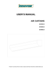
Download AIR CURTAINS INSTALLATION MANUAL
Transcript
AIR CURTAINS
INSTALLATION MANUAL
WRM06+
WRM08+
WRM10+
Thanks for purchasing this Air Curtain,
Please read these instructions carefully before use.
1
1、PRODUCT INTRODUCTION
As one of the new top-class products for modern decoration, air curtain is also matched
with the air-conditioner.And it is installed at the entrances of supermarket,theater,meeting
room,hotel,office room,working shop and storeroom to prevent the dust,mosquito and nocuous
air,and so on.
2、IDENTIFICATION & INSTALLATION DIMENSIONS
F
D
E
WRM06+
A
900
WRM08+
1200
WRM10+
1500
MODEL
B
440
C
D
E
F
90
190
105
260
840
3、INSTALLATION CAUTION
Must follow the following asking when installing air curtain:
3.1Please install the unit in a sturdy place to avoid 3.2 Please install the unit inside the room.
the shaking and ensure its security (because it
maybe causes the wall becoming flexible or shaking
and noise.
3.3 Don’t install the unit too low, no less than 2.3
3.4 Don’t install the unit in a place where it is
meter from the ground. When the entrance is wider splashed by water, exposed to excessive
than the unit, it is recommended to install two or
steam, explosive gas or corrosive gas.
more units in parallel. In this case, provide
20-40mm gaps between the units.
2
φ 40- 50mm
4、INSTALLATION
A、Installing on the concrete wall:
4.1.1 Removed the mounting plate
4.1.2 Fix the bolts in the proper position
Remove the plastic parts, unclamping the fixed (Decide the position with the mounting plate
screws on the back of main body to remove the
and pour cement into the bolt holes.)
mounting plate.
C O N C RE T E
MOUNTING PLATE
PLASTIC PARTS
2
1
1
2
13 -15 m m
7 0 mm
4.1.3 When the cement has freeze, fit the mounting 4.1.4 Install the main body
plate (use the washer and nut according to the
Set the main body onto the upper end of
following)
the mounting plate and clamp it as shown.
1
2
B、Installing on the wooden wall
4.2.1 Fix the mounting plate in the proper
positions with tapping screw.
4.2.2 Same as the step 4 of A
1
MOODEN SC REW
2
M OUN TI NG PI ATE
3
C、Hanging from the ceiling
4.3.1 Remove the mounting plate from main body
(Same as step 5.1.1)
4.3.2 Fixing ceiling brackets as Fig.
C
MOUNTING PIATE
D
C
W A SH E R
S PR IN G WA S HE R
NU T
FIXING SCREW
4.3.3 Set the mounting plate on the ceiling
brackets and ensure safe & fixing (use the bolts
attached to the ceiling brackets as Fig. Using the
ceiling brackets to hang from the ceiling, the
position of mounting plate can be adjusted in the
limit of 100mm.
4.3.4 Do the same as step A to install the
main body.
1
2
D、For above ceiling
4.4.1Fix the air curtain as in the procedure for
installing on the concrete wall.
4.4.2 Then pipe as right Fig. Instructs.
5、HEATED MODEL TECHNICAL PARAMETER
MODEL
Diam
Of
Wheel
(mm)
Volt.
/Freq.
(V~
/Hz)
WRM06+
WRM08+
WRM10+
115
400/50
Ⅰ
Heater
power
(KW)
Ⅱ
Ⅲ
160
2
4
6
200
2.7
5.3
8
230
3.3
6.7
10
Motor
power
(W)
Temp.
(K)
4
Max.air
speed(m/s)
H
35-45
9.5
L
8.5
Air volume
(m3/h)
Noise(db)
H
L
H
L
1200
1000
57
55
13.5
1700
1500
58
56
16
2200
1900
59
57
18.5
Net
weight
(Kg)
LINE SIZE
POWER
ITEM
HEATER POWER(kW)
THREE PHASES
(380V~ MAIN LINE:A、B、C、N)
3
4
5
6
8
10
12
14
MAIN LINE(mm2)
1.5
2.5
4.0
6.0
EARTH LINE(mm2)
0.75
1.5
2.5
4.0
Do not operate the air curtain if there is a voltage overload.
BLUE(BROWN/RED)
THERMAL CUT-OUT
RECEIVER
I/O
com 3 on
com 2 on
com 1 on
BROWN
BLUE
HEATER
THERMAL CUT-OUT
HEATER
GREY
WHITE
YELLOW-GREEN
N A B C PN
5
(YELLOW)
ORANGE
MOTOR
WHITE
THERMAL CUT-OUT
YELLOW-GREEN
BLACK
RECEIVER
IC
c
YELLOW
6. OPERATION
6.1 Control by remote control
a. Press the [ON/OFF] button to turn on the unit. The unit will automatically start in non-heating
mode at high speed. A green light will be displayed on the receiver.
b. Press the [SPEED] button to change the speed of the unit to high or low.
c. FOR THREE PHASE UNIT: Press the [POWER] button to operate the unit in heating mode at
low power. A red light will be displayed on the receiver. Press the [POWER] button again and
the unit will change from low power to medium power with two red lights displayed. Again
press the [POWER] button and the unit will change from medium power to high power with
three red lights displayed. Press the [POWER] button again and the unit will switch from
heating mode to non-heating mode. The red lights displayed change to a single green light.
d. When the unit operates in non-heating mode, press the [ON/OFF] button to turn off the unit.
e. When the unit operates in heating mode, press the [ON/OFF] button. The unit switches to
non-heating mode at high speed. The indication light turns to a green flicker light. The unit will
continue to operate in non-heating mode for 3 minutes and then stop.
6.2 Control by the control panel in the unit is the same function as 6.1.
6.3 Overheat protection:
When the heater temperature overheats (over 135°C), heating mode will stop and switch to
non-heating mode automatically, at the same time the indication light will change to green. Once
the heater temperature drops down below 135°C, press the [POWER] button to continue working
in heating mode.
7. CAUTIONS
a) Use the unit at the rated voltage and frequency indicated on the nameplate.
b) Please do not connect power supply until the machine is installed.
c) Maintenance must be done every year.
d) Never use petrol, benzene, thinner or any other such chemical for clearing the unit.
e) Don’t allow water or any substances enter the motor.
f) When connected with power socket, it is advisable to choose an appropriate plug. If connected to
a power source directly, use a safety switch.
6


