1
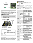
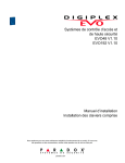
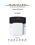
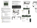
Connecting the External Negative Trigger
Access Control Module V4.1
Figure 2: Additional Connection Information
Figure 5: Connecting Access Control Devices
The DGP-ACM12 comes with an external negative trigger. You can use a
PGM from the control panel or another module to release the access
control door lock. The external negative trigger can also be triggered
using a push-button. When the push button is pressed, the door will
unlock. The PGM or push-button must ground the negative trigger.
Connect the push-button as shown in Figure 2.
No EOL required
on REX
LED Display
AC (Green): On when receiving AC power.
BATT (Green): On when charging and during battery tests.
AUX (Yellow): On when auxiliary output is active.
ERROR (Red):Indicates a problem with the module.
RX (Green): Flashes when receiving information from the panel.
TX (Green): Flashes when transmitting information to the panel.
To PGM output
DGP-ACM12
Installation Instructions
paradox.com
Printed in Canada 09/2007
Introduction
External Negative Trigger
Error
RX
TX
Condition
ON
OFF
OFF
ON
OFF
ON
ON
ON
OFF
ON
ON
ON
Flash
----
----
Combus is shorted / No clock / No data
Wrong data / Invalid Combus address
(Too many modules)
Future Use
Combus lines reversed (YEL and
GRN)
Combus power is too low
ACM12-EI01
Disconnect the battery before
replacing the fuse.
*** = If the Request for Exit (REX) device is not used,
place a jumper across the AUX- and REX terminals.
Figure 6: Connecting for Firmware Upgrade (CONV4USB)
Figure 3: Connecting a 4-Wire Reader (DGP-R910 / DGP-R915)
If the DGP-ACM12 loses
communication with the
reader, it will show up as a
Module Fail to Com.
trouble.
Allows access with Card and Pin and Card or PIN when used with a
DGP-R915 or CR-R885-BL
Allows arming with PIN or Card and PIN when used with a DGP-R915
Transformer Sharing: Use one transformer to power multiple modules
with transformer sharing. Respect the maximum power output of the
transformer. See Figure 1 for more information.
Connected up to 300m
(1000ft) away.
1:
2:
3:
4:
Technical Specifications
AC Power:
16Vac, 20/40VA, 50 - 60Hz
Aux. Power:
12Vdc, typical 600mA, 1A max.
Battery:
12Vdc, 4Ah minimum
No. of Outputs:
2; one 50mA PGM output, one form C relay rated at 5A/
28Vdc, N.O./N.C.
No. of Zones:
2 (Door Contact & REX device)
No. of Inputs:
2 (Negative Trigger & Tamper inputs)
Any DGP-848 control panel with access control
Any DGP-NE96 control panel
Any EVO control panel
12Vdc
Combus
Reader
RED
BLK
GRN
YEL
to
to
to
to
ACM-12
(+)
(-)
(D0)
(D1)
Only connect one reader per
DGP-ACM12
Digiplex/
Digiplex EVO
series control
panel
Rechargeable Battery:
12V 4Ah min
DGP-R915
DGP-R910 (not shown) is connected the same way
AWG #14 single
conductor solid
copper wire
Figure 4: Connecting a 7-Wire Routing Cable
To metallic enclosure
Cold water pipe
grounding
Installation
Ground clamp
The module is connected to the control panel’s combus as shown in Figure 1.
Please refer to the control panel’s Programming Guide for the maximum
installation distance. Devices connected to the PGM output must be
connected as shown in Figure 2. Refer to Figure 5 for connection drawings for
the REX device, reader, locking device and door contact.
The door contact follows the control panel’s EOL definition. When
EOL is enabled and the door contact is not used, place a 1k9 resistor
across the CT and AUX- input terminals. If EOL is disabled, use a
jumper. If the REX device is not used, place a jumper across the REX
and AUX- terminals.
CONV4USB
AUX switch:
Press to toggle the AUX output.
The backlight intensity defaults in sections [025] and [026] are now 003
Control Panel
Compatibility:
1N4007
Diode
Anode
** = If the door contact is not used, install a jumper or a
1k9 resistor across the AUX- and CT terminals
depending on the control panel’s EOL definition.
Figure 1: Connecting the power and combus
What’s New 4.0
•
•
Cathode
Transformer Sharing
Transformer Sharing: Use one transformer to power
multiple modules with transformer sharing.
From
transformer
Connect to another
module compatible with
transformer sharing
If you use a routing cable, use a
shielded routing cable. Do not
connect the routing cable’s shield to
the reader’s shield. Only connect the
routing cable’s shield at the DGPACM12.
Connected up to 152m
(500ft) away.
AC Power
Use a 16.5Vac (50/60 Hz) transformer with a minimum 20VA. as shown
in Figure 1. Do not use any switch-controlled outlets to power the
transformer.
Backup Battery
To power the module’s door lock relay during a power failure, connect a
12Vdc 4Ah rechargeable acid/lead or gell cell backup battery as shown in
Figure 1. Connect the battery after applying AC power.
Inverting the polarity when installing the battery will blow the battery
fuse.
** Door contact
must be
connected to CT
terminal
* = Follows control panel’s EOL definition.
Connection Diagrams
What’s New 4.1
•
When connecting the diode to the door lock, be
sure to connect the cathode of the diode to the
positive (+) voltage and the anode to the negative
(-) voltage.
PGM
DGP-ACM12
The Access Control Module (DGP-ACM12) is designed to be used with the
Digiplex EVO System control panels. Each DGP-ACM12 allows you to
connect a reader, a REX device, a door contact and a locking device to
control the access to one door. If desired, door contacts can also be assigned
to zones in the control panel to link the doors to the alarm system. This will
allow you to use the same door for the access control system and the alarm
system.
•
External Tamper
Switch (N.C.)
And / Or
Table 1: Special Display
*** REX device must be
connected to REX terminal
Connect
Reader
1: Red
2: Black
3: Green
4: White
5: Brown
6; Orange
7: Yellow
to
to
to
to
to
to
to
ACM-12
(+)
(-)
(D0)
(D1)
(Beep)
(RED)
(GREEN)
Only connect one reader per
DGP-ACM12
CR-R880-BL
CR-R885-BL (not shown) is connected the same way
U = Default setting
SECTION [001]: Partition Assignment
Option
[1]
Partition 1
[2]
Partition 2
[3]
Partition 3
[4]
[5]
[6]
Partition 4
Partition 5
Partition 6
OFF
N Disabled
N Disabled
N Disabled
ON
U Enabled
U Enabled
U Enabled
N Disabled
U Enabled
N Disabled
N Disabled
U Enabled
U Enabled
SECTION [002]: General Options 1
Option
[1]
Tamper Input
[2]
Battery Charging Current
[3]
Reader’s red LED to follow partition’s
status
[4]
Reader’s beeping to follow partition’s
status when option [3] is ON
[5]
Card activates door unlocked schedule
[6]
Door will relock
[7]
Partition 7
N Disabled
U Enabled
[7]
[8]
Partition 8
N Disabled
U Enabled
[8]
SECTION [003]: General Options 2
Option
[1]
Door Left Open Alarm
[2]
[3]
[4]
Door Left Open Pre-alarm
Door Left Open Alarm
Door Left Open Alarm follows
[5]
[6]
[7]
Door Forced Open Alarm
Door Forced Alarm
Door Forced Alarm follows
OFF
ON
U Disabled N Enabled
N Disabled
N Silent
U Alarm
Restore
[8]
[010]
[011]
[012]
[013]
N Silent
U Alarm
Restore
NVisual
Reader Access Feedback
Section
[005]
[006]
[007]
[008]
[009]
U Disabled
U Enabled
U Audible
N Beep
Timer
N Enabled
SECTION [004]: PGM Options
Option
[1]
PGM Deactivation After
N Disabled
U Enabled
N Disabled
U Enabled
diately
N Disabled
U Enabled
N Disabled
U Enabled
U Imme-
N When
closed
ON
N PGM Timer
N Card Only
N PIN Only
N Card and PIN
U Card or PIN
OFF
ON
OFF
ON
OFF
OFF
ON
ON
[6]
Reader Locate Feedback
U Visual
[7]
[8]
Unlock Door on Fire Alarm
AC and Battery Supervision
U Disabled
U Enabled
[2]
PGM Normal State
[3]
PGM Base Time
[4] & [5] Special
N Beep
Timer
SECTION [022]: Safe Mode Options
Option
[1]
Safe Mode
N N.C.
N 1 minute
[5]
N Visual &
audible
N Enabled
N Disabled
[2]
Safe Mode Access
N Disabled
[3]
Reader Safe Mode Feedback
U Visual
[4]
[5]
Unlock Door in Safe Mode
Access Cards in Safe Mode
Section
[023]
[024]
[025]
[026]
[027]
[028]
[029]
[030]
[032]
[040]
ON
U Enabled
U Enabled
N Visual &
audible
U Disabled N Enabled
N Any Cards
U Safe
Cards only
N N/A
N N/A
SECTION [031] PGM Options 2
Option
[1]
Flexible PGM Deactivation Option
Delete All Safe Mode Access Cards
Default
030
__/__/__ (001 to 255 seconds)
Door Unlocked Period
005
__/__/__ (001 to 255 seconds added to section [006])
Door Unlocked Period extension
015
[070]
[071]
[072]
[073]
[074]
__/__/__ (001 to 255 seconds)
__/__/__ (001 to 255 seconds)
Time to start pre-alarm before alarm is triggered
__/__/__ (001 to 255 seconds)
Door Left Open Interval
Door Left Open Pre-Alarm Timer
060
015
Warranty
Beep timer for Door Left Open Alarm
005
__/__/__ (001 to 255 seconds)
Beep timer for Door Forced Open alarm
005
__/__/__ (000 to 255; refer to option [3] in section [004])
PGM timer
005
[2]
Reload Timer on Activation Event
[3] to [8] Future Use
End Time
___ ___ : ___ ___
___ ___ : ___ ___
Event Group
Feature Group
Section
Section
PGM Activation
[014]
__/__/__
[015]
__/__/__
PGM Deactivation
[018]
__/__/__
[019]
__/__/__
Only Event Groups 000 to 055, 062 and 063 can be used to program the module’s PGM.
S M T
1 2 3
1 2 3
W T
4 5
4 5
Start #
Section
[016]
__/__/__
[020]
__/__/__
F S
6 7
6 7
H
8
8
End #
Section
[017]
__/__/__
[021]
__/__/__
Reload
N N/A
Assign Safe Mode Access Card 2 (Present Card 3 Times)
Assign Safe Mode Access Card 3 (Present Card 3 Times)
Assign Safe Mode Access Card 4 (Present Card 3 Times)
Delete Safe Mode Access Card 1
Delete Safe Mode Access Card 2
Delete Safe Mode Access Card 3
Delete Safe Mode Access Card 4
For complete warranty information on this product please refer to the Limited Warranty Statement found on the website www.paradox.com/terms. Your use of the Paradox product signifies your acceptance of all
warranty terms and conditions.
We strongly advise that you review and take into consideration the “Limitations of Alarm Systems” document available on our website at http://paradox.com/Terms/.
© 2003-2007 Paradox Security Systems Ltd. All rights reserved. Specifications may change without prior notice. One or more of the following US patents may apply: 7046142, 6215399, 6111256, 6104319, 5920259,
5886632, 5721542, 5287111, 5119069, 5077549 and RE39406 and other pending patents may apply. Canadian and international patents may also apply.
Digiplex EVO is a trademark or registered trademark of Paradox Security Systems Ltd. or its affiliates in Canada, the United States and/or other countries.
Start Time
___ ___ : ___ ___
___ ___ : ___ ___
U Don’t
ON
N Timer /
Deactivation
event
N Reload
Timer
N N/A
Description
Default
(001 to 024 hours; 000 = Disabled)
Safe Mode Door Unlocked Period
000
(001 to 255 seconds; 000 = Follow REX)
REX Unlocked Period
000
(000 to 003)
Red LED Brightness
003
(000 to 003)
Green LED Brightness
003
(000 to 003)
Buzzer Frequency
001
(000 to 255 minutes; 000 = instant)
AC Restore Report Delay
005
(000 to 255 minutes)
Stay Lock Delay
000
Test PGM: Activates the PGM for 8 seconds to verify if the PGM is functioning properly.
__/__/__ (000 = steady, 001 to 254 = pulsed (increments of 8ms), 255 = pulsed fire)
PGM Output type
000
Access Card Serial Number Display: View an access card’s serial number displayed on any LCD or Grafica keypad on the combus.
When the DGP-ACM12 is in access card display mode, the door connected to the module cannot be accessed.
Assign Safe Mode Access Card 1 (Present Card 3 Times)
Description
AC failure report delay
Door unlock schedule
OFF
U PGM
Data
__/__/__
__/__/__
__/__/__
__/__/__
__/__/__
__/__/__
__/__/__
[061]
[062]
[063]
[064]
Data
__/__/__ (000 to 255 x 1 minute; 000 = Instant)
Schedule A:
Schedule B:
OFF
N Disabled
Timer only
[6] to [8] Future Use
OFF
U Deactivation Event
U N.O.
U 1 second
[4]
U Audible
U Visual &
audible
Reader’s green LED for Access
Granted
Unlock on Request for Exit (REX)
OFF
ON
U Disabled N Enabled
N 850mA
U 350mA
N Disabled U Enabled
Technical Support
For technical support in Canada or the U.S., call 1-800-791-1919, Monday to Friday from 8:00 a.m. to 8:00 p.m. EST.
For technical support outside Canada and the U.S., call 00-1-450-491-7444, Monday to Friday from 8:00 a.m. to 8:00 p.m. EST.
Please feel free to visit our website at www.paradox.com.