1
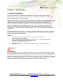
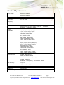
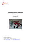
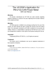
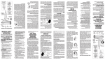
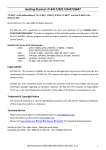
PM-213x User Manual, v1.5 Last Revised: December 2010 Copyright © ICP DAS Co., Ltd. All Rights Reserved. www.icpdas.com Page: 1 E-mail: [email protected] Directory Chapter 1 Introductions 4 1.1 Product Introduction 10 Chapter 4 : Wiring Diagrams 4.1 Connection Diagrams 1.2 Caution 1.2.1 Danger Chapter 5 : 14 Dip switch On/Off 1.2.2 Products Warranty and Customer Support 1.2.3 Limitation of Warranty Chapter 6: Communication Formats 16 6.1 Specification Chapter 2: Specification 6 6.2 Modbus Register Chapter 3 : Installation 7 Chapter 7: CAN Bus 21 3.1 Inspection 7.1 Overview 3.2 safety 7.2 Contact mark 22 3.3 Dimension and Latch 7.3 DIP Switch 23 3.4 Mounting and Dismounting 7.3.1 The Node-ID of CAN bus 3.4.1 Mounting 7.3.2 The baud rate of CAN bus 3.4.2 Dismounting 7.3.3 The LED state 3.5 CT’s installation steps 26 7.4 CAN Protocol 7.4.1 Specification 7.4.2 Polling Mode PM-213x User Manual, v1.5 Last Revised: December 2010 Copyright © ICP DAS Co., Ltd. All Rights Reserved. www.icpdas.com Page: 2 E-mail: [email protected] 7.4.3 Auto Response Mode 7.4.3.1 Set Auto Response Parameters 7.4.3.2 Get Auto Response Parameters 7.4.3.3 Set Meter Parameter mode 7.4.3.4 Read Meter Parameter mode 7.4.4 Read Firmware Version 7.4.5 The Value-ID and Power Meter Data Table 33 7.5 CAN Protocol Examples 7.5.1 Polling Example 7.5.2 Set Auto Response Parameter Example 7.5.3 Get Auto Response Parameter Example 7.5.4 Read Firmware Example Appendix 1 : Question and Answer 38 Appendix 2: :PVC wire and Product model 39 PM-213x User Manual, v1.5 Last Revised: December 2010 Copyright © ICP DAS Co., Ltd. All Rights Reserved. www.icpdas.com Page: 3 E-mail: [email protected] Chapter 1 : Introduction 1.1 Product Introduction It’s always difficult but crucial to the supervisors to figure out how much energy is consuming. ICP DAS brings the most powerful, cost effective, advanced Compact Power Meters, PM213X series, to the markets. With its high accuracy (1%, PF=1), the PM213x series products can be applied both on low voltage primary side and/or medium/high voltage secondary side and enable the users to obtain in real time the reliable and accurate energy consumption readings from the monitored equipments while in operation. These compact size and cost effective Power Meters are equipped with revolutionary wired clip-on CT (various types support input current up to 200A) and standard Modbus communication RS-485 protocol for easy deployment. It works with input voltages ranging 10V ~ 500V, supporting a wide range of applications. ICP DAS offers PM-213X family in a full range of Single-phase and Three-phase compact power meters for power monitoring. The products offer a rich feature set combined with easy-to-integrate communications. Features: : 1. True RMS energy and power parameters measurement in compact size. 2. Easy wiring for on-line installation. 3. RS-485 communication supported Modbus RTU protocol , CAN Bus Communication supported Compatible with CAN specification 2.0B. 4. Wh accuracy better than 1% (PF=1). 5. With wired clip-on CT (various types support input current up to 200A) . 6. LED pulse output. 1.2 Caution 1.2.1 Danger The meter contains hazardous voltages, and should never be disassembled. Failing to follow this practice will result in serious injury or death. Any work on or near energized meters, meter sockets, or other metering equipment could induce a danger of electrical shock. It is strongly recommended that all work should be performed only by qualified industrial electricians and metering specialist. ICP DAS assumes no responsibility if your electrical installer does not follow the appropriate national and local electrical codes. PM-213x User Manual, v1.5 Last Revised: December 2010 Copyright © ICP DAS Co., Ltd. All Rights Reserved. www.icpdas.com Page: 4 E-mail: [email protected] 1.2.2 PRODUCT WARRANTY & CUSTOMER SUPPORT ICP DAS warrants all products free from defects in material and workmanship for a period of one year from the date of shipping. During the warranty period, we will, at our position, either repair or replace any product that proves to be defective. To report any defect, please contact :+886-3- 597-3366 or [email protected]. Please have the model, serial number and a detailed problem description available when you call. If the problem concerns a particular reading, please have all meter readings available. When returning any merchandise to ICP DAS, a return SN. is required. 1.2.3 LIMITATION OF WARRANTY This warranty does not apply to defects resulting from unauthorized modification, misuse, or use for reason other than electrical power monitoring. The supplied meter is not a user-serviceable product. PM-213x User Manual, v1.5 Last Revised: December 2010 Copyright © ICP DAS Co., Ltd. All Rights Reserved. www.icpdas.com Page: 5 E-mail: [email protected] Chapter 2 Specifications Input Voltage PM-2134:10-300V PM-2133:10-500V Input Current CT Φ10mm (60A),CT Φ16mm(100A),CT Φ24mm( 200A) Aux Power DC +10~+30V Frequency 60/50Hz Starting Current <0.025A Wiring diagram PM-2134:1-phase 4-channel PM-2133:Auto or manual setting 1P2W-1CT、1P3W-2CT、 3P3W-2CT、3P3W-3CT、3P4W PM-2134: : V1(rms), V1(rms), V2(rms), V2(rms) I 1(rms), I 2(rms), I 3(rms), I 4(rms) kW1, kW2, kW3, kW4 kVA1, kVA2, kVA3, kVA4 kvar1, kvar2, kvar3, kvar4 PF1, PF2, PF3, PF4 kWh1, kWh2, kWh3, kWh4 kVAh1, kVAh2, kVAh3, kVAh4 kvarh1, kvarh2, kvarh3, kvarh4 Power Parameters Measures Communication PM-2133: : VA(rms), VB(rms), VC(rms), Vave(rms) I A(rms), I B(rms),I C(rms), I ave(rms) kWA, kWB, kWC, kWtot kVAA, kVAB, kVAC, kVAtot kvarA, kvarB, kvarC, kvartot PFA, PFB, PFC, PFtot kWhA , kWhB, kWhC, kWhtot kVAhA , kVAhB, kVAhC, kVAhtot kvarhA , kvarhB, kvarhC, kvarhtot Protocol:Modbus-RTU RS485, half duplex isolated Baud Rate:9600, 19200(default), 38400 Protocol:CAN bus Baud Rate:125 k(default),250 k,500 k,1000 k kWh Accuracy 1% (PF=1) Dimension 78(L) × 35(W) × 99(H) mm Operating Temperature -10℃~70 ℃ Installation Rail-mounted Power consumption 2.4W(When RS485 communication) PM-213x User Manual, v1.5 Last Revised: December 2010 Copyright © ICP DAS Co., Ltd. All Rights Reserved. www.icpdas.com Page: 6 E-mail: [email protected] Chapter3: Installation 3.1 Inspection The instrument is no longer safe when, a) shows clear signs of damage b) does not work c) long storage under extreme conditions d) damage during shipment 3.2 Safety Please use the soft dry clothes to clean the instrument. Please do not use any chemical or detergent or volatile solvents to clean the instrument, in order to avoid any possibility of the cover damage。 3.3 Dimension and Latch Top View (mm) Side View (mm) PM-213x User Manual, v1.5 Last Revised: December 2010 Copyright © ICP DAS Co., Ltd. All Rights Reserved. www.icpdas.com Page: 7 E-mail: [email protected] Position of latch Dimension: 99mm(length)× 32mm(wide)× 78mm(high) Products come with external split type clip-on CT’s. Disconnect the CT’s or use other CT’s is highly prohibited. Please read this operation manual carefully before using。 Please re-confirm the measure position。 Reconfirm the RST(ABC) phase sequence of the power sys PM-213x series can be installed as rail mounting mode or embedded, no need to drill a hole or screw to fix it(rail mounting width can up to the length of 35 mm )。 Meter auxiliary power for PM-213x series is DC +10V ~+30V。 3.4 Mounting and Dismounting 3.4.1 Mounting Pull down the “latch” of meter, and mount the meter on to the rail and lock it, as shown in below picture. Pull down 3.4.2 Dismounting Wire Disconnection 1. the CT’s first and remove CT’s from the monitoring power cables,Do not disconnect CT’s lines from terminals of these smart meters. 2. Disconnect the voltage input wires from terminals and wrap the wire tips with plastic tape. 3. Disconnect the communication wires from terminal. 4. Disconnect the auxiliary power from terminal and wrap the wire tip with plastic tape. Dismount From the back to pull down the latch, then can release the meter PM-213x User Manual, v1.5 Last Revised: December 2010 Copyright © ICP DAS Co., Ltd. All Rights Reserved. www.icpdas.com Page: 8 E-mail: [email protected] 3.5 CT’s installation steps 1 At the bottom of the CT, there is a “K→L” mark. ○ 3 Make sure the power current direction follow ○ the “K→L” mark on the CT and then 2 open the clip-on type CT。 ○ 4 Installation steps finished. ○ clip it on. PM-213x User Manual, v1.5 Last Revised: December 2010 Copyright © ICP DAS Co., Ltd. All Rights Reserved. www.icpdas.com Page: 9 E-mail: [email protected] Chapter 4 : Wiring Diagrams Voltage Input PM-2134 series: Input Voltage up to 300V, PM-2133 series: Input Voltage up to 500V. For any higher Input Voltage large than 500V, please add the PT(power transformer), and Change PT RATIO setup. Confirm the RST (ABC) phase sequence. Current Input The external CT’s are fragile, please handle with care. The current input of PM213x series is in mA range. Only the ex-factory attached CT’s can be used. The other CT’s, for example, from panel will damage the instrument due to its large current (around 5A) When more than one smart meters (PM-213x series) are installed, please do not disconnect the CT with its original meter and mix use with each other. Since each set of smart meter (PM213x series) and its attached split type clip-on CT are calibrated set by set. The mix use may cause wrong measurements. To install CT’s correctly, please ensure the CT lines sequences is right before clip the CT’s onto the power cable of the monitoring equipment. (Detail will be found in next section) In any circumstance, please make sure the CT had been disconnected with the power cable of monitoring equipments, before the CT lines detach from the terminals of the smart meter. Otherwise, the fetal damages may happen. Please handle with extra care, especially when the operation space of CT’s is limited. The current direction must follow K-L marked on CT’s. Please select the right size CT’s for different size of monitoring equipment cables: power cable diameter <Φ10 use 60A CT,Φ10~Φ16 use 100A CT,Φ16~Φ24 use 200A CT。 The maximum current value can not exceed the CT rating. For the consideration of accuracy, 3CT solution is highly recommended for the use in 3P3W compared with 2CT solution. PM-213x User Manual, v1.5 Last Revised: December 2010 Copyright © ICP DAS Co., Ltd. All Rights Reserved. www.icpdas.com Page: 10 E-mail: [email protected] 4.1 Connection diagram PM-2134 Please firstly check the current input terminal, and then in the white black, white black, white black, white black wired sequences(1S 1L 2S 2L 3S 3L 4S 4L).After connect the CT’s, clip on CT’s. Make sure the arrow direction sign on CT’s follows current flow direction(K→L)Note: it must be in the same direction。 Connect the voltage input terminal. For PM-2134, connect V2- V2+ and V1- V1+。 PM-2133 Please firstly check the current input terminal, and then in white black, white black, white black wire sequences(1S 1L 2S 2L 3S 3L. After connect the CT’s, clip on CT’s. Make sure the arrow direction sign on CT’s follows current flow direction(K→L)Note: it must be in then same direction。 Connect the voltage input terminal N C B A. for PM-2133, in the three phase order as follows on N C B A。 Attention please!! For 3P3W ,connect in C A N phase sequence ,do not connect phase B (Check the diagram)。 。 Then, Connect RS485 D+ D- (”-”, ”+” sequence base on the top cover mark showed)。 And then, add the auxiliary power。DC+10~+30V (+ - FG) PM-213x User Manual, v1.5 Last Revised: December 2010 Copyright © ICP DAS Co., Ltd. All Rights Reserved. www.icpdas.com Page: 11 E-mail: [email protected] 1S 1P4W(PM-2134) 1L 2S 2L 3L 3S 4S 4L V2+ V2- V1- L1 L1 L1 L2 L2 L2 L1 L1 L1 L2 L2 L2 1P2W-1CT(PM-2133) 1S 1L 2S 2L 3S 3L N C B A 2S 2L 3S 3L N C B A A B C 1P3W-2CT(PM-2133) 1S 1L A B C 3P3W-2CT(PM-2133) 1S 1L 2S 2L 3S N 3L C B A A B C PM-213x User Manual, v1.5 Last Revised: December 2010 Copyright © ICP DAS Co., Ltd. All Rights Reserved. www.icpdas.com Page: 12 E-mail: [email protected] V1+ 3P3W-3CT(PM-2133) 1S 1L 2S 2L 3S N 3L C B A A B C attention! ! if 3P3W/2CT & 3P3W/3CT, connect only ”A N C” terminal , replace B with N。 。 N C B A or N C B for the voltage input A Correct S N T C R B T S R A Wrong T S R 3P4W-3CT(PM-2133) 1S 1L 2S 2L 3S N 3L C B A A B C N PM-213x User Manual, v1.5 Last Revised: December 2010 Copyright © ICP DAS Co., Ltd. All Rights Reserved. www.icpdas.com Page: 13 E-mail: [email protected] Chapter 5 : Dip Switch ON /OFF: Modbus Address Setting, Wh pulse output and Wiring Setting. Dip Switch Dip switch is used for Modbus address setting, default is 1, i.e. all OFF For example: Modbus address is 10,find the table of dip switch 1-6 is on, off, off, on, off, off ff SW1 -6 setting the Modbus address of communication, 1-64 Modbus Address 1 2 3 4 5 6 7 8 9 10 11 12 13 14 15 16 17 18 19 20 21 22 23 24 25 26 27 28 29 1 2 3 4 5 6 OFF ON OFF ON OFF ON OFF ON OFF ON OFF ON OFF ON OFF ON OFF ON OFF ON OFF ON OFF ON OFF ON OFF ON OFF OFF OFF ON ON OFF OFF ON ON OFF OFF ON ON OFF OFF ON ON OFF OFF ON ON OFF OFF ON ON OFF OFF ON ON OFF OFF OFF OFF OFF ON ON ON ON OFF OFF OFF OFF ON ON ON ON OFF OFF OFF OFF ON ON ON ON OFF OFF OFF OFF ON OFF OFF OFF OFF OFF OFF OFF OFF ON ON ON ON ON ON ON ON OFF OFF OFF OFF OFF OFF OFF OFF ON ON ON ON ON OFF OFF OFF OFF OFF OFF OFF OFF OFF OFF OFF OFF OFF OFF OFF OFF ON ON ON ON ON ON ON ON ON ON ON ON ON OFF OFF OFF OFF OFF OFF OFF OFF OFF OFF OFF OFF OFF OFF OFF OFF OFF OFF OFF OFF OFF OFF OFF OFF OFF OFF OFF OFF OFF PM-213x User Manual, v1.5 Last Revised: December 2010 Copyright © ICP DAS Co., Ltd. All Rights Reserved. www.icpdas.com Page: 14 E-mail: [email protected] 30 31 32 33 34 35 36 37 38 39 40 41 42 43 44 45 46 47 48 49 50 51 52 53 54 55 56 57 58 59 60 61 62 63 64 ON OFF ON OFF ON OFF ON OFF ON OFF ON OFF ON OFF ON OFF ON OFF ON OFF ON OFF ON OFF ON OFF ON OFF ON OFF ON OFF ON OFF ON PM-213x User Manual, v1.5 OFF ON ON OFF OFF ON ON OFF OFF ON ON OFF OFF ON ON OFF OFF ON ON OFF OFF ON ON OFF OFF ON ON OFF OFF ON ON OFF OFF ON ON ON ON ON OFF OFF OFF OFF ON ON ON ON OFF OFF OFF OFF ON ON ON ON OFF OFF OFF OFF ON ON ON ON OFF OFF OFF OFF ON ON ON ON ON ON ON OFF OFF OFF OFF OFF OFF OFF OFF ON ON ON ON ON ON ON ON OFF OFF OFF OFF OFF OFF OFF OFF ON ON ON ON ON ON ON ON ON ON ON OFF OFF OFF OFF OFF OFF OFF OFF OFF OFF OFF OFF OFF OFF OFF OFF ON ON ON ON ON ON ON ON ON ON ON ON ON ON ON ON Last Revised: December 2010 Copyright © ICP DAS Co., Ltd. All Rights Reserved. www.icpdas.com OFF OFF OFF ON ON ON ON ON ON ON ON ON ON ON ON ON ON ON ON ON ON ON ON ON ON ON ON ON ON ON ON ON ON ON ON Page: 15 E-mail: [email protected] SW7-8 : For Single-phase Meter(PM-2134 series): are used to select Wh pulse output. For Three-Phase Meter(PM-2133 series):are used to select the way of wiring. PM-2134: :Select Wh pulse output Wh pulse output Wh1 7 OFF 8 OFF Wh2 ON OFF Wh3 OFF ON Wh4 ON ON PM-2133: :Select the different wiring mode (please select the AUTO, if 1P2W or 1P3W are used) 接線方式 Automatic 7 OFF 8 OFF 3P3W and 2CT 3P3W and 3CT ON OFF OFF ON 3P 4W ON ON Chapter 6 communication Formats 6.1 Specifications Communication protocol :Modbus Transport specification Bits per Byte:1 start bit 8 data bits, least significant bit sent first 1 or 2 stop bits(default = 1, stop) Error Check:Cyclical Redundancy Check(CRC) Baud Rate:9600, 19200(default), 38400 Modbus slave address:1-64(default:1) Modbus Function Code:03h, 04h, 10h Code 03h 04h 10h MODBUS_ name Read Holding Registers Read Input Registers Pre-set Multiple Registers Description Read the contents of read/write location Read the contents of read only location Set the contents of read/write location Note: the max. data reading of Function 03 and Function04 PM-213x User Manual, v1.5 Last Revised: December 2010 Copyright © ICP DAS Co., Ltd. All Rights Reserved. www.icpdas.com is 125 registers Page: 16 E-mail: [email protected] Format of data Integer: 16 bits with sign Unsigned Integer:16 bits without sign Float:IEEE 754 Format ,each with 2 registers, Low Word is first priority while transmit IEEE 754 Format Definition of the floating format of the Bits Data Hi Word, Data Hi Word, Data Lo Word, Data Lo Word, Hi Byte Lo Byte Hi Byte Lo Byte SEEE EEEE EMMM MMMM MMMM MMMM MMMM MMMM S E - 127 Value = (-1) 2 (1.M) 0 < E < 255 Where: S represents the sign bit where 1 is negative and 0 is positive E is the two’s complement exponent with an offset of 127. i.e. an exponent of zero is represented by 127, an exponent of 1 by 128 etc. M is the 23-bit normal mantissa. The highest bit is always 1 and, therefore, is not stored. transport sequence(Float) 1 Data Lo Word,Hi Byte 2 Data Lo Word, Lo Byte 3 Data Hi Word, Hi Byte transport sequence(Integer) 1 2 Data Hi Word,Hi Byte PM-213x User Manual, v1.5 3 Data Hi Word, Lo Byte 4 Data Lo Word, Hi Byte Last Revised: December 2010 Copyright © ICP DAS Co., Ltd. All Rights Reserved. www.icpdas.com 4 Data Hi Word,Lo Byte Data Lo Word,Lo Byte Page: 17 E-mail: [email protected] 6.2 Modbus Register Modbus Module #1 Holding Register : Setup Parameter Modbus Register Parameter name Modicom Format Data Type Len Range Default value Units 1 bps Comment Hex 0: 9600 Comm_485_BaudRate 44097 0x1000 Word UInt 1: 19200 2: 38400 0:1 Stop bit, Comm_485_StopBit 44098 0x1001 Word UInt 0 1:2 Stop bit Meter_Ratio 44099 0x1002 Word UInt 1-65535 500 PT_Ratio 44100 0x1003 Word UInt 1-65535 10 CT_Ratio 44101 0x1004 Word UInt 1-65535 1 0.1 Modbus Module #2 Input Register : Voltage, Current, Power, Energy(Float) for PM-2133、 、PM-2134 Parameter name V_a I_a kW_a kvar_a kVA_a PF_a kWh_a kvarh_a kVAh_a V_b I_b kW_b kvar_b Modbus Register Modicom Format 3435334354 3435534356 3435734358 3435934360 3436134362 3436334364 3436534366 3436734368 3436934370 3437134372 3437334374 3437534376 3437734378 PM-213x User Manual, v1.5 Len Data Type DWord Units Comment Float Volt Primary DWord Float Amp Primary DWord Float kW Primary DWord Float kvar Primary DWord Float kVA Primary DWord Float Primary DWord Float Primary DWord Float Primary DWord Float Primary DWord Float Volt Primary DWord Float Amp Primary DWord Float kW Primary DWord Float kvar Hex 0x11000x1101 0x11020x1103 0x11040x1105 0x11060x1107 0x11080x1109 0x110A0x110B 0x110C0x110D 0x110E0x110F 0x11100x1111 0x11120x1113 0x11140x1115 0x11160x1117 0x11180x1119 Range Last Revised: December 2010 Copyright © ICP DAS Co., Ltd. All Rights Reserved. www.icpdas.com Page: 18 E-mail: [email protected] kVA_b PF_b kWh_b kvarh_b kVAh_b V_c I_c kW_c kvar_c kVA_c PF_c kWh_c kvarh_c kVAh_c V_avg(V_d) I_avg(I_d) kW_tot(kW_d) kvar_tot(kvar_d) kVA_tot(kVA_d) PF_avg(PF_d) kWh_tot(kWh_d) kvarh_tot(kvarh_d) kVAh_tot(kVAh_d) 3437934380 3438134382 3438334384 3438534386 3438734388 3438934390 3439134392 3439334394 3439534396 3439734398 3439934400 3440134402 3440334404 3440534406 3440734408 3440934410 3441134412 3441334414 3441534416 3441734418 3441934420 3442134422 3442334424 0x111A0x111B 0x111C0x111D 0x111E0x111F 0x11200x1121 0x11220x1123 0x11240x1125 0x11260x1127 0x11280x1129 0x112A0x112B 0x112C0x112D 0x112E0x112F 0x11300x1131 0x11320x1133 0x11340x1135 0x11360x1137 0x11380x1139 0x113A0x113B 0x113C0x113D 0x113E0x113F 0x11400x1141 0x11420x1143 0x11440x1145 0x11460x1147 Primary kVA DWord Float DWord Float DWord Float DWord Float DWord Float Dword Float Volt Dword Float Amp Dword Float kW Dword Float kvar Dword Float kVA Dword Float Dword Float Dword Float Dword Float Volt Dword Float Amp Dword Float kW Dword Float kvar Dword Float kVA Dword Float Dword Float Dword Float Dword Float Primary Primary Primary Primary Primary Primary Primary Primary Primary Primary Primary Primary Primary Primary Primary Primary Primary Primary Modbus Module #3 Input Register : Voltage, Current, Power, Energy(Integer) for PM-2133、 、PM-2134 Parameter name V_a I_a kW_a Modbus Register Modicom Format 3460934610 3461134612 3461334614 PM-213x User Manual, v1.5 Len Data Type DWord Range Units Comment UInt32 0.1 Volt Primary DWord UInt32 0.1A Primary DWord Int32 0.1kW Primary Hex 0x12000x1201 0x12020x1203 0x12040x1205 Last Revised: December 2010 Copyright © ICP DAS Co., Ltd. All Rights Reserved. www.icpdas.com Page: 19 E-mail: [email protected] kvar_a kVA_a PF_a kWh_a kvarh_a kVAh_a V_b I_b kW_b kvar_b kVA_b PF_b kWh_b kvarh_b kVAh_b V_c I_c kW_c kvar_c kVA_c PF_c kWh_c kvarh_c kVAh_c V_avg(V_d) I_avg(I_d) kW_tot(kW_d) kvar_tot(kvar_d) kVA_tot(kVA_d) PF_avg(PF_d) kWh_tot(kWh_d) kvarh_tot(kvarh_d) kVAh_tot(kVAh_d) 3461534616 3461734618 0x12060x1207 0x12080x1209 34619 3462034621 3462234623 3462434625 3462634627 3462834629 3463034631 3463234633 3463434635 0x120A 0x120B0x120C 0x120D0x120E 0x120F0x1210 0x12110x1212 0x12130x1214 0x12150x1216 0x12170x1218 0x12190x121A 34636 0x121B 3463734638 3463934640 3464134642 3464334644 3464534646 3464734648 3464934650 3465134652 0x121C0x121D 0x121E0x121F 0x12200x1221 0x12220x1223 0x12240x1225 0x12260x1227 0x12280x1229 0x122A0x122B 34653 3465434655 3465634657 3465834659 3466034661 3466234663 3466434665 3466634667 3466834669 0x122C 0x122D0x122E 0x122F0x1230 0x12310x1232 0x12330x1234 0x12350x1236 0x12370x1238 0x12390x123A 0x123B0x123C 34670 0x123D 3467134672 3467334674 3467534676 0x123E0x123F 0x12400x1241 0x12420x1243 PM-213x User Manual, v1.5 DWord Int32 0.1kvar Primary DWord Int32 0.1kVA Primary Word Int -1000~+1000 0.001PF -1.000~1.000 DWord Int32 0~99999999 0.1kWh 0~9999999.9 DWord Int32 0~99999999 0.1kvarh 0~9999999.9 DWord Int32 0~99999999 0.1kVAh 0~9999999.9 DWord UInt32 0.1 Volt Primary DWord UInt32 0.1A Primary DWord Int32 0.1kW Primary DWord Int32 0.1kvar Primary DWord Int32 0.1kVA Primary Word Int -1000~+1000 0.001PF -1.000~1.000 DWord Int32 0~99999999 0.1kWh 0~9999999.9 DWord Int32 0~99999999 0.1kvarh 0~9999999.9 DWord Int32 0~99999999 0.1kVAh 0~9999999.9 DWord UInt32 0.1 Volt Primary DWord UInt32 0.1A Primary DWord Int32 0.1kW Primary DWord Int32 0.1kvar Primary DWord Int32 0.1kVA Primary Word Int -1000~+1000 0.001PF -1.000~1.000 DWord Int32 0~99999999 0.1kWh 0~9999999.9 DWord Int32 0~99999999 0.1kvarh 0~9999999.9 DWord Int32 0~99999999 0.1kVAh 0~9999999.9 DWord UInt32 0.1 Volt Primary DWord UInt32 0.1A Primary DWord Int32 0.1kW Primary DWord Int32 0.1kvar Primary DWord Int32 0.1kVA Primary Word Int -1000~+1000 0.001PF -1.000~1.000 DWord Int32 0~99999999 0.1kWh 0~9999999.9 DWord Int32 0~99999999 0.1kvarh 0~9999999.9 DWord Int32 0~99999999 0.1kVAh 0~9999999.9 Last Revised: December 2010 Copyright © ICP DAS Co., Ltd. All Rights Reserved. www.icpdas.com Page: 20 E-mail: [email protected] Chapter 7: CAN Bus 6.1 Overview The Controller Area Network (CAN) is a serial communication way, which efficiently supports distributed real-time control with a very high level of security. It provides the error process mechanisms and message priority concepts. These features can improve the network reliability and transmission efficiency. Furthermore, CAN supplies the multi-master capabilities, and is especially suited for networking “intelligent” devices as well as sensors and actuators within a system or sub-system。 The PM2000-CAN provides the CAN bus interface for the PM-213x series power meter. Therefore, users can easily apply in any CAN applications via the PM2000-CAN。 Application Structure PM-213x User Manual, v1.5 Last Revised: December 2010 Copyright © ICP DAS Co., Ltd. All Rights Reserved. www.icpdas.com Page: 21 E-mail: [email protected] 6.2 Contact mark PMPM-2133 Top View PMPM-2134 2134 Top View PMPM-2133、 2133、PMPM-2134 Side View PM-213x User Manual, v1.5 Last Revised: December 2010 Copyright © ICP DAS Co., Ltd. All Rights Reserved. www.icpdas.com Page: 22 E-mail: [email protected] 6.3 DIP Switch 6.3.1 The Node-ID of CAN bus The Dip-Switch from 1 to 4 represents the Node-ID of the PM2000-CAN in a CAN network. Mapping as shown in the following table. The default Node-ID value is 1, and the Dip-Switch value from 1 to 4 is (ON) (OFF) (OFF) (OFF). For example, if user wants to set the Node-ID to 10, the Dip-Switch value from 1 to 4 is (OFF) (ON) (OFF) (ON). Node-ID and Dip-Switch 1 ~ 4. Node-ID 1 2 3 4 0 OFF OFF OFF OFF 1 (Default) ON OFF OFF OFF 2 OFF ON OFF OFF 3 ON ON OFF OFF 4 OFF OFF ON OFF 5 ON OFF ON OFF 6 OFF ON ON OFF 7 ON ON ON OFF 8 OFF OFF OFF ON 9 ON OFF OFF ON 10 OFF ON OFF ON 11 ON ON OFF ON 12 OFF OFF ON ON 13 ON OFF ON ON 14 OFF ON ON ON 15 ON ON ON ON PM-213x User Manual, v1.5 Last Revised: December 2010 Copyright © ICP DAS Co., Ltd. All Rights Reserved. www.icpdas.com Page: 23 E-mail: [email protected] 6.3.2 The baud rate of CAN bus The Dip-Switch from 5 to 6 represents the baud rate of the PM2000-CAN in a CAN network. Mapping as shown in the following table. The default baud rate value is 125K, and the Dip-Switch value from 5 to 6 is (OFF) (OFF). For example, if user wants to set the CAN baud rate to 1000 kbps, the Dip-Switch value from 5 to 6 is (ON) (ON). CAN baud rate and Dip-Switch 5~ 6. CAN baud-rate 5 6 125 k (Default) OFF OFF 250 k ON OFF 500 k OFF ON 1000 k ON ON PM-213x User Manual, v1.5 Last Revised: December 2010 Copyright © ICP DAS Co., Ltd. All Rights Reserved. www.icpdas.com Page: 24 E-mail: [email protected] 7.3.3 The LED state ‘LED of CAN” is an indicator LED of CAN bus in the PM-2000. It shows whether the CAN communication is normal or incorrect. The following figure shows the LED. LED State Description Blinking State The PM-2000 communication is normal. ON State The PM-2000 communication is error. The LED will be ON when CAN bus occurs the following state. 1. The CAN controller transfer into Bus-off state. 2. The baud rate is incorrect. 3. The Rx or Tx error counter within CAN controller is not zero. CAN LED State PM-213x User Manual, v1.5 Last Revised: December 2010 Copyright © ICP DAS Co., Ltd. All Rights Reserved. www.icpdas.com Page: 25 E-mail: [email protected] 7.4 CAN Protocol 7.4.1 Specification Node-ID : 0 ~ 15. Baud Rate: 125k, 250k, 500k, 1000k. Support modes: a). Polling Mode b). Auto Response Mode DWORD (4-bytes) Data Low Word Hi byte Data Low Word Data Hi Word Data Hi Word Low byte Hi byte Low byte Integer (2-bytes) Data Low Word Data Hi Word CAN-ID Definition (29-bits) 28 ….24 23 …..16 15 ….. 0 Function-ID(5-bits) Node-ID(8-bits) Value-ID(16-bit) Function-ID Field Description Function ID (5-bits) Description 11000(0x18) Read Data Request 00000(0x00) Data Response 10000(0x10) Get / Set Auto Response Parameters 11101(0x1D) Read Firmware Version Node-ID Field Description This filed represents the Node-ID of the PM-213x. Please refer to the ch 7.3.1. Node-ID (8-bits) Description 00000000 ~ 00001111 (0x00 ~ 0x0F) Node-ID value (0 ~ 15) Value-ID Field Description This filed represents the data within the PM-213x. Please refer to the ch 7.4.5. Value-ID (16-bits) Description 0x1100 ~ 0x1146 For corresponding data 0xFFFF For parameter request command 0xEEEE For parameter response data PM-213x User Manual, v1.5 Last Revised: December 2010 Copyright © ICP DAS Co., Ltd. All Rights Reserved. www.icpdas.com Page: 26 E-mail: [email protected] 7.4.2 Polling Mode The user can use this command to acquisition information of PM-213x which are described in the Value-ID of ch 7.4.5. Request: ( # represents the optional value. “NA” means “Not Available”) 29-bit CAN-ID (bit) Func. ID 11000 Node-ID Value ID 0x## 0x#### RTR 1 Data 8-byte Data (byte) Len. D0 D1 D2 D3 D4 D5 D6 D7 NA NA NA NA NA NA NA NA NA Response: ( # represents the optional value) 29-bit CAN-ID (bit) Func. ID 00000 Node-ID Value ID 0x## 0x#### PM-213x User Manual, v1.5 RTR 0 Data 8-byte Data (byte) Len. D0 D1 D2 D3 D4 D5 D6 D7 8/4 ## ## ## ## ## ## ## ## Last Revised: December 2010 Copyright © ICP DAS Co., Ltd. All Rights Reserved. www.icpdas.com Page: 27 E-mail: [email protected] 7.4.3 Auto Response Mode 7.4.3.1 Set Auto Response Parameters The user can use this command to set parameter into PM-213x, and then it will return information according the ID-Flag and Cyclic-Time automatically. Request: ( # represents the optional value) 29-bit CAN-ID (bit) Func. ID 10000 RTR Node-ID Value ID 0x## 0xFFFF Data 8-byte Data (byte) Len. D0 D1 D2 D3 D4 D5 D6 D7 8 ## ## ## ## ## ## ## ## 0 The CAN data value format definition D0 D1 D2 D3 D4 Enable Flag Cyclic-Time Cyclic-Time Cyclic-Time Cyclic-Time LLSB LSB MSB MMSB D5 D6 D7 ID-Flag ID-Flag ID-Flag (1) The D0 means that the user could turn on/off the auto response function. D0 0xFF = Enable,0x00 = Disable。 (2) The D1 to D4 means how much time of the corresponding data would be sent out automatically. D1 ~ D4 Cyclic Time(100ms ~ 0xFFFFFFFF ms)。 (3) The D5 to D7 represents the selected/unselected flags of all No of Value-ID in ch 7.4.5. The users could set the corresponding bit to ONE (1) or ZERO (0) to select or unselect the Value-ID. The corresponding bit sets to ONE (1) means that the Value-ID is selected in this command. The corresponding bit sets to ZERO (0) means that the Value-ID is unselected in this command. Here shows the corresponding bits and No. of the Value-ID. D5 ~ D7 (ID-Flag) 8-bit ID-Flag D5 D6 D7 76543210 76543210 76543210 01,02,03,04,05,06,07,08 09,10,11,12,13,14,15,16 17,18,19,20,--,--,--,-- Response: ( # represents the optional value. “NA” means “Not Available”) 29-bit CAN-ID (bit) Func. ID 10000 Node-ID Value ID 0x## 0xEEEE PM-213x User Manual, v1.5 RTR 1 Data 8-byte Data (byte) Len. D0 D1 D2 D3 D4 D5 D6 D7 NA NA NA NA NA NA NA NA NA Last Revised: December 2010 Copyright © ICP DAS Co., Ltd. All Rights Reserved. www.icpdas.com Page: 28 E-mail: [email protected] 7.4.3.2 Get Auto Response Parameters The user can use this command to read the parameters of the auto response in the PM-213x. Request: ( # represents the optional value. “NA” means “Not Available”) 29-bit CAN-ID (bit) Func. ID 10000 Node-ID Value ID 0x## 0xFFFF RTR 1 Data 8-byte Data (byte) Len. D0 D1 D2 D3 D4 D5 D6 D7 NA NA NA NA NA NA NA NA NA Response: ( # represents the optional value) 29-bit CAN-ID (bit) Func. ID 10000 Node-ID Value ID 0x## 0xEEEE RTR 0 Data 8-byte Data (byte) Len. D0 D1 D2 D3 D4 D5 D6 D7 8/4 ## ## ## ## ## ## ## ## The D0 ~ D7 format is same as the “Set Auto Response Parameters” in ch 7.4.3.1. 7.4.3.3 Set Meter Parameter mode Request ID (RTR = 0,Length = 6) Function ID 0x11100 Address Value-ID 8-bits 0xFFFF D0 ~ D5 Data Value The Data Value Format Definition: D0 D1 D2 Meter-Ratio Meter-Ratio PT-Ratio LSB MSB D3 D4 D5 PT-Ratio CT-Ratio CT-Ratio LSB MSB LSB MSB D0,D1 Meter-Ratio。 D2,D3 PT-Ratio。 D4,D5 CT-Ratio。 Response ID (RTR = 1) Function ID 0x11100 Address Value-ID 8-bits 0xEEEE PM-213x User Manual, v1.5 Last Revised: December 2010 Copyright © ICP DAS Co., Ltd. All Rights Reserved. www.icpdas.com Page: 29 E-mail: [email protected] 7.4.3.4 Read Meter Parameter mode Request ID (RTR = 1) Function ID 0x11100 Address Value-ID 8-bits 0xFFFF Response ID (RTR = 0) Function ID 0x11100 Address Value-ID 8-bits 0xEEEE D0 ~ D5 Data Value The data value formats. It is same as the Set Meter Parameter Mode. PM-213x User Manual, v1.5 Last Revised: December 2010 Copyright © ICP DAS Co., Ltd. All Rights Reserved. www.icpdas.com Page: 30 E-mail: [email protected] 7.4.4 Read Firmware Version The user can use this command to acquisition the firmware version information of the PM-213x, and then it will return information according Name and Version Request: ( # represents the optional value. “NA” means “Not Available”) 29-bit CAN-ID (bit) Func. ID 11101 RTR Node-ID Value ID 0x## 0xFFFF 1 Data 8-byte Data (byte) Len. D0 D1 D2 D3 D4 D5 D6 D7 0 NA NA NA NA NA NA NA NA response: ( # represents the optional value) 29-bit CAN-ID (bit) Func. ID 11101 RTR Node-ID Value ID 0x## 0xEEEE 0 Data 8-byte Data (byte) Len. D0 D1 D2 D3 D4 D5 D6 D7 6 ## ## ## ## ## ## NA NA The CAN data value format definition D0 D1 D2 D3 Name MMSB Name MLSB Name LMSB Name LLSB D4 D5 Version Version MMSB LMSB D6 D7 NA NA For example: D0 D1 D2 D3 D4 D5 D6 D7 20 00 C0 00 00 01 NA NA (1) The D0 to D3 means that the user can read the PM2000-CAN name. D0 ~ D3 The name of PM-2000 is 0x2000C000 (2) The D4 to D5 means what version of the PM2000-CAN will be read D4~ D5 The PM-2000’s firmware version is 0x0001。 PM-213x User Manual, v1.5 Last Revised: December 2010 Copyright © ICP DAS Co., Ltd. All Rights Reserved. www.icpdas.com Page: 31 E-mail: [email protected] 7.4.5 The Value-ID and Power Meter Data Table The Value-ID and power meter data table is shown in Mapping as shown in the following table.The D0 to D7 represents the CAN message from Data 0 to Data 7. No.(ID-Flag) Value-ID Data-Length 1 0x1100 8 Volt(V_a) Amp(I_a) 2 0x1104 8 kW(Kw_a) kvar(kvar_a) 3 0x1108 8 kVA(Kva_a) PF_a 4 0x110C 8 kWh_a kVAh_a 5 0x1110 4 kvarh_a 6 0x1112 8 Volt(V_b) Amp(I_b) 7 0x1116 8 kW(Kw_b) kvar(kvar_b) 8 0x111A 8 kVA(Kva_b) PF_b 9 0x111E 8 kWh_b kVAh_b 10 0x1122 4 kvarh_b 11 0x1124 8 Volt(V_c) Amp(I_c) 12 0x1128 8 kW(Kw_c) kvar(kvar_c) 13 0x112C 8 kVA(Kva_c) PF_c 14 0x1130 8 kWh_c kVAh_c 15 0x1134 4 kvarh_c 16 0x1136 8 Volt(V_d) Amp(I_d) 17 0x113A 8 kW(Kw_d) kvar(kvar_d) 18 0x113E 8 kVA(Kva_d) PF_d 19 0x1142 8 kWh_d kVAh_d 20 0x1146 4 kvarh_d D0 ~ D3 D4 ~ D7 Holding Register : Setup Parameter Parameter Name Index Length Data Range Type Default Units Comment Type Meter_Ratio 0x1002 Word UInt 1-65535 500 PT_Ratio 0x1003 Word UInt 1-65535 10 CT_Ratio 0x1004 Word UInt 1-65535 1 PM-213x User Manual, v1.5 0.1 Last Revised: December 2010 Copyright © ICP DAS Co., Ltd. All Rights Reserved. www.icpdas.com Page: 32 E-mail: [email protected] 7.5 CAN Protocol Examples 7.5.1 Polling Example Polling mode If users want to read V_a and I_a information from PM-213x, they can set the CAN-ID = 0x18011100 to read the data. For example, if the Node-ID of the PM-213x is 0x01, the command is as below: 29-bit CAN-ID (bit) Func. ID 28~24 0x18 Node-ID Value ID 23 ~16 15 ~ 0 0x01 0x1100 RTR 1 8-byte Data (byte) Data Length 0 D0 D1 D2 D3 D4 D5 D6 D7 NA NA NA NA NA NA NA NA Master Slave (PM-213x) 29-bit CAN-ID (bit) Func. ID 28~24 0x00 Node-ID Value ID 23 ~16 15 ~ 0 0x01 0x1100 RTR 0 8-byte Data (byte) Data Length 8 D0 D1 D2 D3 D4 D5 D6 D7 E8 BA 42 DB 0C 1D 3F 10 Master PM-213x User Manual, v1.5 Slave (PM-213x) Last Revised: December 2010 Copyright © ICP DAS Co., Ltd. All Rights Reserved. www.icpdas.com Page: 33 E-mail: [email protected] 7.5.2 Set Auto Response Parameter Example Set Auto Response Parameter For Example, users need some PM-213x information to response every 1 second automatically. The PM-213x information are the Value-ID (0x1110, 0x1112, 0x1116, 0x111A, 0x112C, 0x1130, 0x1134, 0x1136). For example, if the Node-ID of the PM-213x is 0x01, the command is as below: 29-bit CAN-ID (bit) Func. ID 28~24 0x10 Node-ID 23 ~16 0x01 Value ID RTR 8-byte Data (byte) Data Length 15 ~ 0 0xFFFF 0 8 D0 D1 D2 D3 D4 D5 D6 D7 FF E8 03 00 00 0F 0F 00 Master Slave (PM-213x) 29-bit CAN-ID (bit) Func. ID 28~24 0x10 Node-ID 23 ~16 0x01 Value ID RTR Length 15 ~ 0 0xEEEE 1 8-byte Data (byte) Data 0 D0 D1 D2 D3 D4 D5 D6 D7 00 00 00 00 00 00 00 00 Master PM-213x User Manual, v1.5 Slave (PM-213x) Last Revised: December 2010 Copyright © ICP DAS Co., Ltd. All Rights Reserved. www.icpdas.com Page: 34 E-mail: [email protected] 7.5.3 Get Auto Response Parameter Example Get Auto Response Parameters The user can use the command as below to read the current setting of auto response. For example, if the Node-ID of PM-213x is 0x01, the command is as below: 29-bit CAN-ID (bit) Func. ID 28~24 Node-ID Value ID 23 ~16 15 ~ 0 0x10 0x01 RTR 0xFFFF 8-byte Data (byte) Data Length 1 0 D0 D1 D2 D3 D4 D5 D6 D7 NA NA NA NA NA NA NA NA Master Slave (PM-213x) 29-bit CAN-ID (bit) Func. ID 28~24 Node-ID Value ID 23 ~16 15 ~ 0 0x10 0x01 RTR 0xEEEE 8-byte Data (byte) Data Length 0 0 D0 D1 D2 D3 D4 D5 D6 D7 FF E8 03 00 00 0F 0F 00 Master Slave (PM-213x) Set Meter Parameter Mode(0x1C30FFFF ) User can use the COBID 0x1C30FFFF to set the meter parameter of PM-213x。 For example, if the node id of PM-213x is 0x30, the commands are as below: 29-bit COB-ID (bit) Func Code 28~24 0x1C Add-ID Value ID 23 ~16 15 ~ 0 0x30 RTR 0xFFFF 0 8-byte Data (byte) Data Length 6 0 1 2 3 4 5 6 7 F4 01 64 00 01 00 00 00 Master Slave (PM-213x) 29-bit COB-ID (bit) Func Code 28~24 0x1C Add-ID Value ID 23 ~16 15 ~ 0 0x30 RTR 0xEEEE 1 8-byte Data (byte) Data Length 0 0 1 2 3 4 5 6 7 00 00 00 00 00 00 00 00 Master Slave (PM-213x) User can write the meter parameter into the PM-213x as above command, and the PM-213x will response 0x1030EEEE to present fiendishly to master。 PM-213x User Manual, v1.5 Last Revised: December 2010 Copyright © ICP DAS Co., Ltd. All Rights Reserved. www.icpdas.com Page: 35 E-mail: [email protected] Read Meter Parameter Mode(0x1C30FFFF )(Remote mode) User can use the COBID 0x1C30FFFF remote mode to read the meter parameter from PM-213x。 For example, if the node id of PM-213x is 0x30, the commands are as below: 29-bit COB-ID (bit) Func Code 28~24 0x1C Add-ID Value ID 23 ~16 15 ~ 0 0x30 RTR 0xFFFF 1 8-byte Data (byte) Data Length 0 0 1 2 3 4 5 6 7 00 00 00 00 00 00 00 00 Master Slave (PM-213x) 29-bit COB-ID (bit) Func Code 28~24 0x1C Add-ID Value ID 23 ~16 15 ~ 0 0x30 RTR 0xEEEE 0 8-byte Data (byte) Data Length 6 0 1 2 3 4 5 6 7 F4 01 64 00 01 00 00 00 Master Slave (PM-213x) User can read the meter parameter for the PM-213x as above command, and the PM-213x will response the meter parameter information value to master。 Meter-Ratio 0xF4 0x01 = 500. PT-Ratio 0x64 0x00 = 100. CT-Ratio 0x01 0x00 = 1. PM-213x User Manual, v1.5 Last Revised: December 2010 Copyright © ICP DAS Co., Ltd. All Rights Reserved. www.icpdas.com Page: 36 E-mail: [email protected] 7.5.4 Read Firmware Example Read Firmware The user can use the command as below to read the module name and firmware version。 For example, if the Node-ID of PM-213x is 0x01, the command is as below: 29-bit CAN-ID (bit) Func. ID 28~24 0x1D Node-ID Value ID 23 ~16 15 ~ 0 0x01 0xFFFF RTR 1 8-byte Data (byte) Data Length 0 D0 D1 D2 D3 D4 D5 D6 D7 NA NA NA NA NA NA NA NA Master Slave (PM-213x) 29-bit CAN-ID (bit) Func. ID 28~24 0x1D Node-ID Value ID 23 ~16 15 ~ 0 0x01 0xEEEE RTR 0 8-byte Data (byte) Data Length 0 D0 D1 D2 D3 D4 D5 D6 D7 20 00 C0 00 00 01 NA NA Master PM-213x User Manual, v1.5 Slave (PM-213x) Last Revised: December 2010 Copyright © ICP DAS Co., Ltd. All Rights Reserved. www.icpdas.com Page: 37 E-mail: [email protected] Appendix 1: :Question and Answer Q1. Can we use the other 5A CT’s(like 300/5..) to directly connect to the input current terminals of PM-213x series ? A: : No, because the input current is only mA size on PM-213x series,definitely not to directly use other 5A CT’s to connect and apply(like100/5…),It could causes the fetal damages. Users can use the PM-213x series attached split type clip-on CT to connect the other CT’s secondary test 5A current. Q2. IF I want to replace the failed split type clip-on CT, can I just detach it? Anything I should pay more attention to? A: : In any circumstance, please make sure the CT had been disconnected with the power cable of monitoring equipments before the CT lines detach from the terminals of the smart meter. Otherwise, the fetal damages maybe happened. Q3. If the turn point of the split type clip-on CT has broken, or inner Ferrite -core has broken, how to settle this condition? A: : the measure data will be not accuracy as before, please do not use any more. You need the new CT. Q4. If multiple set of meters being installed, ,Can I detach the CT’s and mix use with each other? A: : Please do not mix use,because each set of smart meter(PM213x series) and its attached split type clip-on CT are calibrated set by set. The mix use may cause the wrong measurements. Q5. What problem is while the measured readings of the power consumption( (kw) )is negative? A: : (1)first check the current input end – line terminal, (check the connection should be 1S、 、1L、 、 2S、 、2L、 、3S、 、3L、 、4S、 、4L),base on white black, white black, white black follow the sequence order。 (2) check the field current direction(K→L)is same as the inner arrow direction of the split type clip-on CT. Q6. If power factor( (P.F) )reading below 0.8 or even negative? A: Confirm the split type clip-on CT measure current phase order (R、S、T)is same as voltage order (A、B、C、N), please refer to User Guide -Chapter I V. Q7. PC and meter can not make the communication? ? A: : (1)confirm the Modbus Address,default is 1。 (2)confirm the Band Rate,default is 19200。 (3)confirm the stop bit,default is 1。 (4)confirm the RS485 connect line terminal +、-, does it connect correct ? PM-213x User Manual, v1.5 Last Revised: December 2010 Copyright © ICP DAS Co., Ltd. All Rights Reserved. www.icpdas.com Page: 38 E-mail: [email protected] Q8. What the power cable diameter(mm) of the monitoring equipments should be for the various CT’s? A: : Power cable diameter <Φ10 use 60A CT,Φ10~Φ16 use 100A CT,Φ16~Φ24 use 200A CT。 Q9. Regarding to the split type clip-on CT’s, if the wire is not long enough? A: : (1)Φ10split type CT,the standard length is 1.8M. For special length, please contact ICP DAS. (2)Φ16and Φ24split type CT,the standard length is 2M. For special length, please contact ICP DAS. Q10. How to measure the equipments with current large than 200A? A: : For larger current measurement requirement, please choose ICP DAS’s other series power meter: PM-3310 with bigger CT (400A , 1000A ...) Appendix 2: :PVC wire and Product model copper wire item AWG SIZE 2 (mm ) Flat cable Twisted pair 2.0 3.5 5.5 8.0 14 22 30 38 50 60 80 100 125 150 200 quantity /diameter (mm) 1.6 2.0 7/0.6 7/0.8 7/1.0 7/1.2 7/1.6 7/2.0 7/2.3 7/2.6 19/1.8 19/2.0 19/2.3 19/2.6 19/2.9 37/2.3 37/2.6 Wire external diameter (mm) 3.2 3.6 3.4 4.0 5.0 6.0 7.6 9.2 10.5 11.5 13.0 14.0 15.5 17.0 19.0 21.0 23.0 Reference current (A) 15 20 17 20 30 40 55 70 90 100 120 140 165 190 220 250 300 CT size and product model CT spec. (internal diameter/Max . current) Ø10 (PM-2133-100) or (PM-2134-100) 10mm/60A Ø16 (PM-2133-160) 16mm/100A Ø24 (PM-2133-240) 24mm/200A < Wire and current will have discrepancy discrepancy because of the temperature, material and brand > PM-213x User Manual, v1.5 Last Revised: December 2010 Copyright © ICP DAS Co., Ltd. All Rights Reserved. www.icpdas.com Page: 39 E-mail: [email protected]