1
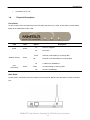
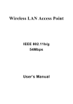
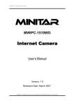
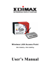
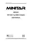
MNWAPG/MNWAPGA
Wireless 802.11b/g Access Point
User Manual
MNWAPG User Manual Copyright © 2005 Minitar Corporation
Copyright
The contents of this publication may not be reproduced in any part or as a whole, stored, transcribed
in an information retrieval system, translated into any language, or transmitted in any form or by any
means, mechanical, magnetic, electronic, optical, photocopying, manual, or otherwise, without prior
written permission.
Trademarks
All products, company, brand names are trademarks or registered trademarks of their respective
companies. They are used for identification purpose only. Specifications are subject to be changed
without prior notice.
FCC Interference Statement
This equipment has been tested and found to comply with the limits for a Class B digital device
pursuant to Part 15 of the FCC Rules. These limits are designed to provide reasonable protection
against radio interference in a commercial environment. This equipment can generate, use and
radiate radio frequency energy and, if not installed and used in accordance with the instructions in
this manual, may cause harmful interference to radio communications. Operation of this equipment
in a residential area is likely to cause interference, in which case the user, at his own expense, will
be required to take whatever measures are necessary to correct the interference.
CE Declaration of Conformity
This equipment complies with the requirements relating to electromagnetic compatibility, EN
55022/A1 Class B.
Limitation of Liability
So far as the law permits Minitar Corporation and its distributors shall not be liable in any way
whatsoever for any indirect or consequential loss, or loss of profit or any liability for damage to
property or death of or injury to persons howsoever caused including, but not limited to, any loss by
reason of delay, defective or faulty Products or workmanship, negligence or any act, matter or thing,
done permitted or omitted by Minitar Corporation and its distributors.
The specification is subject to change without notice.
MNWAPG User Manual Copyright © 2005 Minitar Corporation
Table of Contents
Chapter 1
Introduction .................................................................................................. 1
1.1 Package Contents .......................................................................................................... 2
1.2 Features ......................................................................................................................... 2
1.3 Specifications ................................................................................................................. 2
1.4 Physical Description ....................................................................................................... 3
Chapter 2
Wireless LAN Access Point Connection.................................................... 5
Chapter 3
Wireless LAN Access Point Configuration ................................................ 6
3.1 Getting Started ................................................................................................... 6
3.2 Configuring the Access Point ........................................................................... 11
Chapter 4
3.2.1
Status and Information .................................................................................... 12
3.2.2
Wireless Setting ............................................................................................... 13
3.2.3
Advanced Setting ............................................................................................ 26
3.2.4
Security ............................................................................................................ 29
3.2.5
MAC Address Filtering ..................................................................................... 37
3.2.6
System Utility ................................................................................................... 39
3.2.7
Configuration Tool ........................................................................................... 43
3.2.8
Firmware Upgrade ........................................................................................... 44
3.2.9
Reset ............................................................................................................... 45
Troubleshooting ........................................................................................ 46
MNWAPG User Manual Copyright © 2005 Minitar Corporation
Introduction
Chapter 1 Introduction
The MNWAPG/MNWAPGA is an access point for IEEE 802.11g/b 2.4GHz wireless network. You can use
MNWAPG/MNWAPGA to build up a wireless LAN. Any wireless LAN station can join the wireless network by
using the “Infrastructure Mode”.
The MNWAPG/MNWAPGA supports WEP, WPA, ESSID and MAC address filter functions to consolidate
the wireless network security. With ESSID authentication, 64/128 bit WEP encryption and MAC address
filtering you can prevent unauthorized wireless stations from accessing your wireless network.
The MNWAPG/MNWAPGA’s dipole antenna is detachable by connecting to a RP-SMA connector. Users
can install a high gain antenna to the connector for better network link quality so that you can build wireless
network with more flexibility.
MNWAPG/MNWAPGA provides easy to use user interface and allows users to configuring from web
browser. Also it integrates DHCP server to provide multiple wireless and wired users to get their IP address
automatically. With the versatile of features, this product is the best choice for you to integrate your wireless
and wired network seamlessly.
MNWAPG User Manual Copyright © 2005 Minitar Corporation
1
Introduction
1.1
Package Contents
The Access Point includes the following items:
y
One Access Point
y
One Power Adapter
y
One User’s Manual
1.2
Features
y
Complies with the IEEE 802.11b/g (DSSS) 2.4GHz specification.
y
High data rate 54Mbps network speed.
y
Seamlessly integrate wireless and wired Ethernet LAN networks.
y
Auto rate fallback in case of obstacles or interferences.
y
Provide 64/128-bit WEP and WPA Data Encryption function to protect the wireless data
transmissions.
y
Built-in DHCP server supports auto IP addresses assignment.
y
Supports Web-based configuration.
1.3
Specifications
y
Standards: IEEE 802.11b/g (Wireless), IEEE 802.3 (Wired)
y
Data Rate: 54/48/36/24/18/12/11/9/6/5.5/2/1Mbps auto fallback
y
Security: 64/128-bit WEP and WPA Data Encryption
y
Frequency Band: 2.400~2.4835GHz (Industrial Scientific Medical Band)
y
Modulation: CCK@11/5.5Mbps, DQPSK@2Mbps and DBPSK@1Mbps
y
Radio Technology: Direct Sequence Spread Spectrum (DSSS)
y
Antenna: External detachable dipole antenna (with RP-SMA connector)
y
Connectors: 10/100Mbps RJ-45 x 1
y
Power: 12VDC, 0.5A
y
Transmit Power: 15dBm (Typical)
y
LEDs: Power, LAN Link/Activity, Wireless Activity
y
Dimension: 30(H) x 127(W) x 96(D) mm
y
Temperature:
Operating: 32~131°F (0~55°C)
Storage: -4~158°F(-20~70°C)
y
Humidity: 10-90% (Noncondensing)
MNWAPG User Manual Copyright © 2005 Minitar Corporation
2
Introduction
y
Certification: FCC, CE
1.4
Physical Description
Front Panel
On the Access Point’s front panel there are LED lights that inform you of the Access Point’s current status.
Below is an explanation of each LED.
LED
Color
Power
Green
Status
Lit
Power is supplied.
Off
No Power.
Flash
Wireless Activity
Description
Antenna is transmitting or receiving data.
Green
Off
On
Antenna is not transmitting or receiving data.
A valid link is established.
LAN
Green
Flash
It is transmitting or receiving data.
Link/Activity
Off
No link is established.
Back Panel
Access Point’s connection ports are located on the back panel. Below is the description of each connection
port.
MNWAPG User Manual Copyright © 2005 Minitar Corporation
3
Introduction
y
Antenna Connector
This round connection is standard Reverse SMA connector where any antennas with Reverse SMA
connector can connect to the Access Point.
y
DC Adapter Port
Insert the power jack of the power adapter into this port.
y
LAN Port
The Access Point’s LAN port is where you connect to your LAN’s network devices.
y
Reset
The Reset button allows you to do one of two things.
1) If problems occur with your Access Point, press the reset button with a pencil tip (for less than 4
seconds) and the Access Point will re-boot itself, keeping your original configurations.
2) If problems persist or you experience extreme problems or you forgot your password, press the
reset button for longer than 4 seconds and the Access Point will reset itself to the factory default
settings (warning: your original configurations will be replaced with the factory default settings).
MNWAPG User Manual Copyright © 2005 Minitar Corporation
4
Wireless LAN Access Point Connection
Chapter 2
Wireless LAN Access Point Connection
1. Locate an optimum location for the Wireless LAN Access Point.
The best location for your Access Point is usually at the center of your wireless network, with line of
sight to all of your mobile stations.
2. Connect the Wireless LAN Access Point to your router, hub or switch.
Connect one end of standard UTP cable to the Access Point’s LAN Port and connect the other end of
the cable to a switch, a router or a hub. The Access Point will then be connected to your existed wired
LAN Network.
3. Connect the DC Power Adapter to the Wireless LAN Access Point’s Power Socket.
Only use the power adapter supplied with the Access Point. Using a different adapter may damage the
product.
The Hardware Installation is completed.
MNWAPG User Manual Copyright © 2005 Minitar Corporation
5
Wireless LAN Access Point Configuration
Chapter 3
3.1
Wireless LAN Access Point Configuration
Getting Started
This Access Point provides web-based configuration tool allowing you to configure from wired or wireless
stations. Follow the instructions below to get started configuration.
From Wired Station
1. Make sure your wired station is in the same subnet with the Access Point.
The default IP Address and Sub Mask of the Access Point is:
Default IP Address: 192.168.2.1
Default Subnet: 255.255.255.0
Configure your PC to be in the same subnet with the Access Point.
1a) Windows 95/98/Me
1. Click the Start button and select Settings, then click Control Panel. The Control Panel
window will appear.
2. Double-click Network icon. The Network window will appear.
3. Check your list of Network Components. If TCP/IP is not installed, click the Add button to
install it now. If TCP/IP is installed, go to step 6.
4. In the Network Component Type dialog box, select Protocol and click Add button.
5. In the Select Network Protocol dialog box, select Microsoft and TCP/IP and then click the
OK button to start installing the TCP/IP protocol. You may need your Windows CD to
complete the installation.
6. After installing TCP/IP, go back to the Network dialog box. Select TCP/IP from the list of
Network Components and then click the Properties button.
7. Check each of the tabs and verify the following settings:
•
Bindings: Check Client for Microsoft Networks and File and printer sharing for
Microsoft Networks.
•
Gateway: All fields are blank.
•
DNS Configuration: Select Disable DNS.
•
WINS Configuration: Select Disable WINS Resolution.
•
IP Address: Select Specify an IP Address. Specify the IP Address and Subnet Mask
as following example.
MNWAPG User Manual Copyright © 2005 Minitar Corporation
6
Wireless LAN Access Point Configuration
9
IP Address: 192.168.2.3 (any IP address within 192.168.2.2~192.168.2.254 is
available, do not setup 192.168.2.1)
9
Subnet Mask: 255.255.255.0
8. Reboot the PC. Your PC will now have the IP Address you specified.
1b) Windows XP
1: Click the Start button and select Settings, then click Network Connections. The Network
Connections window will appear.
2: Double-click Local Area Connection icon. The Local Area Connection window will appear.
3: Check your list of Network Components. You should see Internet Protocol [TCP/IP] on your list.
Select it and click the Properties button.
4: In the Internet Protocol (TCP/IP) Properties window, select Obtain an IP address automatically and
Obtain DNS server address automatically as shown on the following screen.
5: Click OK to confirm the setting. Your PC will now obtain an IP address automatically
MNWAPG User Manual Copyright © 2005 Minitar Corporation
7
Wireless LAN Access Point Configuration
from your Broadband Router’s DHCP server.
Note: Please make sure that the Broadband router’s DHCP server is the only DHCP server
available on your LAN.
Once you’ve configured your PC to obtain an IP address automatically, please proceed to
Step 3.
1c) Windows 2000
1.
Click the Start button and select Settings, then click Control Panel. The Control Panel window
will appear.
2.
Double-click Network and Dial-up Connections icon. In the Network and Dial-up
Connection
window, double-click Local Area Connection icon. The Local Area Connection window will
appear.
3.
In the Local Area Connection window, click the Properties button.
4.
Check your list of Network Components. You should see Internet Protocol [TCP/IP] on
your
list. Select it and click the Properties button.
5.
In the Internet Protocol (TCP/IP) Properties window, select Use the following IP address and
specify the IP Address and Subnet mask as following.
9
IP Address: 192.168.2.3 (any IP address within 192.168.2.2~192.168.2.254 is
available, do not setup 192.168.2.1)
9
6.
Subnet Mask: 255.255.255.0
Click OK to confirm the setting. Your PC will now have the IP Address you specified.
1d) Windows NT
1.
Click the Start button and select Settings, then click Control Panel. The Control Panel window
will appear.
2.
Double-click Network icon. The Network window will appear. Select the Protocol tab from the
Network window.
3.
Check if the TCP/IP Protocol is on your list of Network Protocols. If TCP/IP is not installed, click
the Add button to install it now. If TCP/IP is installed, go to step 5.
4.
In the Select Network Protocol window, select the TCP/IP Protocol and click the Ok
start installing the TCP/IP protocol. You may need your Windows CD to
button to
complete the
installation.
5.
After you install TCP/IP, go back to the Network window. Select TCP/IP from the list of Network
Protocols and then click the Properties button.
6.
Check each of the tabs and verify the following settings:
MNWAPG User Manual Copyright © 2005 Minitar Corporation
8
Wireless LAN Access Point Configuration
•
IP Address: Select Specify an IP address. Specify the IP Address and Subnet Mask
as following example.
9
IP Address: 192.168.2.3 (any IP address within 192.168.2.2~192.168.2.254 is
available, do not setup 192.168.2.1)
9
7.
Subnet Mask: 255.255.255.0
•
DNS: Let all fields are blank.
•
WINS: Let all fields are blank.
•
Routing: Let all fields are blank.
Click OK to confirm the setting. Your PC will now have the IP Address you specified.
2. Enter 192.168.2.1 from Web Browser to get into the Access Point’s configuration tool.
3. A screen will be popped up and request you to enter user name and password. The default
user name and password is as follows.
User Name: Admin
Password: 1234
Enter the default user name and password, then press OK button directly.
4. You can start configuring the Access Point.
From Wireless Station
MNWAPG User Manual Copyright © 2005 Minitar Corporation
9
Wireless LAN Access Point Configuration
1. Make sure your wireless station is in the same subnet with the Access Point. Please refer to
the step 1 above for configuring the IP Address and Sub Mask of the wireless station.
2. Connect to the Access Point.
The Access Point’s default ESSID is “default” and the WEP Encryption function is disabled.
Make sure your wireless station is using the same ESSID as the Access Point and associate
your wireless station to the Access Point.
3. Enter 192.168.2.1 from Web Browser to get into the Access Point’s configuration tool.
4. Enter the user name and password and then press OK button and you are available to
configure the Access Point now.
MNWAPG User Manual Copyright © 2005 Minitar Corporation
10
Wireless LAN Access Point Configuration
3.2
Configuring the Access Point
Every time when you have finished modifying a setting page and click “Apply” button, this page will pop-up.
The settings have been successfully saved but will not take effect immediately. You have to restart the
access point to make the new settings take effect. You can click “CONTINUE” button to continue other
settings. You also can click “APPLY” to restart the system and make the settings take effect.
MNWAPG User Manual Copyright © 2005 Minitar Corporation
11
Wireless LAN Access Point Configuration
3.2.1
Status and Information
On this screen, you can see the general information of the Access Point including Alias Name, Firmware
Version, ESSID, Channel Number, Status, IP Address, MAC Address, etc.
MNWAPG User Manual Copyright © 2005 Minitar Corporation
12
Wireless LAN Access Point Configuration
3.2.2
Wireless Setting
This MNWAPG/MNWAPGA supports AP, Station, Bridge, WDS and Universal Repeater modes. “AP Mode”
provides pure access point function. The simplest way to build up a wireless LAN is to use “AP Mode”.
“Station Mode” is used to let a network device with only wired Ethernet function to have wireless LAN
communication capability. It provides both Ad Hoc and Infrastructure modes for the “Station Mode”. With
“Station-Ad Hoc mode”, it can let your network device join a wireless LAN with peer-to-peer communication.
With “Station-Infrastructure mode”, it can let your network device join a wireless LAN through an access point.
“AP Bridge Mode” provides the function to bridge more than 2 wired Ethernet networks together by wireless
LAN. You can use two access points with “AP Bridge-Point to Point mode” to bridge two wired Ethernet
networks together. If you want to bridge more than two wired Ethernet networks together, you have to use
enough access points with “AP Bridge-Point to Multi-Point mode”. An access point with “AP Bridge-Point to
Point mode” or “AP Bridge-Point to Multi-Point mode” can only be used to bridge wired Ethernet networks
together. It can’t accept connection from other wireless station at the same time. If you want an access point
to bridge wired Ethernet network and provide connection service for other wireless station at the same time,
you have to set the access point to “AP Bridge-WDS mode”. Simply speaking, “AP Bridge-WDS mode”
function is the combination of “AP mode” and “AP Bridge-Point to Multi-Point mode”. “Universal Repeater
Mode” provides the function to act as AP client and AP at the same time. It can use AP client function to
connect to a Root AP and use AP function to service all wireless stations within its coverage. All the stations
within the coverage of this access point can be bridged to the Root AP. “Universal Repeater Mode” is very
convenient to extend the coverage of your wireless network.
MNWAPG User Manual Copyright © 2005 Minitar Corporation
13
Wireless LAN Access Point Configuration
AP mode setting page:
MNWAPG User Manual Copyright © 2005 Minitar Corporation
14
Wireless LAN Access Point Configuration
Station-Ad Hoc mode setting page:
MNWAPG User Manual Copyright © 2005 Minitar Corporation
15
Wireless LAN Access Point Configuration
Station-Infrastructure mode setting page:
MNWAPG User Manual Copyright © 2005 Minitar Corporation
16
Wireless LAN Access Point Configuration
AP Bridge-Point to Point mode setting page:
MNWAPG User Manual Copyright © 2005 Minitar Corporation
17
Wireless LAN Access Point Configuration
AP Bridge-Point to Multi-Point mode setting page:
MNWAPG User Manual Copyright © 2005 Minitar Corporation
18
Wireless LAN Access Point Configuration
AP Bridge-WDS mode setting page:
MNWAPG User Manual Copyright © 2005 Minitar Corporation
19
Wireless LAN Access Point Configuration
Universal Repeater mode setting page:
Parameter
Description
ESSID
The ESSID (up to 31 printable ASCII characters) is the unique name
identified in a WLAN. The ID prevents the unintentional merging of two
co-located WLANs. Please make sure that the ESSID of all stations in
the same WLAN network are the same. The default ESSID is “default”.
You should assign ESSID in “AP mode”, “Station-Ad Hoc mode”,
“Station-Infrastructure mode”, “AP Bridge-WDS mode” and “Universal
Repeater mode”.
Band
It allows you to set the AP fix at 802.11b or 802.11g mode. You also can
select B+G mode to allow the AP select 802.11b and 802.11g connection
automatically.
Channel Number
Select the appropriate channel from the list provided to correspond with
your network settings. Channels differ from country to country.
Channel 1-11 (North America)
MNWAPG User Manual Copyright © 2005 Minitar Corporation
20
Wireless LAN Access Point Configuration
Channel 1-14 (Japan)
Channel 1-13 (Europe)
There are 14 channels available.
You should assign Channel Number in “AP mode”, “Station-Ad Hoc
mode”, “AP Bridge-Point to Point mode”, “AP Bridge-Point to Multi-Point
mode” and “AP Bridge-WDS mode”, “Universal Repeater mode”.
MAC Address
If you want to bridge more than one wired Ethernet networks together
with wireless LAN, you have to set this access point to “AP Bridge-Point
to Point mode”, “AP Bridge-Point to Multi-Point mode” or “AP BridgeWDS mode”. You have to enter the MAC addresses of other access
points that join the bridging work.
WLAN MAC
In “Station-Ad Hoc mode”, “Station-Infrastructure mode” and “Universal
Repeater mode”, this device need a WLAN MAC address to act as a
station to connect to other peer or access point. You also can click
“Clone MAC” button to let this device copy the MAC address of the PC
you are using to configure this device.
Root AP SSID
In “Universal Repeater mode”, this device can act as a station to connect
to a Root AP. You should assign the SSID of the Root AP here.
Set Security
In “AP Bridge-Point to Point mode”, ““AP Bridge-Point to Multi-Point
mode” and “AP Bridge-WDS mode”, you can click “Set Security” to add
encryption for the communication between the bridged access points.
This can protect your wireless network.
Associated Clients
Click “Show Active Clients” button, then an “Active Wireless Client Table”
will pop up. You can see the status of all active wireless stations that are
connecting to the access point.
Wireless Site Survey
When you use this access point as a wireless station for wired network
device to have wireless capability, you have to associate it will an
working access point. Click “Select Site Survey” button, then a “Wireless
Site Survey Table” will pop up. It will list all available access points near
by. You can select one access point in the table and it will join wireless
LAN through this access point.
Click Apply button at the bottom of the screen to save the above configurations. You can now configure
other advance sections or start using the Access Point.
MNWAPG User Manual Copyright © 2005 Minitar Corporation
21
Wireless LAN Access Point Configuration
Set Security
“Set Security” let you setup the wireless security for the data transmission between the bridged access points
in “AP Bridge-Point to Point mode”, “AP Bridge-Point to Multi-Point mode” or “AP Bridge-WDS mode”. It
provides “WEP 64bits”, “WEP 128bits”, “WPA (TKIP)”, “WPA2 (AES)” encryption methods.
Parameter
Description
Encryption
You can select “No encryption”,“WEP 64bits”, “WEP 128bits”, “WPA
(TKIP)” or “WPA2 (AES)” encryption methods.
Key Format
This is only used when you select “WEP 64bits” or “WEP 128bits”
encryption method. You may select to select ASCII Characters
(alphanumeric format) or Hexadecimal Digits (in the “A-F”, “a-f” and “0-9”
range) to be the WEP Key. For example:
ASCII Characters: guest
Hexadecimal Digits: 12345abcde
MNWAPG User Manual Copyright © 2005 Minitar Corporation
22
Wireless LAN Access Point Configuration
WEP Key
This is only used when you select “WEP 64bits” or “WEP 128bits”
encryption method. The WEP key is used to encrypt data transmitted
between the bridged access points. Fill the text box by following the rules
below.
64-bit WEP: input 10-digit Hex values (in the “A-F”, “a-f” and “0-9” range)
or 5-digit ASCII character as the encryption keys.
128-bit WEP: input 26-digit Hex values (in the “A-F”, “a-f” and “0-9”
range) or 10-digit ASCII characters as the encryption keys.
Pre-shared Key Format
You may select to select Passphrase (alphanumeric format) or
Hexadecimal Digits (in the “A-F”, “a-f” and “0-9” range) to be the Preshared Key. For example:
Passphrase: iamguest
Hexadecimal Digits: 12345abcde
Pre-shared Key
The Pre-shared key is used to authenticate and encrypt data transmitted
between the bridged access points. Fill the text box by following the rules
below. Hex WEP: input 64-digit Hex values (in the “A-F”, “a-f” and “0-9”
range) or at least 8 character pass phrase as the pre-shared keys.
Click Apply button at the bottom of the screen to save the above configurations. You can now configure
other advance sections or start using the Access Point.
Active Wireless Client Table
“Active Wireless Client Table” records the status of all active wireless stations that are connecting to the
access point. You can lookup the MAC Address, Number of Transmitted Packets, Number of Received
Packets and Encryption Status of each active wireless client in this table.
MNWAPG User Manual Copyright © 2005 Minitar Corporation
23
Wireless LAN Access Point Configuration
Parameter
Description
MAC Address
MAC address of this active wireless station.
Tx Packet
The number of transmitted packets that are sent out from this active
wireless station.
Rx Packet
The number of received packets that are received by this active wireless
station.
TX Rate
The transmission rate in Mbps.
Power Saving
Shows if the wireless client is in Power Saving mode.
Expired Time
The time in second before dissociation. If the wireless keeps idle long
than the expired time, this access point will dissociate it. The wireless
client station has to associate again when it become active.
Refresh
Refresh the “Active Wireless Client Table”.
MNWAPG User Manual Copyright © 2005 Minitar Corporation
24
Wireless LAN Access Point Configuration
Close
Refresh the “Active Wireless Client Table”.
Wireless Site Survey
When this access point is in “Station-Ad Hoc mode”, “Station-Infrastructure mode” or “Universal Repeater
mode”, it should associate with an access point or station and connect to your wireless LAN through the
associated access point or station. “Wireless Site Survey” searches for all available access points near by.
You can select one access point listed in this table.
MNWAPG User Manual Copyright © 2005 Minitar Corporation
25
Wireless LAN Access Point Configuration
3.2.3
Advanced Setting
You can set advanced parameters of this access point. The parameters include Authentication Type,
Fragment Threshold, RTS Threshold, Beacon Interval, Tx Operation Rate, Tx Basic Rate, Preamble Type,
Broadcast ESSID. You should not change these parameters unless you know what effect the changes will
have on this access point.
Parameter
Description
Authentication Type
There are two authentication types: “Open System” and “Shared Key”.
When you select “Open System”, wireless stations can associate with
this access point without WEP encryption. When you select “Shared
Key”, you should also setup WEP key in the “Encryption” page and
wireless stations should use WEP encryption in the authentication phase
to associate with this access point. If you select “Auto”, the wireless client
can associate with this access point by using any one of these two
authentication types.
MNWAPG User Manual Copyright © 2005 Minitar Corporation
26
Wireless LAN Access Point Configuration
Fragment Threshold
“Fragment Threshold” specifies the maximum size of packet during the
fragmentation of data to be transmitted. If you set this value too low, it will
result in bad performance.
RTS Threshold
When the packet size is smaller than the RTS threshold, the access point
will not use the RTS/CTS mechanism to send this packet.
Beacon Interval
The interval of time that this access point broadcast a beacon. Beacon is
used to synchronize the wireless network.
Data Rate
The “Data Rate” is the rate this access point uses to transmit data
packets. The access point will use the highest possible selected
transmission rate to transmit the data packets.
Preamble Type
Preamble type defines the length of CRC block in the frames during the
wireless communication. “Short Preamble” is suitable for high traffic
wireless network. “Long Preamble” can provide more reliable
communication.
Broadcast ESSID
If you enable “Broadcast ESSID”, every wireless station located within
the coverage of this access point can discover this access point easily. If
you are building a public wireless network, enabling this feature is
recommended. Disabling “Broadcast ESSID” can provide better security.
IAPP
If you enable “IAPP”, the access point will automatically broadcast
information of associated wireless stations to its neighbors. This will help
wireless station roaming smoothly between access points. If you have
more than one access points in your wireless LAN and wireless stations
have roaming requirements, enabling this feature is recommended.
Disabling “IAPP” can provide better security.
802.11g Protection
This is also called CTS Protection. It is recommended to enable the
protection mechanism. This mechanism can decrease the rate of data
collision between 802.11b and 802.11g wireless stations. When the
protection mode is enabled, the throughput of the AP will be a little lower
due to many of frame traffic should be transmitted.
MNWAPG User Manual Copyright © 2005 Minitar Corporation
27
Wireless LAN Access Point Configuration
Click Apply button at the bottom of the screen to save the above configurations. You can now configure
other advance sections or start using the Access Point.
MNWAPG User Manual Copyright © 2005 Minitar Corporation
28
Wireless LAN Access Point Configuration
3.2.4
Security
This Access Point provides complete wireless LAN security functions, include WEP, IEEE 802.11x, IEEE
802.11x with WEP, WPA with pre-shared key and WPA with RADIUS. With these security functions, you can
prevent your wireless LAN from illegal access. Please make sure your wireless stations use the same
security function.
Note: This access point can act as station and AP at the same time in “Universal Repeater mode”. The
security settings only apply to AP function in “Universal Repeater mode”. The station function of “Universal
Repeater mode” does not have security feature.
WEP only
When you select 64-bit or128-bit WEP key, you have to enter WEP keys to encrypt data. You can generate
the key by yourself and enter it. You can enter four WEP keys and select one of them as default key. Then
the access point can receive any packets encrypted by one of the four keys. You can use WEP encryption in
“AP mode”, “Station-Ad Hoc mode”, “Station-Infrastructure mode”, “AP Bridge-WDS mode” and “Universal
Repeater mode”.
MNWAPG User Manual Copyright © 2005 Minitar Corporation
29
Wireless LAN Access Point Configuration
Parameter
Description
Key Length
You can select the 64 or 128-bit key to encrypt transmitted data. Larger
WEP key length will provide higher level of security, but the throughput
will be lower.
Key Format
You may select to select ASCII Characters (alphanumeric format) or
Hexadecimal Digits (in the “A-F”, “a-f” and “0-9” range) to be the WEP
Key. For example:
ASCII Characters: guest
Hexadecimal Digits: 12345abcde
Default Tx Key
Select one of the four keys to encrypt your data. Only the key you select
it in the “Default key” will take effect.
Key 1 - Key 4
The WEP keys are used to encrypt data transmitted in the wireless
network. Fill the text box by following the rules below.
MNWAPG User Manual Copyright © 2005 Minitar Corporation
30
Wireless LAN Access Point Configuration
64-bit WEP: input 10-digit Hex values (in the “A-F”, “a-f” and “0-9” range)
or 5-digit ASCII character as the encryption keys.
128-bit WEP: input 26-digit Hex values (in the “A-F”, “a-f” and “0-9”
range) or 10-digit ASCII characters as the encryption keys.
Click Apply button at the bottom of the screen to save the above configurations. You can now configure
other advance sections or start using the Access Point.
802.1x only
IEEE 802.1x is an authentication protocol. Every user must use a valid account to login to this Access Point
before accessing the wireless LAN. The authentication is processed by a RADIUS server. This mode only
authenticates user by IEEE 802.1x, but it does not encryption the data during communication. You can use
802.1x without encryption in “AP mode”, “AP Bridge-WDS mode” and “Universal Repeater mode”.
Parameter
Description
RADIUS Server IP address
The IP address of external RADIUS server.
MNWAPG User Manual Copyright © 2005 Minitar Corporation
31
Wireless LAN Access Point Configuration
RADIUS Server Port
The service port of the external RADIUS server.
RADIUS Server Password
The password used by external RADIUS server.
Click Apply button at the bottom of the screen to save the above configurations. You can now configure
other advance sections or start using the Access Point.
802.1x WEP static key
IEEE 802.1x is an authentication protocol. Every user must use a valid account to login to this Access Point
before accessing the wireless LAN. The authentication is processed by a RADIUS server. This mode also
uses WEP to encrypt the data during communication. You can use 802.1x with WEP encryption in “AP
mode”, “AP Bridge-WDS mode” and “Universal Repeater mode”.
For the WEP settings, please refer to section “WEP only”. For the 802.1x settings, please refer to section
“802.1x only”.
MNWAPG User Manual Copyright © 2005 Minitar Corporation
32
Wireless LAN Access Point Configuration
Click Apply button at the bottom of the screen to save the above configurations. You can now configure
other advance sections or start using the Access Point.
WPA pre-shared key
Wi-Fi Protected Access (WPA) is an advanced security standard. You can use a pre-shared key to
authenticate wireless stations and encrypt data during communication. It uses TKIP or CCMP(AES) to
change the encryption key frequently. So the encryption key is not easy to be broken by hackers. This can
improve security very much. You can use WPA pre-shared key encryption in “AP mode”, “Station-Ad Hoc
mode”, “Station-Infrastructure mode”, “AP Bridge-WDS mode” and “Universal Repeater mode”.
Parameter
Description
WPA(TKIP)
TKIP can change the encryption key frequently to enhance the wireless
LAN security.
WPA2(AES)
This use CCMP protocol to change encryption key frequently. AES can
provide high level encryption to enhance the wireless LAN security.
MNWAPG User Manual Copyright © 2005 Minitar Corporation
33
Wireless LAN Access Point Configuration
WPA2 Mixed
This will use TKIP or AES based on the other communication peer
automatically.
Pre-shared Key Format
You may select to select Passphrase (alphanumeric format) or
Hexadecimal Digits (in the “A-F”, “a-f” and “0-9” range) to be the Preshared Key. For example:
Passphrase: iamguest
Hexadecimal Digits: 12345abcde
Pre-shared Key
The Pre-shared key is used to authenticate and encrypt data transmitted
in the wireless network. Fill the text box by following the rules below.
Hex: input 64-digit Hex values (in the “A-F”, “a-f” and “0-9” range) or at
least 8 character pass phrase as the pre-shared keys.
Click Apply button at the bottom of the screen to save the above configurations. You can now configure
other advance sections or start using the Access Point.
WPA RADIUS
Wi-Fi Protected Access (WPA) is an advanced security standard. You can use an external RADIUS server to
authenticate wireless stations and provide the session key to encrypt data during communication. It uses
TKIP or CCMP(AES) to change the encryption key frequently. This can improve security very much. You can
use WPA RADIUS encryption in “AP mode”, “AP Bridge-WDS mode” and “Universal Repeater mode”.
MNWAPG User Manual Copyright © 2005 Minitar Corporation
34
Wireless LAN Access Point Configuration
Parameter
Description
WPA(TKIP)
TKIP can change the encryption key frequently to enhance the wireless
LAN security.
WPA2(AES)
This use CCMP protocol to change encryption key frequently. AES can
provide high level encryption to enhance the wireless LAN security.
WPA2 Mixed
This will use TKIP or AES based on the other communication peer
automatically.
RADIUS Server IP address
The IP address of external RADIUS server.
RADIUS Server Port
The service port of the external RADIUS server.
RADIUS Server Password
The password used by external RADIUS server.
MNWAPG User Manual Copyright © 2005 Minitar Corporation
35
Wireless LAN Access Point Configuration
Click Apply button at the bottom of the screen to save the above configurations. You can now configure
other advance sections or start using the Access Point.
MNWAPG User Manual Copyright © 2005 Minitar Corporation
36
Wireless LAN Access Point Configuration
3.2.5
MAC Address Filtering
This Access Point provides MAC Address Filtering, which prevents the unauthorized MAC Addresses from
accessing your wireless network.
Parameter
Description
Enable Wireless Access Control
Enable or disable the MAC Address Filtering function.
MAC Address Filtering Table
This table records the MAC addresses of wireless stations you want to
allow to access your network. The “Comment” field is the description of
the wireless station associated with the “MAC Address” and is helpful for
you to recognize the wireless station.
Add MAC address into the table
In the bottom “New” area, fill in the “MAC Address” and “Comment” of the
wireless station to be added and then click “Add”. Then this wireless
station will be added into the “MAC Address Filtering Table” above. If you
MNWAPG User Manual Copyright © 2005 Minitar Corporation
37
Wireless LAN Access Point Configuration
find any typo before adding it and want to retype again. Just click “Clear”
and both “MAC Address” and “Comment” fields will be cleared.
Remove MAC address from the
If you want to remove some MAC address from the “MAC Address
table
Filtering Table”, select the MAC addresses you want to remove in the
table and then click “Delete Selected”. If you want remove all MAC
addresses from the table, just click “Delete All” button.
Reset
Click “Reset” will clear your current selections.
Click Apply button at the bottom of the screen to save the above configurations. You can now configure
other advance sections or start using the Access Point.
MNWAPG User Manual Copyright © 2005 Minitar Corporation
38
Wireless LAN Access Point Configuration
3.2.6
System Utility
From here, you can define the Access Point’s IP Address and Login Password and enable the Access Point
to be a DHCP Server.
Parameter
Description
Current Password
Enter the current password (up to 15-digit alphanumeric string) of the
Access Point. The default password for the Access Point is 1234. Note
that the password is case-sensitive.
New Password
Enter the password (up to 15-digit alphanumeric string) you want to login
to the Access Point. Note that the password is case-sensitive.
Re-Enter Password
Reconfirm the password (up to 15-digit alphanumeric string) you want to
login to the Access Point. Note that the password is case-sensitive.
MNWAPG User Manual Copyright © 2005 Minitar Corporation
39
Wireless LAN Access Point Configuration
IP Address
Designate the Access Point’s IP Address. This IP Address should be
unique in your network. The default IP Address is 192.168.2.1.
Subnet Mask
Specify a Subnet Mask for your LAN segment. The Subnet Mask of the
Access Point is fixed and the value is 255.255.255.0.
Gateway Address
The IP address of the default gateway of the subnet that this access point
resides in. It allows this access point be accessed by PC from deferent
subnet to do configuration.
DHCP Server
Enable or disable the DHCP Server.
Click Apply button at the bottom of the screen to save the above configurations. You can now configure
other advance sections or start using the Access Point.
DHCP Server Setting
DHCP Server will automatically give your LAN client an IP address. If the DHCP is not enabled then you’ll
have to manually set your LAN client’s IP address.
MNWAPG User Manual Copyright © 2005 Minitar Corporation
40
Wireless LAN Access Point Configuration
Parameter
Description
Default Gateway IP
Specify the gateway IP in your network. This IP address should be
different from the Management IP.
Domain Name Server IP
This is the ISP’s DNS server IP address that they gave you; or you can
specify your own preferred DNS server IP address.
Start IP/End IP
You can designate a particular IP address range for your DHCP server to
issue IP addresses to your LAN Clients. By default the IP range is from:
Start IP 192.168.2.100 to End IP 192.168.2.200.
Domain Name
You can specify the Domain Name for your Access Point.
Lease Time
The DHCP Server when enabled will temporarily give your LAN client an
IP address. In the Lease Time setting you can specify the time period
that the DHCP Server lends an IP address to your LAN clients. The
DHCP Server will change your LAN client’s IP address when this time
threshold period is reached.
MNWAPG User Manual Copyright © 2005 Minitar Corporation
41
Wireless LAN Access Point Configuration
Click Apply button at the bottom of the screen to save the above configurations. You can now configure
other advance sections or start using the Access Point.
MNWAPG User Manual Copyright © 2005 Minitar Corporation
42
Wireless LAN Access Point Configuration
3.2.7
Configuration Tool
The Configuration Tools screen allows you to save (Backup) the Access Point’s current configuration setting.
Saving the configuration settings provides an added protection and convenience should problems occur with
the Access Point and you have to reset to factory default. When you save the configuration setting (Backup)
you can re-load the saved configuration into the Access Point through the Restore selection. If extreme
problems occur you can use the Restore to Factory Default selection, this will set all configurations to its
original default settings (e.g. when you first purchased the Access Point).
Parameter
Description
Configuration Tools
Use the "Backup" tool to save the Access Point’s current configuration to
a file named "config.bin" on your PC. You can then use the "Restore"
tool to upload and restore the saved configuration to the Access Point.
Alternatively, you can use the "Restore to Factory Default" tool to force
the Access Point to perform a power reset and restore the original factory
settings.
MNWAPG User Manual Copyright © 2005 Minitar Corporation
43
Wireless LAN Access Point Configuration
3.2.8
Firmware Upgrade
This page allows you to upgrade the Access Point’s firmware.
Parameter
Description
Firmware Upgrade
This tool allows you to upgrade the Access Point’s system firmware. To
upgrade the firmware of your Access Point, you need to download the
firmware file to your local hard disk, and enter that file name and path in
the appropriate field on this page. You can also use the Browse button to
find the firmware file on your PC. Please reset the Access Point when the
upgrade process is complete.
Once you’ve selected the new firmware file, click Apply button at the bottom of the screen to start the
upgrade process. (You may have to wait a few minutes for the upgrade to complete). Once the upgrade is
complete you can start using the Access Point.
MNWAPG User Manual Copyright © 2005 Minitar Corporation
44
Wireless LAN Access Point Configuration
3.2.9
Reset
You can reset the Access Point’s system should any problem exist. The reset function essentially Re-boots
your Access Point’s system.
Parameter
Description
Reset
In the event that the system stops responding correctly or in some way
stops functioning, you can perform a reset. Your settings will not be
changed. To perform the reset, click on the Apply button. You will be
asked to confirm your decision. Once the reset process is complete you
may start using the Access Point again.
MNWAPG User Manual Copyright © 2005 Minitar Corporation
45
Troubleshooting
Chapter 4
Troubleshooting
This chapter provides solutions to problems usually encountered during the installation and operation of the
Access Point.
1.
How to manually find your PC’s IP and MAC Address?
1) In Windows, open the Command Prompt program
2) Type Ipconfig /all and Enter
2.
y
Your PC’s IP address is the one entitled IP address
y
Your PC’s MAC Address is the one entitled Physical Address
What is Ad-hoc?
An Ad-hoc wireless LAN is a group of computers, each with a WLAN adapter, connected as an
independent wireless LAN.
3.
What is Infrastructure?
An integrated wireless and wired LAN is called an Infrastructure configuration.
4.
What is BSS ID?
A group of wireless stations and an Access Point compose a Basic Service Set (BSS). Computers in a
BSS must be configured with the same BSSID.
5.
What is ESSID?
An Infrastructure configuration could also support roaming capability for mobile workers. More than one
BSS can be configured as an Extended Service Set (ESS). Users within an ESS could roam freely
between BSSs while maintaining a continuous connection to the wireless network stations and the
Wireless LAN Access Points.
6.
Can data be intercepted while transmitting through the air?
WLAN features two-fold protection in security. On the hardware side, as with Direct Sequence Spread
Spectrum technology, it has the inherent scrambling security feature. On the software side, the WLAN
series offers the encryption function (WEP, WPA, WPA2) to enhance security and access control.
7.
What is WEP?
MNWAPG User Manual Copyright © 2005 Minitar Corporation
46
Troubleshooting
WEP stands for Wired Equivalent Privacy, a data privacy mechanism based on a 64(40)-bit shared key
algorithm.
8.
What is WPA?
WPA is an acronym for Wi-Fi Protected Access. It is a security protocol for 802.11 wireless networks.
WPA can provide data protection with the use of encryption and the use of access controls and user
authentication.
9.
What is WPA2?
In addition to WPA, WPA2 provides a stronger encryption mechanism through Advanced Encryption
Standard (AES).
10.
What is a MAC Address?
The Media Access Control (MAC) address is a unique number assigned by the manufacturer to any
Ethernet networking device, such as a network adapter, that allows the network to identify it at the
hardware level. For all practical purposes, this number is usually permanent. Unlike IP addresses,
which can change every time a computer logs on to the network, the MAC address of a device stays
the same, making it a valuable identifier for the network.
MNWAPG User Manual Copyright © 2005 Minitar Corporation
47
Troubleshooting
Federal Communication Commission Interference Statement
This equipment has been tested and found to comply with the limits for a Class B digital device,
pursuant to Part 15 of the FCC Rules. These limits are designed to provide reasonable protection
against harmful interference in a residential installation. This equipment generates, uses and can
radiate radio frequency energy and, if not installed and used in accordance with the instructions, may
cause harmful interference to radio communications.
However, there is no guarantee that
interference will not occur in a particular installation.
If this equipment does cause harmful
interference to radio or television reception, which can be determined by turning the equipment off
and on, the user is encouraged to try to correct the interference by one of the following measures:
-
Reorient or relocate the receiving antenna.
-
Increase the separation between the equipment and receiver.
-
Connect the equipment into an outlet on a circuit different from that
to which the receiver is connected.
-
Consult the dealer or an experienced radio/TV technician for help.
FCC Caution: Any changes or modifications not expressly approved by the party responsible for
compliance could void the user's authority to operate this equipment.
This device complies with Part 15 of the FCC Rules. Operation is subject to the following two
conditions: (1) This device may not cause harmful interference, and (2) this device must accept any
interference received, including interference that may cause undesired operation.
IMPORTANT NOTE:
FCC Radiation Exposure Statement:
This equipment complies with FCC radiation exposure limits set forth for an uncontrolled
environment. This equipment should be installed and operated with minimum distance 20cm
between the radiator & your body.
This transmitter must not be co-located or operating in conjunction with any other antenna or
transmitter.
MNWAPG User Manual Copyright © 2005 Minitar Corporation
48