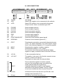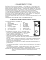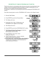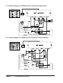
1
COSTRUZIONE APPARECCHIATURE ELETTRONICHE - OLEODINAMICHE - INDUSTRIALI
42028 - POVIGLIO - (R.E.) - Via Parma, 59 - ITALIA
Tel. (0522) 960050 (r.a.) - Tlx. 530021 AINDRE I - Fax (0522) 960259
ZAPIMOS H2B
USER'S
MANU
AL
MANUA
CONTENTS
Page
Legend
.............................................................................................................. 3
1 Introduction to the ZAPIMOS family ............................................................ 4
2 General H2B characteristics ........................................................................ 5
2.1 Technical specifications ........................................................................ 5
2.2 Control unit ............................................................................................ 6
2.2a Microswitches ............................................................................... 6
2.2b Potentiometer ............................................................................... 6
2.3 Protection features ................................................................................ 8
2.4 Performance features ............................................................................ 9
2.5 H2B chopper diagnosis ......................................................................... 9
2.6 Thermal considerations ......................................................................... 9
2.7 General notes and precautions
................................................... 10
.... 11
2.8 General contactors and safety switch for regenerative model
3 Installation ................................................................................................... 12
3.1 Choosing connection cables ............................................................... 12
3.2 Contactors ........................................................................................... 12
3.3 Fuses .................................................................................................. 12
3.4 H2B connectors ................................................................................... 13
3.5 H2B power connectors ........................................................................ 14
3.6 Contactors connector .......................................................................... 15
3.7 H2B chopper mechanical drawing....................................................... 16
4 Parameter modifications ............................................................................ 17
4.1 Modifying parameters using the mini-console ..................................... 17
4.2 Modifying parameters using the digital-console .................................. 18
4.3 Chopper configuration and connections description ........................... 20
5 Traction ........................................................................................................ 22
5.1 H2B regenerative traction ................................................................... 22
5.1.1 Input connectors description ..................................................... 23
5.1.2 Programmable functions (options) ............................................ 24
5.1.3 Parameter modification ............................................................. 26
5.1.4 Adjustment chart ....................................................................... 27
Variants for braking soft ............................................................ 27
5.1.5 Wiring diagram for H2B regenerative model with pedal ............ 28
5.1.6 Wiring diagram for H2B regenerative model with handle .......... 28
5.1.7 Wiring diagram for H2B regenerative model with
speed check and pick-up.......................................................... 29
5.1.8 Wiring diagram for H2B regenerative model with speed check
and tacho-generator .................................................................. 30
5.1.9 Wiring diagram for H2B regenerative model with speed
check and backing..................................................................... 31
5.1.10 Wiring diagram for H2B regenerative model power unit ......... 32
5.1.11 Wiring diagram for H2B regenerative model power unit
with weakening ........................................................................ 33
5.1.12 Wiring diagram for H2B power unit regenerative with bypass. 34
5.1.13 Wiring diagram for H2B power unit regenerative with
weakening ............................................................................... 34
5.2 H2B standard traction.......................................................................... 35
5.2.1 Input connectors ........................................................................ 36
5.2.2 Programmable function (options) .............................................. 36
5.2.3 Parameter modification (traction) .............................................. 37
5.2.4 Adjustment chart ....................................................................... 37
H2B
Page 1
6
7
8
Page
5.2.5 Wiring diagram for H2B standard traction with pedal ................ 38
5.2.6 Wiring diagram for H2B standard traction with handle .............. 38
5.2.7 Wiring diagram for H2B power unit standard traction
with weakening .......................................................................... 39
5.2.8 Wiring diagram for H2B power standard with 5 cables motor ... 39
5.3 Sequence of settings for regenerative / standard traction ................... 40
5.4 H2B traction diagnosis ........................................................................ 41
5.5 Decoding console displayed alarms .................................................... 42
Pump ............................................................................................................ 50
6.1 H2B standard lifting ............................................................................. 50
6.1.1 Input connectors ........................................................................ 51
6.1.2 Programmable functions (options) ............................................ 52
6.1.3 Parameter modification ............................................................. 52
6.1.4 Adjustment chart ....................................................................... 54
6.1.5 Connection diagram for H2B standard lifting............................. 55
6.1.6 Connection diagram for H2B pump unit with weakening ........... 55
6.1.7 Connection diagram for H2B, with power unit bypass
contactor and main contactor .................................................... 56
6.1.8 H2B power unit standard connection diagram .......................... 56
6.2 H2B lifting + 3rd motor ........................................................................ 57
6.2.1 Input connectors ........................................................................ 58
6.2.2 Programmable functions (options) ............................................ 58
6.2.3 Parameter modification ............................................................. 58
6.2.4 H2B electrical connection diagrams pump + hydro ................... 59
6.2.5 H2B power unit wiring lifting + hydrodrive + weakening ............ 59
6.3 Sequence of settings for lifting ............................................................ 60
6.4 Setting the proportional solenoid valve ............................................... 60
6.5 H2B lifting diagnosis ............................................................................ 61
6.5.1 Decoding the alarms displayed on console ............................... 61
Recommended spare parts for H2B .......................................................... 64
Maintenance................................................................................................. 65
=
The informations included into the marked paragraphs by this symbol are
essential for the safety.
APPROVAL SIGNATURES
COMPANY DEPT. SERVICES
ENGINEERING SECTION EXECUTIVE
EXPORT MANAGER
Pubblication n. : 550145D
Edition : September 1995
Page 2
H2B
MANAGEMENT EXECUTIVE
LEGEND
1^V
= 1st lift speed request
AV
= Forward
CH
= Key
DF
= Brake diode
DV
= Flywheel diode
IN
= Backward
IND
= Weakening
MA
= Forward speed microswitch
MCL = Horn microswitch
MD
= Descent microswitch
MEF = Electric brake switch
MI
= Backward microswitch
MS
= Rise microswitch
MT
= Handle microswitch
MUM = Dead man microswitch
NT
= Contactor negative
RV
= Speed reduction
VMN = Negative motor voltage
H2B
Page 3
1 INTRODUCTION TO THE ZAPIMOS FAMILY
The ZAPIMOS chopper family is ZAPI’s answer to the needs of users of the ’90s.
To ensure that the product stays on the market without running the risk of becoming
technologically obsolete, ZAPI has designed the ZAPIMOS family to offer the following
features:
- Advanced technology and economical costs
- Maximum safety
- Maximum flexibility
- Open to future technological innovations
- Optimum level of protection.
This implies:
- High frequency Mos technology
- Real-time control over the internal and external parts that can influence the behaviour of the machine, with self-diagnosis of the checking circuits themselves.
- Stored programme machine (SPC) where the hardware is completely separate from
the functions to be configured. The programme is parametric and can also be modified by the final user.
- Various chopper functional configurations can be selected by the user, without the
need for hardware modifications.
- Any future technological updates are made clear to the user.
The communication protocol will continue to evolve, thus offering increasing possibilities of interaction.
For this reason, the ZAPIMOS family offers a standard dialogue mode with external
systems, for easy interfacing with commercially available machines. ZAPI offers a
range of programming consoles with various features and prices.
- Logic and power units are fitted in a sealed container (IP54), to guarantee protection
against splashes (water, acid, etc.) and dust, chips, or small particles.
Access to the logic for replacement or checks, however, is very easy.
- The H2B chopper is the top-of-the-line model of the Zapimos family. It is suitable for
operating at voltages from 24 to 96 V with maximum currents of 400 or 600 amp.
Suitable for use with series motors with powers from 2000 W to 15 kW.
Page 4
H2B general description
2 GENERAL H2B CHARACTERISTICS
2.1 TECHNICAL SPECIFICATIONS
Voltage:
........................................................................................ 24V (14 ÷ 32V)
........................................................................... 36 / 40 / 48V (22 ÷ 55V)
........................................................................... 60 / 72 / 80V (36 ÷ 90V)
...................................................................................... 96V (57 ÷ 120V)
Maximum current: ......................................................................... short size = 400 A
.................................................... long size = 600 A (80 V model: 500 A)
SYSTEM
VOLTAGE
H2 400
(SHORT)
H2 600
(LONG)
H2 601
24V
400A
600A
/
48V
400A
600A
/
80V
400A
/
500A / 600A
96V
400A
/
500A / 600A
Frequency: .................................................................................................... 16 kHz
Motors (characteristics): ............................................. DC wire wound serie 4 cables
Operating ambient temperature: ........................................................... -30 to +40°C
Maximum allowable temperature for chopper body: ......................................... 85°C
Drop voltage with I=200 A:
SYSTEM
VOLTAGE
H2 400
(SHORT)
H2 600
(LONG)
H2 601
24V
250mV
200mV
/
48V
350mv
280mV
/
80V
1.00V
550mV
550mV
Microprocessor logic unit.
4 different configurations that can be set from the console:
1 traction control and energy regeneration
2
5-speed pump control
3
4-speed pump control + hydrodrive contactor handling
There are two H2B models, based on the maximum current (400 A and 600 A), which
also differ in size.
H2B general description
Page 5
2.2 CONTROL UNIT
2.2a Microswitches
Microswitches send a voltage signal when the request for startup or desired function is
made. Microswitches for forward, backward, and rapid inversion (if present) are dimensioned for carrying the current of one contactor (3 amp).
2.2b Potentiometer
In the 3-wire configuration, the CPOT (C1) useful input signal goes from 0V to 10V.
The resistive value of the potentiometer must be between 500 ohm and 10 kohm, as
lower values overload the power supply.
2-wire potentiometer (please request while ordering):
It is possible to use the potentiometer in the 2-wire configuration but you should state its
ohmic value since a resistor on the logic boars must be installed accordingly.
Correspondence between the voltage signal to pin C1 and motor voltage.
The procedure for automatic potentiometer signal acquisition is carried out from the
console. This makes it possible to adjust the minimum and maximum useful signal in
the respective directions.
This function is indispensable when it is necessary to compensate for asymmetry in the
mechanical workings that control the potentiometer, especially as regards the adjustment of the minimum which in certain cases, if made in the traditional way, requires a
calibration that is laborious and costly, but very often gives unsatisfactory results.
The sequence of procedures is described in the programming console manual.
Page 6
H2B general description
fig. 8a
fig. 8b
The two graphs show the output voltage from an uncalibrated potentiometer with respect to the mechanical “zero” of the knob of one handle (MI and MA indicate the point
at which the speed microswitches close, 0 is the mechanical zero of the handle rotation). The first graph (Fig. 8a) shows the correspondence of the motor voltage without
having made the acquisition, while the second graph (Fig. 8b) shows the same correspondence after signal acquisition by the potentiometer. The acquisition procedure is
invalidated by the machine if the difference between the maximum value and the minimum value is less than 2V.
This acquisition procedure makes it possible:
- to use “reversed” potentiometric signals, i.e. those which are carried from a high
initial value to a low final value.
- to use a normal potentiometer instead of one with central zero.
For the correct functioning of signal acquisition, it is absolutely necessary that the running microswitches be activated by the same shaft that moves the potentiometer.
Application examples.
- Signal overturn.
VACC = accelerator signal voltage to pin C1.
VMOT = percentage of batt. voltage on the motor.
- Central zero signal.
H2B general description
Page 7
2.3 PROTECTION FEATURES
-
Battery inversions:
It is necessary to respect the connections indicated in the diagrams in order to
avoid damage to the power unit. In the lifting versions, a general contactor may be
connected which is handled by the logic against any polarity inversions.
The logic is intrinsically protected against polarity inversions.
-
Connection errors:
All the inputs are protected against connection errors.
The contactors do not accept loads greater than 3 amp, and are in any case protected against overloads and short circuits.
-
Thermal protection:
If the temperature exceeds 80°C, the maximum current is reduced in proportion to
the thermal increase. The temperature may never exceed 85°C.
-
Low battery charge:
When the battery charge is low, the maximum current is reduced by 50%, and in the
lifting version all functions except hydrodrive (and descent) are blocked.
This feature may be excluded by the console.
-
External agents:
The chopper body is completely sealed, and thus is protected against splashes of
liquid (IP54).
-
Protection against accidental start-up:
A precise sequence of operations is necessary for starting the machine.
If these operations are not carried out correctly, the machine will not start.
The request for running must be activated after the key and handle microswitch (or
seat microswitch).
-
Protection against uncontrolled movements:
The contactors do not close if:
- the power unit is not functioning
- the accelerator does not go below the minimum value stored increased by 2 V
- the logic is not perfectly functional
- one running microswitch is stuck.
Page 8
H2B general description
2.4 PERFORMANCE FEATURES
- Optimum sensitivity to low speeds.
- Self-diagnosis with indication of the type of anomaly by an optional LED.
- Configurable from the console (traction or lifting).
- Modification of parameters from the console.
- Internal hour-meter with values that can be displayed on the console.
- Memorisation of the last 5 alarms tripped, with relative hour-meter value and temperature that can be displayed on the console.
- Console tester for real time checking of the main parameters such as inputs, motor
voltage, battery, etc.
- Absence of arc on the contactors
- Internal arc suppressor of the contactors coils.
- High motor and battery efficiency thanks to high frequency commutation.
2.5 H2B CHOPPER DIAGNOSIS
The microprocessor carries out diagnostic procedures on the main chopper functions,
involving 4 basic points.
1) Diagnosis on key start-up which includes: watchdog test, current sensor test, VMN
test, contactor pilot test, test for running request present, high accelerator test.
2) Standby diagnosis which includes: watchdog test, VMN test, contactor pilot test,
current sensor test.
3) Diagnosis while running which includes: watchdog test, VMN test, current test,
contactor test, VMN test in complete conduction, contactor opening-closing test.
4) Continuous diagnosis: temperature check, battery charge check.
The diagnostic message is indicated by a certain number of blinks of the LED connected to connector A.
The current alarm message code can be displayed on the programming console.
A description of the alarm codes, possible causes and solutions is given for each configuration in the following sections.
2.6 THERMAL CONSIDERATIONS
- The heat generated by the control unit must be dissipated. For this to be possible,
the compartment must be ventilated and the cooling surfaces ample.
- The cooling system is dimensioned on the basis of the performance required of the
machine.
For situations in which ventilation is poor and heat exchange difficult because of the
materials used, we suggest to use forced air ventilation.
- The power dissipated by the module varies depending on the current and the work
cycle.
H2B general description
Page 9
2.7 GENERAL NOTES AND PRECAUTIONS
- Never combine SCR low frequency choppers with H2B modules, as the filter condensers contained in the H2B module alter SCR chopper functioning, subjecting it to
excessive workloads.
Thus, if you wish to use two or more control units (e.g. lift + traction), they must all be
of the high frequency ZAPIMOS family.
- Do not connect the chopper to a battery with a different nominal voltage than that
indicated on the chopper identification plate. A higher battery voltage can cause
MOS failure. A lower battery voltage prevents the module from functioning.
- During battery recharge, the H2B module must be completely disconnected from the
battery, as, in addition to altering the charge read by the battery charger, the module
can be damaged by the overload voltages generated by the charger.
- The H2B module must only be supplied using a traction use battery; do not use
outputs of converters or power suppliers. For special applications, please consult the
nearest ZAPI service centre.
- Start the machine the first time with the wheels raised, to ensure that connection
errors do not create safety risks.
- With the key off, the filter condensers inside the module may remain charged for
several minutes.
For safe operation, we recommend that you disconnect the battery and short circuit
the power positive and negative on the chopper for a few seconds with a resistance
of between 10 ohm and 100 ohm.
- The susceptibility and the electromagnetic emission are remarkably influenced by the
installation conditions. Take particular care of the length, of the electrical connections
and of the braided wires.
Therefore ZAPI declines any responsibility for badrunnings that can be attributed to
the above mentioned circumstances, above all if the manufacturer of the machine
doesn't carry out the tests required by the regulations in force (conducted emissions,
irradiated emissions, IEC 801 - 2 (ESD), IEC 801 - 3 (irradiated susceptibility), IEC
801 - 4 (burst), IEC 801 - 5 (surge), IEC - 6 (conducted immunity)).
Page 10
H2B general description
2.8 GENERAL CONTACTORS AND SAFETY SWITCH FOR
REGENERATIVE MODEL
- The connection of eventual interruption systems of the battery must be executed
scrupulously respecting one of the following wirings.
- With safety switch
- With switch and general contactor
- These circuital solutions are necessary to avoid the chopper fail when the connection
to the battery is opened during the phase of regenerative braking.
The chopper intrinsic protection is active when the voltage on the pin D1 exceeds by
30% the battery normal voltage or when the key is excluded before the opening of
the battery connection.
H2B general description
Page 11
3 INSTALLATION
Install the chopper with the base-plate on a flat metallic surface that is clean and
unpainted. Apply a light layer of thermo-conductive grease between the two surfaces to
permit better heat dissipation.
Despite the protection provided against external agents, the continuous attack of corrosive substances may cause the connector contacts to oxidise, thus jeopardising good
functioning. Keep this in mind when choosing the installation position on the vehicle.
Use the special holes on the base-plate for fastening the chopper.
Make sure that the wiring of the cable terminals and connectors is carried out correctly.
Fit anti-jamming filters on the horn, solenoid valves, and contactors not connected to
the chopper such as those for activating the pump motor or hydrodrive motor, if the
latter is not handled by the chopper itself.
3.1 CONNECTION CABLES
For the auxiliary circuits, use cables of 0.5mm² section.
For power connections to the motor and to the battery, use cables having sections of
35 - 50mm².
For the best chopper performance, the cables to the battery should be run side by side
and be as short as possible.
3.2 CONTACTORS
Choose the type of contactors on the basis of the maximum operating current of the
motor and the specific chopper configuration.
- The current absorbed by the coil must not be greater than 3 amp.
- The coil suppressors are inside the chopper; do not use contactors with arc suppressors.
- For contactors with magnetic suppressors, make sure you respect the polarity indicated on the cap.
3.3 FUSES
- Use a 10 amp fuse for auxiliary circuit protection.
- For protecting the power unit, see the diagrams.
The value shown is the maximum allowable. For special applications or requirements
this value can be reduced.
For safety reasons, we recommend that you use protected fuses in order to prevent
the spread of fused particles in the event of blowout.
Page 12
H2B general description
3.4 H2B CONNECTORS
pin
A1
A2
function
-LED
+LED
description
Alarm LED negative: to be connected to the cathode
Alarm LED positive: to be connected to the anode
Output current 12mA, for standard type LED
B1
B2
B3
B4
B5
B6
B7
B8
PCLRXD
NCLRXD
PCLTXD
NCLTXD
GND
+12
FUNCTION SELECT
UP/DOWN
Serial reception positive
Serial reception negative
Serial transmission positive
Serial transmission negative
Console supply negative
Console supply positive
Channel for mini-console (speed signal)
Channel for mini-console (speed ref.)
C1
CPOT
C2
C3
NPOT
PPOT
Potentiometer central pin: connected to the potentiometer
cursor. For speed regulation, the useful signal ranges
from 0 Volt (minimum speed) to 10 V (maximum speed).
Potentiometer negative: a battery negative.
Potentiometer positive: a 12 V output.
Do not short circuit this terminal toward the battery
negative or apply a resistive load of less than 500 ohm.
D1
D2
+CH IN
+CH OUT
E1
E2
E3
E4
E5
E6
E7
E8
RI (low)
E9
RI (low)
INPUT
To be connected to the key.
The positive, to be sent to the function request microswitches, is taken from this pin.
This positive is taken after the internal diode.
Pins to which the signals for function request
are sent; their meanings varies according to the
model selected and pin programming.
A detailed description is given in the chapters
dedicated to the specific models. Pin E4, if forced
to low level, inhibits the effect of pins E8 and E9.
Activates the same request as for pin E4 with a low
capacity level (less than 10 V).
Like E8 but electrically disconnected.
H2B general description
Page 13
ELECTRICAL CIRCUIT OF INPUT PINS
Pin C1
Pins E1, E2, E3, E4, E5, E6, E7
SYSTEM
VOLTAGE
RIN
24
INPUT SIGNAL
LEVEL
HIGH
LOW
10K
>10V
<50V
48
27K
>20V
<10V
80
47K
>35V
<18V
3.5 H2B POWER CONNECTORS
-SH
Output current sense
+B
Battery positive
VMN Connected to the power mosfet drain, it supplies a negative to the motor with
variable duty cycle
-B
Battery negative
+SH Input current sense
Page 14
H2B general description
3.6 CONTACTORS CONNECTOR
CONN.
WIRE
CONN.
G
COLOUR
TRACTION FUNCTION
PUMP FUNCTION
1
white-green
4
Positive of braking contactor PTFR
/
2
red-black
1
Contactors positive PT
Contactors positive PT
3
grey-black
2
Negative field weakening contactor
coil NTIND
Negative field weakening contactor
coil NTIND
4
blue-black
2
Negative backward contactor coil NTI
Negative main contactor coil NTG
5
red-green
6
Negative braking contactor coil NTFR
Negative proportional electrovalve coil
NEVP
6
yellow-black
5
Negative forward contactor coil NTA Negative hydro contactor coil NTIDR
7
optional
-
Negative of auxiliary contactor AUX
G7
/
8
optional
-
Battery negative pole
/
H2B general description
Page 15
3.7 H2B CHOPPER MECHANICAL DRAWING
Page 16
H2B general description
4 . PARAMETER MODIFICATIONS
Modification of the parameters, in addition to the configuration of the inputs, is made
directly by ZAPI on customer specifications, or the customer may make adjustments
himself using the programming console or the mini-console, (with the later only certain
parameters can be modified). The console can remain connected to the chopper when
running and the parameters can also be varied in real time during operation.
To confirm data, press ENTER when requested by the message on the console.
The parameters thus modified and optimised on one unit can be stored from the console (SAVE) and then reloaded (RESTORED) on another chopper, thus allowing fast
and standardised calibration (see console manual for details).
Pay special attention to the polarity of the console connector when it is hooked up to the
chopper.
HOOKING UP MUST ONLY BE DONE WITH THE MACHINE OFF.
4.1 MODIFYING PARAMETERS USING THE MINI-CONSOLE
The parameters that can be modified are:
Traction
1
CREEP SPEED
1
2
ACCELERATOR DELAY
2
3
BRAKING
3
4
CUT BACK SPEED 1
4
5
CUT BACK SPEED 2
5
0
NOT CONNECTED
0
Lifting
1ST SPEED
2ND SPEED
3RD SPEED
HYDRO SPEED
HYDRO COMP.
NOT CONNECTED
The adjustments are possible within 10 intermediate levels.
- Connect the mini-console to connector (B) on the chopper.
(the hook-up MUST BE MADE WITH THE KEY OFF).
- Supply the machine by activating the key.
- Position the dial selector on the function to be modified.
The SET-UP button increases the value of the parameter, while SET-DOWN decreases it.
Note: the variations are made through a count of the number of impulses sent from
the buttons; thus for increasing or decreasing more than one point, you need to
release and then repress the button.
Keeping the button pressed continuously does not provide continuous variation of
the parameters.
- The parameters are modified in real time, making it possible to check the values set
immediately.
The modified parameters are automatically stored by the control logic without the
need for confirmation before switching off or disconnecting the console.
Important note: the console does not function if connected when the motor is running.
Switch the machine off and on again for activating the console
functions.
H2B general description
Page 17
4.2 MODIFYING PARAMETERS USING THE DIGITAL-CONSOLE
The digital console displays the model type and its built-in hourmeter.
-
SEL MODEL
REGENER
STANDARD TR.
STANDARD PUMP
PUMP + HYDRO
-
SEL OPTION:
PIN G3
SPEED
BATTERY
ARB
RELEASE
HOURS
PIN E1
PIN E4
PIN E2
BRAKING
-
SEL BATTERY:
24V, 36/40/48V, 60/72/80V, 96V
fine adjustment
-
AUX FUNCTION:
CURRENT GAIN
HYDRO CONTACTOR
BIMOTOR CONTACT.
-
PROGRAM:
Page 18
bypass / weak
free / check
free / check
free / check
free / braking
running / keyon
cut b. 3 / quick I
seat / handle
cut b. 2 / backing
normal / soft
traction
pump
ACCELERATION DELAY
INVERS. BRAKING
RELEASE BRAKING
PEDAL BRAKING EV.
CUTBACK SP1/SP2/SP3
AUXILIARY TIME
COMPENSATION
BRAKING MODULATION
I MAX.
MAX SPEED FORW
MAX SPEED BACK
CREEP SPEED
WEAK DROPOUT
CURVE BRAKING
CURVE TIME
BACKING TIME
ACCELERATION DELAY
EV. ACCELER DELAY
DECELER. DELAY
DECELER DELAY
I MAX.
HYD SPEED COARSE
HYD SPEED FINE
HYDRO COMPENS.
CREEP SPEED
WEAK DROPOUT
HYDRO TIME
SPEED COARSE 1/2/3/4
SPEED FINE 1/2/3/4
SPEED COMP. 1/2/3/4
MIN VALVE VOLT
MAX VALVE VOLT
H2B general description
traction
pump
VMN 30%
VMN 80%
DIRECTION E7/E6
ACCELERATOR
CURRENT
TEMPERATURE
SPEED E5/E3/E2
SPEED E1/E4
E4 BATTERY
MOTOR VOLTAGE
-
TESTER:
VMN 30%
VMN 80%
DIRECTION E7/E6
ACCELERATOR
CURRENT
TEMPERATURE
CUTBACK E1/E2/E3
BRAKE E5
SEAT / HANDLE
BATTERY
MOTOR VOLTAGE
-
SAVE :
Chopper parameters are stored in the console memory. 10
different memories are available for each chopper model.
-
RESTORE :
Transfer of parameters from console memory to chopper
memory.
10 different memories are available for each chopper model.
-
ALARM :
Display of in-chopper memory alarms.
-
PROGRAM VACC: Potentiometer stroke parameter.
H2B general description
Page 19
4.3 CHOPPER CONFIGURATION AND CONNECTIONS DESCRIPTION
The choices made regarding power connections must be communicated to the chopper.
In order to supply this information, you have to connect the chopper to the programming console and access the set model, set options, and set battery menus (see specific configuration descriptions).
- CONFIGURATION OF THE MODEL: SEL MODEL MENU
Allows chopper to operate in one of the 4 possible modes.
1) REGENER. TR = regenerative traction
2) STANDARD TR = standard traction
3) STANDARD PUMP = standard lifting
4) PUMP+HYDRO = lifting with hydrodrive contactor handling
- CONFIGURATION OF OPTIONS: SEL OPTIONS MENU
function/pin
PIN G3
SPEED
option
Bypass
Weakening contactor.
Free
No speed check.
Free
Check
ARB
Free
Check
RELEASE
HOURS
PIN E1
Free
No low battery charge alarm.
Low charge alarm with 50% max. current if less
than 10% of charge.
No Anti-rollback.
Anti-rollback handled.
No regenerative braking at release.
Release braking.
Running
Hour-metre active only when running.
Key on
Hour-metre active with key on.
Cut b.#3
E1 = Reduction of speed no.3.
Seat
Handle
PIN E2
Speed check activated.
Braking
Quick I
PIN E4
Bypass contactor
Weak
Check
BATTERY
meaning
E1 = Rapid inversion input.
E4 = Seat microswitch.
E4 = Handle microswitch.
Cut b.#2
E2 = Speed reduction no.2.
Backing
E2 = Back request with speed relative to cutback
speed #2 and timing of backing time parameter.
- SELECTION OF BATTERY VOLTAGE: SEL BATTERY MENU
Makes it possible to set the nominal voltage of the battery for handling the charge
status and tester functions.
With ROLL UP/ROLL DOWN buttons it is possible to select battery nominal voltage.
With SET UP/SET DOWN buttons it is possible to make fine adjustments of battery
voltage.
Page 20
H2B general description
- AUXILIARY FUNCTION: It allows the aux output of the connector G7 to be active
under certain conditions. We can set it in the following way:
1)
CURRENT GAIN:
It is the logic board standard way of working. The output
AUX G7 is not used. (Jumper setting: 1-3; 2-4)
2) HYDRO CONTACTOR:
The output AUX G7 commands the hydrodrive contactor.
It should be active during both forward and backward
directions and during release braking. The turning OFF
delay is programmable at "AUXILIARY TIME".
(Jumper setting: 1-2; 3-4)
3) BIMOT. CONTACTOR:
AUX G7 output is activated when turning from off status to
running status and at the beginning of regenerative braking, and it is switched off when PWM is greater than 20%,
both statuses.
NOTE: It is necessary to adjust the jumper configuration on the chopper electronic
board depending upon previous program set. Mismatchings cause the power
section of the chopper to be damaged as well as mis functioning.
- For each setting we should set the jumpers (J 1, 2, 3, 4) configuration on the logic
board.
H2B general description
Page 21
DESCRIPTION OF CONSOLE PROGRAM VACC FUNCTION
This function looks for and remembers the minimum and maximum potentiometer wiper
voltage over the full mechanical range of the pedal. It enables compensation for non
symmetry of the mechanical system between directions.
The operation is performed by operating the pedal after entering the PROGRAM VACC
function.
Flow Chart showing how to use the PROGRAM VACC function of the Digital Console.
1) Opening Zapi Display.
2) Press ENTER to go into the General Menu.
3) The Display will show :
4) Press ROLL UP or ROLL DOWN button until
PROGRAM VACC appears on the display.
5) Tthe Display will show :
6) Press ENTER to go into the PROGRAM VACC routine.
7) The Display will show the minimum and maximum
values of potentiometer wiper output.
Both directions can be shown.
8) Press ENTER to clear these values.
Display will show 0.0.
9) Select Forward Direction, close any interlock
switches that may be in the system.
10) Slowly depress the accelerator pedal (or tiller butterfly) to
its maximum value. The new minimum and maximum
voltages will be displayed on the Console plus an
arrow indicating the direction.
5 TRACTION
5.1 H2B REGENERATIVE TRACTION
- Input for 3-wire potentiometer (optional 2-wire on request)
- 3 speed reductions
- Input for handle microswitch or seat microswitch (delayed 2 sec)
- Input for rapid inversion signal
- Input for brake pedal microswitch
- Weakening or bypass contactor handling
- Maximum speed control
- Backing request with associated speed and programmable timing
Page 22
H2B regenerative traction
5.1.1 Input connector description
E1 RV3 / QUICK I
Input for 3rd speed reduction request. The request is
active when the pin is disconnected. To disconnect link
to +CH or adjust to level 9 the corresponding speed.
This pin can be programmed as input for rapid inversion
signal, the safety is active when pin is opened.
E2 RV2 / BACKING
Input for 2nd speed reduction request. The request is
active when the pin is opened (low level) and disconnected if the pin is positive (high level) or the speed is
programmed to level 9.
If it is programmed as back request (backing), when
the pin is taken to a low level combined with a running
request, the running is activated with setted speed
through the parameter "CUTBACK 2" according to the
values defined at the point "BACKING SPEED" of the
adjustment chart and for a time with the parameter
"BACKING TIME". When this function is required it isn't
necessary to active the pin E4 (SEAT MICROSWITCH)
E3 RV1
Input for 1st speed reduction request which is active
when pin is opened.
The activation of this reduction is combined with an
intensity braking and programmable length (curve
braking)
It is possible to eliminate the braking in curve programming curve time as 0.
E4 MSED / HANDLE
Input for seat microswitch signal (delayed 2 sec.) if the
pin is taken to a high potential the running is active, the
delay isn't executed if the pin is programmed as
tiller-handle.
E5 MF
Input for brake pedal microswitch when the pin is taken
high (+VB) during a release braking phase the braking
current is the one programmed at the parameter
"PEDAL BRAKING" plus a value that is proportional to
the accelerator signal and to the parameter
"BRAKING MODUL",
If the brake is pressed during the usual running the
current is reduced by 50% and the speed No. 2 reduction is activated.
E6 MI
Input for backward request signal.
The request is active when the signal is high (+VB)
E7 MA
Input for forward request signal.
The request is active when the signal is high (+VB)
E8
Same as pin E4 but active when signal is low
E9
Same as E8
H2B regenerative traction
Page 23
B4 STATE REC.
During the energy recovery phase the output is activated (that's to say that the output is taken to a low
level). It is used for the control of the state of the battery charge level of the instrument "ZILB 93".
B7 SPEED SIGNAL*
Input for the speed signal caming from a trasducer
speed / voltage. The range admitted by the signal is
from 0V to 5V.
B8 SPEED REF*
Input for the reference speed signal.
On this pin it is fixed the voltage corresponding to the
relative speed which must not be exceeded on the pin
B7, range admitted from 0V to 5V.
* This function is active when the option "speed" is programmed in the "check" way.
5.1.2 Programmable functions (OPTIONS)
The options can be programmed from the console using the “sel options” menu
function/pin
option
description
1) PIN G3
2) SPEED
bypass
The contactor connected to connector G3 is handled as
a bypass, with activation current = 80%Imax., output
current = 90%Imax., activation delay=800 msec.
weak
The contactor connected to connector G3 is handled as
weakening, with activation current = 50% of the programmable output current (WEAK DROP OUT) from
10% to 100% Imax. Activation delay=800 msec.
free
Speed check not active. The mini-console can be used
with this option.
check
Speed check active. At input “B8”, a reference potential
between 1 and 5 V is applied, at “B7” an analogue
signal proportional to the speed is applied. When the
signal on connector B7 exceeds that of reference on
B8, the machine begins to reduce the motor voltage or
brakes if the difference persists. This braking state
remains until the signal on B7 becomes less than that
of B8. Sampling is made once every 60 msec.
Note: when the speed check option is active, the miniconsole cannot be used.
3) BATTERY
Page 24
free
No low battery charge alarm.
check
Activates the check that reads the battery voltage in
standby. When the residual charge is less than 10%,
the maximum current is halved and the LED blinks
continuously.
H2B regenerative traction
4)
5)
6)
7)
8)
9)
ARB
RELEASE
HOURS
PIN E1
PIN E4
PIN E2
10) BRAKING
free
No anti-rollback.
check
Anti-rollback.
free
No regenerative braking at release.
check
Braking active at the moment of pedal release with
increment of the braking current by means of the
brake pedal.
running
Hour-metre only active when running.
key on
Hour-metre active with the key on.
cut b.#3
Associates the function of no.3 speed reduction request
to the E1 connector.
quick I
Associates at the connector E1 with the following characteristics: plugging with 1.2 x Imax, restart in forward
direction with 0.5 x Imax and slower acceleration (to
avoid wheel slippering). Also the truck will stop if the
safety button is released and a forward or reverse
request is present.
The QUICK I function is active if the request of motion
in the direction opposite to the forks is present and if
the safety button pushes on the operator.
Associates the function for rapid inversion to connector
E1.
seat
The input of running enable by the seat microswitch is
associated to connector E4: the seat microswitch running microswitch temporal sequence is requested.
Delay of 2 seconds on deactivation.
handle
Like the “seat” option but without delay.
cut b.#2
Associates the speed reduction no.2 to the pin E2.
backing
Associates the pin E2 to the backward request. It enables to execute a timed movement with no seat microswitch. The backing request and a forward/backward
request should be simultaneous. Under these conditions the acceleration pedal has no effect. Also the
system has a fixed speed that is defined and the
"BACKING SPEED" chart, programmable through the
CUT BACK SP.2 parameter for a time programmable
with the BACKING TIME parameter.
Normal
Every braking current is handled at normal values as
showed on the adjustments chart.
Soft
Every braking current is reduced by 25% when the soft
way is selected it is necessary that the jumpers in the
card are configured 1-3 and 2-4, and that the maximum
current level (IMax) is programmed to a value not
inferior to Six.
H2B regenerative traction
Page 25
5.1.3 Parameter modification (PROGRAM MENU)
The parameters can be modified with the chopper in standby or running.
In the latter case, you must return to standby before switching off the chopper so that
the modifications are stored in the nonvolatile memory.
Regenerative traction parameters.
1) ACCELER DELAY = acceleration time, i.e. the minimum time during which the
motor voltage varies from 0V to the maximum.
2) INVERS BRAKING = basic braking current in direction inversion. A value is added
to this value based on the accelerator plus a fixed increment every second.
3) RELEASE BRAKING = release braking current (should have the lowest value).
4) PEDAL BRAKING = release braking current with brake pedal pressed.
5) CUTBACK SP.1 = reduction of speed no.1 (relative to input E3). A braking is also
associated (curve braking); the accelerator is reduced.
6) CUTBACK SP.2 = reduction of speed no.2 associated to input E2.
If the pin E2 input option is configured in the backing way , this parameter defines
the backing speed whose adjustment values are defined at the point "BACKING
SPEED" of the adjustment chart.
7) CUTBACK SP.3 = reduction of speed no.3 associated to input E1.
8) AUXILIARY TIME = Auxiliary contactor activating time connected to the G7 output
(request option or hardware modifications are necessary, see p.18)
9) COMPENSATION = compensation of the speed (motor voltage) on the basis of the
current when the speed reductions are active.
10) BRAKING MODULATION = defines the maximum current in inversion braking with
the acelerator pedal pressed. When the accelerator is pressed all the way down in
inversion, braking becomes more brusque the higher the value of the parameter.
11) IMAX = defines the maximum current of the chopper both when running and in
braking. All the current adjustments are expressed as a percentage of this value.
The adjustment interval is from 50% (level 0) to 100% (level 9).
12) MAX SPEED FORW = Max speed wit forward direction on. This speed reduction
goes under adjustable compensation with the COMPENSATION parameter.
13) MAX SPEED BACK = Max speed wit backward direction on. This speed reduction
goes under adjustable compensation with the COMPENSATION parameter.
14) CREEP SPEED = defines the minimum voltage applied to the motor with the running request activated. Provides a more immediate response in starting off.
15) WEAK DROPOUT = threshold of current for opening the weakening contactor (if
programmed as such and not as bypass, in which case the output threshold is fixed
and not programmable).
16) CURVE BRAKING = current for curve braking, activated with RV1 request, if the
PWM is greater than 80% and the motor current less than 40%Imax.
17) CURVE TIME = curve braking time associated to RV1. If 0, braking is not carried
out.
18) BACKING TIME = backing request activating time delay. If programmed at level 9
there is no time delay and the on status is present if a request is present.
Page 26
H2B regenerative traction
5.1.4 Adjustments chart
PROGRAMMED LEVEL
PARAMETER
ACCELERATION DELAY
UNIT
Sec.
0
1
0.41 0.82
2
3
4
5
6
7
8
9
1.2
1.6
2
2.4
2.9
3.3
3.7
4.1
INVERS BRAKING
% IMax.
19
23
28
32
37
41
46
50
55
59
RELEASE BRAKING
% IMax.
15
19
23
27
31
34
38
42
46
50
PEDAL BRAKING
% IMax.
25
31
37
43
49
56
62
68
74
80
CUTBACK SP. (1-2-3)
% VBatt.
10
22
33
45
53
60
69
78
86
100
K (I)
0.1
0.2
0.3
0.4
0.5
0.6
0.7
0.8
0.9
1
% IMax.
0
3
5
8
11
14
17
20
22
25
I MAX. (H2 600)
Amp.
300
333
367
400
433
467
500
533
567
600
I MAX. (H2 500)
Amp.
250
278
306
333
361
388
416
444
472
500
I MAX. (H2 400)
Amp.
200
222
244
266
289
311
333
355
378
400
MAX. SPEED FORW-BACK
% VBatt.
20
29
38
47
56
64
73
82
91
100
CREEP SPEED
% VBatt.
0
1.9
3.9
5.9
7.8
9.8
WEAK DROPOUT
% IMax.
10
20
30
40
50
60
70
80
90
100
CURVE BRAKING
% IMax.
15
19
23
27
31
34
38
42
46
50
CURVE TIME
sec.
0
0.2
0.3
0.4
0.6
0.8
1
1.2
1.6
2
AUXILIARY TIME
sec.
0.1
0.5
2
4
7
9
12
14
17
20
BACKING TIME
sec.
0.05
0.2
0.35
0.5
0.75
1
1.5
2
2.5
cont.
% VBatt
2
4
8
10
15
20
25
30
40
50
COMPENSATION
BRAKING MODUL
BACKING SPEED
11.7 13.7 16.6 17.6
Variant for braking soft
PROGRAMMED LEVEL
UNIT
0
1
2
3
4
5
6
7
8
9
RELEASE BRAKING
% IMax.
7
11
15
19
23
26
30
34
38
42
INVERS BRAKING
% IMax.
14
17
21
24
28
31
35
37
41
37
PEDAL BRAKING
% IMax.
19
23
28
32
37
42
46
51
55
60
BRAKING MODUL
% IMax.
0
2
4
6
8
10
13
15
16
19
CURVE BRAKING
% IMax.
11
14
17
20
23
25
28
31
34
37
PARAMETER
H2B regenerative traction
Page 27
5.1.5 Wiring diagram for H2B regenerative model with pedal
5.1.6 Wiring diagram for H2B regenrative model with handle
Page 28
H2B regenerative traction
H2B regenerative traction
Page 29
Page 30
H2B regenerative traction
H2B regenerative traction
Page 31
Page 32
H2B regenerative traction
H2B regenerative traction
Page 33
5.1.12 Wiring diagram for H2B power unit regenerative with by-pass
5.1.13 Wiring diagram for H2B power unit regenerative with weakening
Page 34
H2B regenerative traction
5.2 H2B STANDARD TRACTION
- Input for speed controlled by 3-wire potentiometer
- N. 3 reduction speeds.
- Handle or seat (2 sec. delayed) switches input.
- Quick inversion input.
- Bypass or weakening contactor handling.
H2B standard traction
Page 35
5.2.1 Input connectors
Pin Function
Description
E1 RV3
Input for 3rd speed reduction or rapid inversion request.
QUICK I
E2 RV2
Rapid inversion request.
Input for 2nd speed reduction request.
BACKING Back request.
E3 RV1
Input for 1st speed reduction request with curve braking combined.
E4 MSEAT
Input for seat microswitch signal (delayed 2 sec.) or handle signal.
E5 MF
Input for brake pedal microswitch: when the pin is taken (+VB) the
speed No. 2 reduction is actived and the maximum current halved.
E6 MI
Input for backward request.
E7 MA
Input for forward request.
E8
Like pin E4 but active low.
E9
Like pin E4 but active low.
N.B. A detailed description of these pins is given on point 5.1.1.
5.2.2 Programmable functions (OPTIONS)
The options can be programmed from the console using the "SEL OPTIONS" menu
Function
option
description
PIN G3
BATTERY
ARB
HOURS
PIN E1
PIN E4
PIN E2
by pass
Contactor with bypass
weak
Contactor with weakening
free
No low battery charge alarm
check
Low charge alarm with maximum current reduced at
50%
free
No antirollback
check
Antirollback
running
Hour-metre only active when running
key on
Hour-metre active with the key on
cutb. #3
E1 = 3rd speed reduction
quick I
E1 = Input for rapid inversion
seat
E4 = Seat microswitch
handle
E4 = Handle microswitch
cutb #2
E2 = No. 2 speed reduction
backing
E2 = Backing request
A detailed description of these pins is given on point 5.1.2.
Page 36
H2B standard traction
5.2.3 Parameter modifications (TRACTION)
The parameters can be modified with the chopper standby or running. In the latter
case, you must return to standby before switching off the chopper so that the modifications are stored in the chopper’s nonvolatile memory.
1 ACCELER.DELAY
Acceleration time
2 BRAKING
Braking current - base value
3 CUT BACK SP.1
1st speed reduction
4 CUT BACK SP.2
2nd speed reduction
5 CUT BACK SP.3
3rd speed reduction
6 AUXILIARY TIME
Time delay to activate the auxiliary function
7 COMPENSATION
Compensation for speed reductions
8 BRAKING MODUL.
Braking current increment in inversion with accelerator
9 IMAX.
Maximum chopper current
10 MAX SPEED FORW Maximum forward speed
11 MAX SPEED BACK
Maximum backward speed
12 CREEP SPEED
Minimum acceleration threshold
13 WEAK DROPOUT
Weakening output current threshold
14 CURVE BRAKING
Curve braking current (RV1)
15 CURVE TIME
Curve braking time
16 BACKING TIME
Time delay to activate the back request, 9 = continuous
A detailed description of these parameters is given on point 5.1.3.
5.2.4 Adjustment chart
PROGRAMMED LEVEL
PARAMETER
ACCELERATION DELAY*
UNIT
Sec.
0
1
0.41 0.82
2
3
4
5
6
7
8
9
1.2
1.6
2
2.4
2.9
3.3
3.7
4.1
BRAKING
% IMax.
10
20
30
40
50
60
70
80
90
100
CUTBACK SP. (1-2-3)
% VBatt.
10
22
33
45
53
60
69
78
86
100
K (I)
0.1
0.2
0.3
0.4
0.5
0.6
0.7
0.8
0.9
1
% IMax.
0
3
5
8
11
14
17
20
22
25
I MAX. (H2 600)
Amp.
300
333
367
400
433
467
500
533
567
600
I MAX. (H2 500)
Amp.
250
278
306
333
361
388
416
444
472
500
I MAX. (H2 400)
Amp.
200
222
244
266
289
311
333
355
378
400
MAX. SPEED FORW-BACK % VBatt.
20
29
38
47
56
64
73
82
91
100
CREEP SPEED
% VBatt.
0
1.9
3.9
5.9
7.8
9.8
WEAK DROPOUT
% IMax.
10
20
30
40
50
60
70
80
90
100
CURVE BRAKING
% IMax.
10
20
30
40
50
60
70
80
90
100
CURVE TIME
sec.
0
0.2
0.3
0.4
0.6
0.8
1
1.2
1.6
2
AUXILIARY TIME
sec.
0.1
0.5
2
4
7
9
12
14
17
20
BACKING TIME
sec.
0.05
0.2
0.35
0.5
0.75
1
1.5
2
2.5
cont.
% VBatt
2
4
8
10
15
20
25
30
40
50
COMPENSATION
BRAKING MODUL
BACKING SPEED
11.7 13.7 16.6 17.6
H2B standard traction
Page 37
5.2.5 Wiring diagram for H2B standard traction with pedal
5.2.6 Wiring diagram for H2B standard traction with handle
Page 38
H2B standard traction
5.2.7 Wiring diagram for H2B power unit standard traction with weakeening
5.2.8 Wiring diagram for H2B power standard with 5 cables motor
H2B standard traction
Page 39
5.3 TABLE OF MODIFICATIONS
SEQUENCE OF SETTINGS FOR REGENERATIVE / STANDARD TRACTION
- With the machine switched off, connect the programming console and then switch
on. If no wiring errors or component defects are found, the display shows the manufacturer’s name, programme release, configuration, and hour-metre value.
If the module has already been configured, the procedure passes directly to step
four. Otherwise, proceed in order as follows.
Consult the console manual for further procedure details.
1) Configure the chopper model.
2) Select the desired options.
3) Select and set battery voltage.
4) Check the functioning of all the wired inputs, including the potentiometer, by means
of the tester functions on the console.
5) Carry out accelerator signal acquisition on the “PROGRAM VACC” menu.
6) Set the maximum current by selecting the level corresponding to the desired value
shown on the table of modifications (point 5.1.4 and 5.2.4).
7) Set accleration by moving the machine forward and backward.
8) Set the CREEP speed starting from level 0. With the machine stopped, press the
pedal lightly in order to trip the running microswitch, leaving the potentiometer at the
minimum value, and then raise the level of the CREEP until the machine begins to
move.
9) To set the speed reductions, activate the desired reduction request microswitch,
take the compensation level to 0, set the speed (CUTBACK SP.l, etc.) with machine
in standby on a flat surface and the acclerator pedal pressed all the way down.
Then, apply a load on the machine or put it on a slope, and in these conditions set
the compensation level until you reach the desired speed.
10) RELEASE BRAKING is set by running the machine and then completely releasing
the accelerator pedal without pressing other pedals.
11) For INVERSION BRAKING, first set the MODUL BRAKING level at 0, run the machine and invert the direction with the pedal pressed down, then regulate the braking level.
12) MODUL BRAKING with accelerator. A parameter that increments the inversion
braking according to the level of the accelerator signal; set it by inverting the direction with the pedal pressed all the way down.
13) Release braking with brake pressed (PEDAL BRAKING). Set by pressing the brake
pedal lightly during a release.
Page 40
H2B standard traction
5.4 H2B TRACTION DIAGNOSIS
Description of the alarms signalled by the diagnostic LED.
The alarm code is shown in parentheses. A detailed description is given in the section
“DECODING THE ALARMS DISPLAYED ON CONSOLE” on point 5.5.
1 BLINK = Logic anomaly (EEPROM DATA KO, EEPROM PAR. KO,
EEPROM CONF. KO, EEPROM OFF-LINE, CHOPPER NO CONF,
WATCH-DOG).
2 BLINKS = Running request on startup or error in handle/speeds sequence
(INCORRECT START).
3 BLINKS = Error on VMN test (NO FULL CONDUCTION, VMN LOW).
4 BLINKS = Accelerator high in standby - this error inhibits operation (VACC NOT OK).
5 BLINKS = Error in reading current - this error inhibits operation (I HIGH AT STAND,
I=0 EVER).
6 BLINKS = Malfunctioning of the contactor driver circuit (DRIVER SHORTED,
COIL SHORTED).
7 BLINKS = Excessive temperature, greater than 80°C (TH. PROTECTION).
8 BLINKS = Contactors do not open or VMN high in standby (BRAKE CONT. OPEN,
DIR CONT. OPEN, VMN HIGH).
9 BLINKS = Contact stuck (BRAKE CON CLOSED) only for regenerative;
(DIR. CON CLOSED) only standard traction.
CONTINUOUS BLINKING (32 BLINKS) = Low battery charge, battery with <10% of
residual charge (BATTERY).
LED REMAINS ON = Double running request (FORW BACK).
H2B standard traction
Page 41
5.5 DECODING CONSOLE DISPLAYED ALARMS
1) BRAKE CON CLOSED (only regenerative version)
Test carried out in the passage from running to initial regenerative braking.
If, on running contactor closure, the VMN is > 2/3 VBATT, an alarm is issued.
Possible causes:
a) The normally open contact of the braking contactor is stuck. Unlock the contact
and clean it; if it is too much damaged replace the contactor.
b) The braking contactor remains excited for a defect in the logic board or because
the NTFR wire is in short towards the negative.
For understanding if the defect is produced by one of these causes, select the
running and press the pedal without giving the seat or tiller request, if the activation only of the braking contactor is in synchrony with the pedal (or selector)
command verify what follows: disconnect the wire from the NTFR connector and
do again the test above, if the contactor remains disactivated replace the logic,
otherwise if the contactor moves check that there is not a wire in short with a
metallic part.
2) DIR. CONT. OPEN
Test carried out at running request: running contactor closure is verified by checking
that the VMN signal is consistent. Possible causes:
a) For finding out the causes follows the diagnosis procedure herefollowing:
CONDITION UNDER
WHICH FAULT IS
DETECTED
ONLY AT FORWARD
RUNNING REQUEST
ONLY AT BACKWARD
RUNNING REQUEST
AT BOTH RUNNING
REQUEST
TEST
YOU SEE FORWARD
CONTACTOR (TA) CLOSING
FOR 0.3sec. THEN OPENING?
YOU SEE BACKWARD
CONTACTOR (TI) CLOSING
FOR 0.3sec. THEN OPENING?
YOU SEE FORWARD OR
BACKWARD CONTACTOR (TA
OR TI) CLOSING FOR 0.3sec.
THEN OPENING
RESULT
TEST
RESULT
FAULT
DESCRIPTION AT
POINT:
YES
→
→
A1
YES
B1
NO
WHEN REQUESTING
FORWARD RUNNING YOU
FIND ANY VOLTAGE AT COIL
CONTACTS FOR
0.3 sec.?
NO
C1
→
A2
YES
B2
NO
C2
→
A3
YES
B3
NO
C3
YES
→
NO
WHEN REQUESTING
BACKWARD RUNNING YOU
FIND ANY VOLTAGE AT COIL
CONTACTS FOR 0.3sec.?
YES
→
NO
WHEN REQUESTING
FORWARD RUNNING YOU
FIND ANY VOLTAGE AT TA
COIL'S CONTACTS (OR AT
BACKWARD CONTACTOR
COIL'S CONTACTS (BTI)) FOR
0.3sec.?
A1) There is not a good contact either on TA (=forward contactor) NA (normally
open) or on TI (=backward contactor) NC (normally closed), due to dust, dirt
or any particles which prevent a valid contact.
Clean contacts by means of compressed air; if necessary remove dirt applying a soft abrasive movement.
Page 42
H2B diagnosis traction
It could be necessary changing both contactors.
A2) There is not a good contact either on TI NA or on TA NC, due to dust, dirt or
any particles which prevent a valid contact.
Clean contacts by means of compressed air; if necessary remove dirt applying a soft abrasive movement.
It could be neccessary changing both contactors.
A3) The most probably reason is that the normally closed contact of the braking
contactor doesn’t make a good contact towards the battery negative for dust,
dirt or because the contact doesn’t lean completely for a mechanical defect
of the contactor.
It could be necessary to replace the contactor.
It may be due to 1 of following causes of motor connecting interruption:
a) brushes lift up from collector (fig.1).
b) brushes’ cable burn up (fig.2).
c)
Missing the braking contactor negative cable (fig. 3)
d) Interruption either on motor winding or on motor itself cabling.
H2B diagnosis traction
Page 43
B1) Forward contactor (TA) is supplied with a correct voltage but it doesn’t close.
Possible causes:
1) Contactor coil is interrupted, verify its resistance using an ohmmeter.
2) Contact can’t move due to mechanic block.
3) Nominal working coil voltage is greater than battery one.
B2) Backward contactor (TI) is supplied with a correct voltage but it doesn’t
close; everything said at point B1 for TA is valid here.
B3) Backward and forward contactor are supplied with a correct voltage but they
don’t close; see point B1.
C1) Supply don’t come up to TA, please check cabling and connections from TA
coil to connectors PT and NTA.
C2) Supply don’t come up to TI, please check cabling and connections from TI
coil to connectors PT and NTI.
C3) Supply don’t come up to TA and TI, please check cabling and connections
from the coils to connectors PT, NTA and NTI.
- For points C1, C2, C3 replacing controller may be necessary.
For H2B standard configuration the solutions at point A1-A2-A3-B1-B2-B3-C1C2-C3 are valid; for the last two points please respect the different connections
rather than the regenerative configuration.
3) BRAKE CONT. OPEN (regenerative only)
Test carried out during the passage to running. After closure of the running contact,
the braking contactor closes, verifying that the VMN goes from < 1/3 to > 2/3. If this
does not occur, an alarm is shown.
For finding out the causes follows the diagnosis procedure herefollowing:
Page 44
H2B diagnosis traction
TEST
RESULT
2° TEST
RESULT
3° TEST
YES
→
→
→
FAULT
RESULT DESCRIPTION
AT POINT
A4
→
A5
YES
AT RUNNING REQUEST
THE TFR CLOSES FOR
0.3sec?
NO
WHEN THERE'S THE
RUNNING REQUEST, IS
THERE A VOLTAGE AT PIN
BTFR FOR A TIME OF
0.3sec?
YES
CHECK WITH AN
OHMMETER OF THE TFR
COIL IS INTERRUPTED
B4
B5
NO
B6
NO
→
→
C4
A4) There is not a good contact on the NA of TFR, clean the contact, if it is too
much damaged replace the contactor.
A5) Missing the positive cable on the braking contactor.
B4) Replace the contactor coil or the complete contactor.
B5) Contactor mechanically locked, unlock it and replace it.
B6) Contactor with working nominal voltage bigger than the feeding one.
C4) Supply doesn’t come up to the contactor coil, please check the cabling and
the connections from the coil to the connector C1(PTFR) and C5(NTFR).
4) DIR.CON.CLOSED
Test carried out during the passage to standby or braking.
Checks that the running contactor opens by comparing the consistent status of the
VMN potential. Possible causes:
a) Running contactor stuck or slow to open.
b) Logic failure.
H2B diagnosis traction
Page 45
5) VMN LOW
The test is carried out at standby and in running up to 80% of PWM. If the VMN
voltage is lower than 1/3 of the battery voltage, an alarm is shown.
For finding out the causes follows the diagnosis procedure herefollowing:
CONDITIONS UNDER
WHICH FAULTS IS
DETECTED
1° TEST
AT THE KEY ON
DISCONNECT THE
MOTOR CABLE
CONNECTED TO
THE BATTERY AND
THEN VERIFY IF
THE ALARM STILL
PRESENT
RUNNING WITH
CONTACTORS ON
RUNNING
POSITIONS
→
AS SOON AS THE
ACCELERATOR
IS IT PRESENT THE
PEDAL IS
BYPASS OR THE
COMPLETLY
WEAKENING
RELEASED FOR
CONTACTOR?
DOING A RELEASE
BRAKING
FAULT
RESULT DESCRIPTION
POINT:
RESULT
2° TEST
RESULT
3° TEST
YES
→
→
→
→
C5
B7
YES
NO
THE STUCK
CONTACTOR COIL
IS SUPPLIED?
YES
A RUNNING
CONTACTOR IS
LOCKED IN
WORKING
POSITION
NO
B8
D1
D2
D3
NO
→
→
→
→
→
C5
YES
→
→
→
→
E1
NO
→
→
→
→
C5
B7) If the running contactor remains stuck, you can verify:
1) if the wire going from NTA to NTI is casually in short with a metallic part
connected to the battery negative;
2) disconnecting the contactor wire always excited from board connector if
the contactor is no longer excited, replace the logic board.
B8) A running contactor is stuck on working position, unlock the contact, it could
be possible to replace the contactor.
D1) Wrong connections of the motor cables. The stator and the armature are
crossed.
Page 46
H2B diagnosis traction
D2) There is a current dispersion in the motor between the stator winding and the
armature one otherwise there are some electric parts of these windings that
makes a contact inside the motor.
D3) Check that there are not metallic parts inside the contactor board that cause
a short towards the negative in the points connected to SH- and SH+.
C5) The most probably reason is that the failure is inside the controller, replace it.
E1) If there’s the bypass contactor check that it is not stuck or it is too much slow
in opening.
For verifying this possibility, disconnect the bypass and check if the failure
disappears: if this happens, replace the logic.
PAY ATTENTION: the contactors connected to the controller must not have
arc suppressers on the contactor coils because these are inside the controller and then the external ones modify the contactor opening times.
6) VMN HIGH
Test carried out in standby. If the VMN voltage is greater than 2/3 VBATT, an alarm
is shown. Possible causes:
a) Contactor stuck (only standard traction).
b) Short circuit between +BATT and VMN, please check if there are any metallic
parts causing short circuit in the contactor board.
c) Logic failure, probably the braking diode are broken, replace the power.
7) NO FULL COND.
The test is carried out in full conduction. If, in this condition, the VMN is found to be
greater than 1/3 VBATT, the diagnostic circuit is faulty, causing a safety risk, and
thus machine operation is inhibited. If the defect persists, replace the logic.
8) THERMAL PROTECTION
An indication that the controller temperature has exceeded 80° C.
The maximum current is gradually reduced, reaching 0 at a temperature of 85° C.
a) If the alarms occurs while cold, the most probably reason is the failure of the
thermic diagnosis circuit on the power or on the logic board, replace on of the
two parts or replace the complete controller.
b) If the alarm often occurs after short time the machine is working, probably it is
due to inadequate heat sink, check the fixing nuts tightening and the correct
installation.
9) BATTERY
The battery charge is low.
The alarm is signalled only if the “battery check” option has been selected from the
serial console (default). When this alarm occurs, the maximum current is reduced to
50%.
H2B diagnosis traction
Page 47
10) INCORRECT START
An incorrect starting sequence.
The machine only starts if the sequence is followed: key-handle (or seat) - running.
Possible causes:
a) Running microswitch or handle microswitch stuck.
b) Error in sequence made by the operator, pedal pressed at the key on.
c) Incorrect wiring if there is not any defects externally is necessary to replace the
logic..
11) FORW - BACK
The test is carried out continuously. An alarm is signalled when two requests for
running are made simultaneously. Possible causes:
a) Defective wiring.
b) Running microswitch stuck.
c) Incorrect manoeuvre.
d) If there is not external defects, replace the logic.
12) VACC NOT OK
The test is made in standby.
The alarm indicates that the accelerator voltage is greater than 1V with respect to
the minimum value stored. Possible causes:
a) A potentiometer wire is interrupted or the potentiometer negative has not been
connected to the PIN C2 of the logic board. In this case it is generated an alarm
because the logic don’t find the load on the pin C2.
b) The potentiometer is not correctly calibrated.
c) The potentiometer is defective (interrupted).
13) I HIGH AT STAND
Test carried out in standby. Checks that the current is nil.
If this is not verified, an alarm is signalled. This alarm inhibits machine operation.
Possible causes:
a) Current sensor broken and logic failure.
First replace the logic, and if the defect persists, replace the power unit.
14) I=0 EVER
Test carried out in running.
Checks that the current during running is greater than a minimum value. If not,
an alarm is signalled and the machine is shut down. Possible causes:
a) The current sensor is faulty. Replace the power unit.
b) Wrong connections of the motor cables to the power bars SH- and SH+.
15) EEPROM PAR.KO
Fault in the area of memory in which the adjustment parameters are stored. This
alarm inhibits machine operation. If the defect persists when the key is switched off
and on again, replace the logic. If the alarm disappears, remember that the parameters stored previously have been cancelled and replaced by the default values.
Page 48
H2B diagnosis traction
16) EEPROM CONF.KO
Fault in the area of memory in which the special chopper configuration data is
stored. If the defect persists when the key is switched off and on again, replace the
logic. Otherwise, keep in mind that the chopper configuration has been reset to the
default values (regeneration version, etc.); thus it must be reprogrammed.
Consult the console manual.
17) EEPROM DATA KO
The data in the area of memory for the hour-metre is incorrect. This alarm does not
shut down the machine. If the alarm disappears when the key is switched off and on
again, keep in mind that the hour-metre data has been reset to zero.
18) EEPROM OFF LINE
Fault in the nonvolatile memory that contains data relative to the area for the hourmetre, the alarms stored and the programming parameters.
If the alarm persists when the key is switched off and on again, replace the logic.
19) CHOP NO CONF.
An alarm similar to no. 16, except that here, even though the data is correct, it does
not correspond to a hardware configuration recognised by the H2B. The considerations are the same as for alarm 16 “EEPROM CONF.KO”.
20) WATCHDOG
The test is made in both running and standby.
It is a self-diagnosis test within the logic. If an alarm should occur, replace the logic.
21) SHORTED COIL
An overload or a short circuit toward +BATT on the contactor negative driver outputs. Possible causes:
a) The contactor coils are short circuited or absorb more than 6 A continuous.
b) Short circuit with +BATT of the wiring that comes from the contactor connector.
The alarm indicates the occurrence of an overload, not the breakdown of a chopper
component. Once the external cause is removed, the chopper can be restarted.
22) DRIVER SHORTED
The test is carried out in standby, and checks that the voltage of the drivers that
control the contactors is consistent with the preset value.
Possible causes:
a) Logic failure.
b) Driver breakdown caused by overvoltage in the contactor negative wiring.
Replace the logic after having removed the cause.
H2B diagnosis traction
Page 49
6 PUMP
6.1 H2B STANDARD LIFTING
- Input for speed controlled by 3-wire potentiometer
- 4 speeds with separately adjustable compensation
- 1 speed with associated delay (for hydrodrive) and adjustable compensation
- Main contactor handling
- Weakening or bypass contactor handling
- Proportional solenoid valve handling for descent
Page 50
H2B standard lifting
6.1.1 Input connectors
pin
function
description
E1
4TH S.
E2
3RD S.
E3
2ND S.
E4
HYD. S.
E5
1ST S.
E6
DOWN
Input for 4th speed request.
The speed is active when the pin is high, connected to +Batt.
Input for 3rd speed request.
The speed is active when the pin is high, connected to +Batt.
Input for 2nd speed request.
The speed is active when the pin is high, connected to +Batt.
Input for hydrodrive speed request.
The speed is active when the pin is high, connected to +Batt.
The programmable timing (HYDRO TIME) is associated to this
input.
Input for 1st speed request.
The speed is active when the pin is high, connected to +Batt.
Only input DOWN: function descent with proportional EV connected to connectors PT and NEVP.
Input DOWN + Hydro: both functions are activated.
Input Down+ABP: function slow lifting. The value of parameter is
reduced in function of the parameter "VMN VALVE VOLTAGE"
that in this case has the following values:
Prog.
0
1
2
3
4
5
6
7
8
9
%pwm max.
2
4
8
10 15 20 25 30 40 50
In this case the function descent is not carried out.
N.B. for avoiding the activation descent is not when the lift request
comes off the slow lift microswitch must be cable in series with the
ABP microswitch.
E7
E8
E9
UP
HYD. S.
HYD. S
Input for speed request handled by potentiometer, active high..
Same function as E4 but active when forced to -BATT.
Like pin E8.
H2B standard lifting
Page 51
6.1.2 Programmable functions (OPTIONS)
These options can be programmed from the console with the “SEL OPTIONS” menu
pin/function option
PIN G3
bypass
weak
BATTERY
free
check
HOURS
running
key on
status
PIN G5
main c.
description
The contactor connected to connector G3 is handled as
bypass. Activation current = <80% IMAX.
Output current = <90% IMAX.
Activation delay = 800 ms.
The contactor connected to connector G3 is handled as
weakening. Activation current 50% of the output current.
Output current is programmable.
(WEAK DROP OUT) from 10% to 100% IMAX.
No low battery charge alarm.
Activates the test that reads the battery charge in standby at
intervals of 1 second.
This value constitutes the level of residual battery charge
and is compared with a table in memory.
When the charge is less than 10%, all functions are blocked
except for the hydrodrive, and the LED signals this condition
by blinking continuously.
Hour-metre active only in running.
Hour-metre active with key.
The output relative to pin G5 is active when the chopper is
carrying out any function (except descent).
The output relative to pin G5 handles a main contactor.
6.1.3 Parameter modifications
The parameters can be modified with the chopper in standby or running. In the latter
case, you must return to standby before switching off the chopper so that the modifications are stored in the chopper’s nonvolatile memory.
1) ACCELER.DELAY = Pump motor acceleration time
2) EV. ACCELER DELAY = Acceleration time relative to descent (proportional solenoid
valve).
3) DECELER DELAY = Deceleration time, i.e. to annul the voltage on the motor upon
release.
4) EV.DECELER DELAY = Deceleration time relative to descent.
5) AUXILIARY TIME = Not used in the pump configuration.
6) IMAX. Defines the maximum chopper current. All current adjustments are expressed as a percentage of this value. The adjustment range is from 50% (level 0)
to 100% (level 9).
7) HYD SPEED COARSE = Coarse hydrodrive speed (from 0 to 100% Vbatt on the
motor).
Page 52
H2B standard lifting
8) HYD SPEED FINE = Fine hydrodrive speed (a value from 0 to 10% Vbatt is added
to the coarse speed value). The speed is given by:
motor voltage = [(coarse speed) x 10 + (fine speed)] x Vbatt /100
The interval of values ranges from 0 to total conduction.
9) HYDRO COMPENS = Compensation in current for hydrodrive request.
10) CREEP SPEED = Defines the minimum value of voltage applied to the motor with
running request active. Allows a more immediate response at start up.
11) WEAK DROPOUT = Threshold of current for opening the weakening contactor (if
programmed as such and not as bypass, in which case the output threshold is fixed
and not programmable).
12) HYDRO TIME = Hydrodrive delay time. If set at 0, there is no delay; thus the
hydrodrive input can be handled as a 5th speed.
13) 1ST SPEED COARSE = Speed no. 1, coarse adjustment.
14) 1ST SPEED FINE = Speed no. 1, fine adjustment.
15) 1ST SPEED COMP. = Compensation speed no.1.
16) 2ND SPEED COARSE = Speed no. 2, coarse adjustment.
17) 2ND SPEED FINE = Speed no. 2, fine adjustment.
18) 2ND SPEED COMP. = Compensation speed no.2.
19) 3RD SPEED COARSE = Speed no. 3, coarse adjustment.
20) 3RD SPEED FINE = Speed no. 3, fine adjustment.
21) 3RD SPEED COMP. = Compensation speed no.3.
22) 4TH SPEED COARSE = Speed no. 4, coarse adjustment.
23) 4TH SPEED FINE = Speed no. 4, fine adjustment.
24) 4TH SPEED COMP. = Compensation speed no.4.
25) MIN. VALVE VOLT. = Minimum voltage applied on the proportional solenoid valve.
26) MAX. VALVE VOLT. = Maximum voltage applied on the proportional solenoid valve.
H2B standard lifting
Page 53
6.1.4 ADJUSTMENT CHART
PROGRAMMED LEVEL
PARAMETER
UNIT
0
1
2
3
4
5
6
7
8
9
ACCELERATION DELAY*
Sec.
0.15 0.24 0.39 0.50 0.63 0.74 0.86 0.97 1.09 1.22
EV. ACCELER DELAY
Sec.
0.39 0.63 0.71 0.81 0.97 1.05 1.27 1.36 1.46 1.54
DECELER DELAY
Sec.
0.06 0.13 0.19 0.25 0.31 0.38 0.44 0.50 0.56 0.62
EV. DECELER DELAY
Sec.
0.30 0.60 0.70 0.78 0.95 1.04 1.26 1.36 1.43 1.53
I MAX. (H2 600)
Amp.
300
333
367
400
433
467
500
533
567
600
I MAX. (H2 500)
Amp.
250
278
306
333
361
388
416
444
472
500
I MAX. (H2 400)
Amp.
200
222
244
266
289
311
333
355
378
400
SPEED COARSE (ALL)
% VBatt.
0
11
22
33
44
55
66
77
88
100
SPEED FINE (ALL)
% VBatt.
0
1.2
2.4
3.6
4.8
6.05
7.3
8.5
9.7
10.9
K (I)
10
20
30
40
50
60
70
80
90
100
CREEP SPEED
%VBatt.
0
1.9
3.9
5.9
7.8
9.8
WEAK DROPOUT
%IMax.
10
20
30
40
50
60
70
80
90
100
sec.
0
0.5
2
4
7
9
12
14
17
20
MIN VALVE VOLT
%VBatt.
7.4
31
35
39
43
MAX VALVE VOLT
%VBatt.
56
COMPENSAZIONE (ALL)
HYDRO TIME
Page 54
H2B standard lifting
11.3 15.2 19.2 23.1 27.0
60
64.5
70
74
11.7 13.7 16.6 17.6
78.5 83.5
88
92.5 97.5
6.1.5 H2B electrical connection diagram standard lifting
6.1.6 Connection diagram for H2B pump unit with weakening
H2B standard lifting
Page 55
6.1.7 Connection diagram for H2B pump unit, with by-pass contactor and main
contactor
6.1.8 H2B power unit standard connection diagram
Page 56
H2B standard lifting
6.2 H2B LIFTING + 3rd MOTOR
- Input for speed control by potentiometer
- 4 speeds with separately adjustable compensation
- Contactor handling with programmable delay (3rd hydrodrive motor) and adjustable
compensation
- Main contactor handling
- Weakening or bypass contactor handling
- Proportional solenoid valve handling for descent
H2B lifting + 3rd motor
Page 57
6.2.1 Input connectors
pin function
description
E1 4TH S.
Input for 4th speed request.
The speed is active when the pin is connected to +Batt.
Input for 3rd speed request.
The speed is active when the pin is connected to +Batt.
Input for 2nd speed request.
The speed is active when the pin is connected to +Batt.
Input for hydrodrive request. When the request is active, a contactor
for controlling the hydrodrive pump motor with programmable delay
is handled. Hydr time function is actived by this pin.
Input for 1st speed request.
The speed is active when the pin is connected to +Batt.
Input for descent request. When this input is active, it is possible for
the potentiometer to handle a proportional solenoid valve connected
to connectors G1 and G4.
Input for speed request handled by potentiometer, active high.
Same function as E4 but active when forced to -BATT.
Like pin E8.
E2 3RD S.
E3 2ND S.
E4 HYD. R.
E5 1ST S.
E6 DOWN
E7 UP
E8 HYD. S.
E9 HYD. S.
6.2.2 Programmable functions (OPTIONS)
- The options can be programmed from the console with the “SEL OPTIONS” menu
function/pin
option
meaning
PIN G3
Bypass
Weak
Free
Check
Bypass contactor.
Weakening contactor.
No low battery charge alarm.
Low battery charge alarm which blocks all functions
except hydrodrive.
Hour-metre active only in running.
Hour-metre active for the entire chopper startup time.
Output G5 = Lifting status (0=running).
Output G5 = Main contactor.
BATTERY
HOURS
PIN G5
Running
Key on
Status
Main C.
A detailed description of the meanings is given on point 6.1.2 as per the H2B standard
lifting model.
6.2.3 Parameter modifications h2b configuration pump + 3rd motor
The parameters is same a the point 6.1.3 and the chart 6.1.4.
Page 58
H2B lifting + 3rd motor
6.2.4 H2B electrical connection diagrams pump + hydro
6.2.5 H2B power unit wiring lifting + hydroguide + weakening
H2B lifting + 3rd motor
Page 59
6.3 SEQUENCE OF SETTINGS FOR LIFTING
- With the machine switched off, connect the programming console and then switch
on. If no wiring errors or component defects are found, the display shows the manufacturer’s name, programme release, configuration, and hour-metre value.
If the module has already been configured, the procedure passes directly to step
four. Otherwise, proceed in order as follows.
Consult the console manual for further procedure details.
1) Configure the chopper model.
2) Select the desired options.
3) Select and set battery voltage.
4) Check the functioning of all the wired inputs, including the potentiometer, by means
of the tester functions on the console.
5) Carry out accelerator signal acquisition on the “PROGRAM VACC” menu.
6) Set the maximum current by selecting the level corresponding to the desired value.
7) Set the speed of the respective functions with the machine in standby, and the level
of compensation set at “0”. Then apply a load and set the compensation until it
reaches the desired speed.
As the adjustments of speed and compensation are interdependent, further adjustments must be made before reaching the optimum condition.
8) Set the hydrodrive speed in the same way as the others, with the only difference
being that the speed is set with the steering in standby, while the compensation is
set with the steering under load.
9) Set acceleration, deceleration, and creep as necessary.
6.4 SETTING THE PROPORTIONAL SOLENOID VALVE
- For handling the solenoid valve, it is necessary to fit the potentiometer and the descent request microswitch.
1) Carry out the potentiometer signal acquisition using the “PROGRAM VACC” function.
2) With the lever in minimum speed position, set the “MIN VALUE VOLT” parameter
by incrementing the level until it begins to descend.
3) With the lever in maximum speed position, set the “MAX VALUE VOLT” parameter
by decreasing the level until you notice that the descent speed begins to reduce.
4) Acceleration and deceleration are set by obtaining the right compromise between
response speed and smoothness of movement.
Page 60
H2B lifting + 3rd motor
6.5 H2B LIFTING DIAGNOSIS
Description of the alarms signalled by the diagnostic LED.
The alarm code is shown in parentheses. A detailed description is given in the section
“DECODING THE ALARMS DISPLAYED ON CONSOLE”.
1 BLINK = Logic anomaly (EEPROM DATA KO, EEPROM PAR. KO, EEPROM
CONF. KO, EEPROM OFF-LINE, CHOPPER NO CONF, WATCHDOG).
2 BLINKS = Running request on startup or error in handle/speeds sequence (INCORRECT \ START).
3 BLINKS = Error on VMN test (NO FUL CONDUCTION).
4 BLINKS = Accelerator high in standby - this error inhibits machine operation (VACC
> 1 V).
5 BLINKS = Error in reading current - this error inhibits machine operation (1 HIGH AT
STAND, I=0 EVER).
6 BLINKS = Malfunctioning of the contactor driver circuit (DRIVER SHORTED, COIL
SHORTED).
7 BLINKS = Excessive temperature, greater than 80°C (TH. PROTECTION).
CONTINUOUS BLINKING (32 BLINKS) = Low battery charge, battery with < 10% of
residual charge (BATTERY).
6.5.1 Decoding the alarms displayed on console (H2B LIFTING)
1) STAND BY VMN LOW
The test is carried out in standby. If the VMN voltage is lower than 1/3 of the battery
voltage, an alarm is signalled. Possible causes:
a) Check the motor wiring to make sure it is correct.
b) Chopper broken, replace.
2) NO FULL COND.
The test is carried out in full conduction.
If, in this condition, the VMN is found to be greater than 1/3 VBATT, the diagnostic
circuit is faulty, causing a safety risk, and thus machine operation is inhibited. If the
defect persists, replace the logic.
3) TH.PROTECTION
An indication that the chopper temperature has exceeded 80°C.
The maximum current is gradually reduced, reaching 0 at a temperature of 85°C. If
the alarm occurs while cold:
a) Check the thermal sensor connection.
b) Thermal sensor failure.
c) Connection on the power interrupted (check the connector that connects the
logic to the power unit).
d) Logic failure.
H2B lifting + 3rd motor
Page 61
4) BATTERY
The battery charge is low.
The alarm is signalled only if the BATTERY CHECK option has been selected.
All functions except hydrodrive are inhibited.
5 ) INCORRECT START
A running request is present on key startup.
Possible causes:
a) Operator error.
b) Request microswitch stuck.
6) I HIGH AT STAND
Test carried out in standby, checks that the current is nil.
If this is not verified, an alarm is signalled. This alarm shuts down the machine.
Possible causes:
a) Current sensor broken and logic failure.
First replace the logic, and if the defect persists, replace the power unit.
7) I=0 EVER
Test carried out in running.
Checks that the current during running is greater than a minimum value. If not, an
alarm is signalled and the machine is shut down. Possible causes:
a) The current sensor is faulty. Replace the power unit.
8) EEPROM PAR.KO
Fault in the area of memory in which the adjustment parameters are stored. This
alarm inhibits machine operation.
If the defect persists when the key is switched off and on again, replace the logic.
If the alarm disappears, remember that the parameters stored previously have
been cancelled, and replaced by the default values.
9) EEPROM CONF.KO
Fault in the area of memory in which the special chopper configuration data is
stored. If the defect persists when the key is switched off and on again, replace the
logic. Otherwise, keep in mind that the chopper configuration has been reset to the
default values (regeneration voltage, etc.); thus it must be reprogrammed. Consult
the console manual.
10) EEPROM DATA KO
The data in the area of memory that handles the hour-metre is incorrect. This alarm
does not shut down the machine. If the alarm disappears when the machine is
switched off and on again, keep in mind that the hour-metre data has been reset to
zero.
11) EEPROM OFF LINE
Fault in the nonvolatile memory that contains data relative to the area for the hourmetre, the alarms stored and the programming parameters.
If the alarm persists when the key is switched off and on again, replace the logic.
Page 62
H2B lifting + 3rd motor
12) CHOP. NO CONF.
An alarm similar to no.9, except that here, even though the data is correct, it does
not correspond to a hardware configuration recognised by the H2B. The considerations are the same as for alarm 9 “EEPROM CONF.KO”.
13) WATCHDOG
The test is made in both running and standby.
It is a self-diagnosis test within the logic.
If an alarm should occur, replace the logic.
14) COIL SHORTED
There is an overcharge or a short circuit towards the positive of the battery on the
during negative contactor output.
Possible causes:
a) The coils of the contactors are in short circuit or they absorb more than 6A continue.
b) Short circuit with +batt of the cabling which cores out from the contactor connector
The alarm shows an occurred overcharge and not the fail of a chopper component.
When the external cause is removed it is possible to restart again.
15) DRIVER SHORTED
The test is carried out in standby. It checks that the during voltage of the drivers
commanding the contactors is at a coherent value with the forecasted state.
Possible cause:
a) Logic failure
b) Drivers broken because of an overvoltage in the cabling of the negative contactors. Replace the logic after having removed the cause.
H2B lifting + 3rd motor
Page 63
7 RECOMMENDED SPARE PARTS
H2B
ARTICLE
CODE NO.
DESCRIPTION
E07008
C22000
C16506
C16507
C12373
C12371
C12370
C12769
C12203
C12768
C12229
C12767
C29508
C29524
C29528
C29548
C29521
C29525
C29529
C29504
C29522
C29526
C29530
C29506
C29523
C29527
C29531
C29514
P00085
P00086
P00087
-
Potentiometer 5 kohm 330
Microswitch 10A 250V 1-way
Protected power fuse 425A
Protected power fuse 500A
9-way molex female connector
3-way molex female connector
2-way molex female connector.
Female connector (molex)
6-way female lok connector
Male connector (for female lock)
6-way male lok connector.
Female connector (for male lock)
Contactor SW 180 24V
Contactor SW 181 24V
Contactor SW 182 24V
Contactor SW 80 24V
Contactor SW 180 36V
Contactor SW 181 36V
Contactor SW 182 36V
Contactor SW 80 36V
Contactor SW 180 48V
Contactor SW 181 48V
Contactor SW 182 48V
Contactor SW 80 48V
Contactor SW 180 80V
Contactor SW 181 80V
Contactor SW 182 80V
Contactor SW 80 80V
Logic Board ZP321C (24V)
Logic Board ZP321C (36/40/48V)
Logic Board ZP321C (60/72/80V)
Logic Board ZP321C (96V)
8 PERIODIC MAINTENANCE TO BE REGULARLY REPEATED
Check outwear of electric contacts: they should be replaced when matchboard is too
strong and worn-out. Electric contacts should be checked every 3 months.
Check pedal microswitch: verify with a tester that there is no electric resistance between the contacts by measuring the voltage drop between its terminals. Also the release should have a firm sound. The pedal microswitch should be checked every 3
months.
Check motor-battery power links: they should be in excellent shae as well as the wires'
claddings. Wires should be checked every 3 months.
Control of the pedal and contactors springs. They should be able to extend to its full
extention and checked every 3 months.
Check contactors mechanical movements. They should be frictionfree and not stick.
Mechanical movements of the contactors should be checked every 3 months.
Checks should be done by skilled personnel only and, all spare parts should be original.
Installation of this electronic controller should be done according to the diagrams included in this manual and any variation should be done accordingly with the supplier.
The supplier is not responsible for any problem that rises from using wiring solutions
different from the ones suggested on this manual.
Any cause which is visible or realizable by an ordinary technician who periodically
checks the equipment, that can create damages or defects to the device should be
transmitted to the ZAPI's technician or to the technical commercial net.
They will take the responsibility for possible decisions regarding the functioning safety of
the electric vehicle.
DO NOT USE A VEHICLE WITH A
FAULTY ELECTRONIC CONTROLLER
H2B