1
ENGLISH
8VHU 0DQXDO
&HQWUDO :LUHG &RQWURO
5&:
Content
User Notice
!
"
!
#
#
$
1.General Introduction ..................................................................................... 1
1.1 Function Introduction............................................................................................. 1
1.2 Communication Network ....................................................................................... 1
1.2.1 Unit Connections .............................................................................................................. 1
1.2.2 Integration of the &HQWUDO:LUHG Controller and Long-distance Monitoring System/
Centralized Controller ............................................................................................................... 2
2. LCD............................................................................................................................................ 2
2.1 Outline of the LCD ................................................................................................ 2
2.2 Introduction to Symbols on the LCD ..................................................................... 3
3. Buttons
......................................................................................................... 4
3.1 Outline of Buttons .................................................................................................. 4
%
&
4.Control Flow Chart ....................................................................................... 5
##
'
5. Operating Status View of the Indoor Unit and Control Mode ..................... 6
5.1 Operating Status View of the Indoor Unit ............................................................. 6
5.2 Control Mode ......................................................................................................... 6
5.2.1 Single Control.................................................................................................................... 6
5.2.2 Centralized Control ........................................................................................................... 7
5.2.3 All on/All off ..................................................................................................................... 8
5.3 Control Setting ....................................................................................................... 8
5.3.1 On/Off................................................................................................................................ 8
5.3.2 Mode .................................................................................................................................. 9
................................................................................................................................. 9
5.3.4 Fan ..................................................................................................................................... 10
5.3.5 Timer ................................................................................................................................. 10
&(175$/:,5('&21752/
5.3.6 Time ...................................................................................................................................16
5.3.7 Shield .................................................................................................................................18
5.3.8 Child Lock .........................................................................................................................25
5.3.9 Switching between Celsius and Fahrenheit .......................................................................26
6 Error Display ......................................................................................................................... 26
7 Installation and Debugging
............................................................................................. 29
7.1 Installation..............................................................................................................29
7.1.1 Installation Dimension Diagram........................................................................................29
7.1.2 Interfaces ...........................................................................................................................29
7.1.3 Preparation and Connection of the Communication Line .................................................30
7.1.4 Installation .........................................................................................................................30
7.2 Unit Matching ........................................................................................................32
7.3 Debugging and Viewing the Port No. and the Indoor Unit Address ......................32
7.4 Labeling .................................................................................................................33
1. General Introduction
1.1 Function Introduction
The FHQWDOZLUHG controller is intended for multi VRF units and duct type units, capable of controlling
up to 3 sets of multi VRF units and multi sets of duct type units with a maximum of 16 indoor units.
The FHQWUDOZLUHG controller enables viewing and controlling of the indoor unit operating parameters,
including on/off, operating mode, fan speed, etc. The controller implements the single control and
centralized control and can also set the weekly timer and long-distance shielding, allowing for
convenient control of the air conditioning system.
a. Single control: designed to control the operating parameters of an individual, designated indoor
unit.
b. Centralized control: designed to control the operating parameters of all indoor units at the same
time.
c. Shielding under single or centralized control: designed to shield the operating parameters of the
indoor unit.
d. Weekly timer under single or centralized control: designed for remote controlled start/stop
programming of the unit.
e. Clock: Designed for setting and display of the current weekday, hour and minute.
Following controller debugging completion, the debugger can check the on-line indoor units and
display the parameter settings of the current operating mode: set temperature, fan speed, weekly timer,
shielding function, etc. When an error occurs, the error symbol and the error code will be displayed to
warn for the need for immediate maintenance.
The FHQWUDOZLUHG controller can be connected to the unit through the communication line without the
need for the communication module, immensely easing and simplifying the installation.
This FHQWUDOZLUHG controller can be integrated with the long-distance monitoring system and the
centralized controller (it indicates the controller that should be equipped with the communication
module). The control of the long-distance monitoring system and the centralized controller take
priority over that of the smart zone controller.
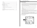
1.2 Communication Network
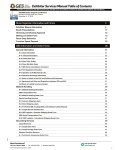
1.2.1 Units Connections
Max. 16
Max. 16
Port 1 (VRF)
AllonAlloff
SUN
AUTO
Max. 16
Max. 16
MON
TUE WED THU FRI SAT
CHLD
I LOCK
SET INNER UNIT
ROOM
COM
ALL
Port 2 (VRF)
TEMP
SHIELD MODE
ERROR
ON/OFF
9 10 11 12 13 14 15 16
CENTER
SUNM ON TUEW ED THUF RI SAT
24
68
10 12 14 16 18 20 22 24
Port 3 (VRF)
Mode
Mon
Tue
Wed
at
Sun
Thu
Port 4 (Duct Type)
Confirm/Cancel
Fan
FriS
On/Off
Max. 16
Shield
Timer/Time
Central
&HQWDO:LUHGe
Controller
Vired
Controller
Duct Type
Vired
Controller
Vired
Controller
Duct Type
Duct Type
Fig. 1.1 Unit Connection Diagram
1
&(175$/:,5('&21752/
Note: the FHQWUDOZLUHG controller can connect with a maximum of three sets of multi VRF units and multiple
duct type units, however, the total of the indoor units of all four ports may not exceed 16.
&(175$/:,5('&21752/
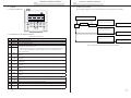
2.2 Introduction to Symbols on the LCD
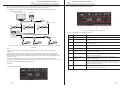
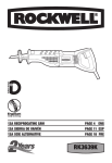
1.2.2 Integration of the &HQWUDO:LUHG Controller and Long-distance Monitoring System/
Centralized Controller.
Centralized controller
PC & Long-Distance Monitoring System
AllonAlloff
SUN
AUTO
MON
TUE WED THU FRI SAT
CHLD
I LOCK
SET INNER UNIT
ROOM
COM
TEMP
ON/OFF
9 10 11 12 13 14 15 16
Mode
ALL
SHIELD MODE
ERROR
o
CENTER
SUNM ON TUEW ED THUF RI SAT
24
68
10 12 14 16 18 20 22 24
Mon
Tue
Wed
FriS
at
Sun
Thu
Confirm/Cancel
Fan
On/Off
Shield
Timer/Time
Central
Max.16
Communication Module
Max.16
Communication Module
Max.16
Communication Module
Max.16
Fig. 2.2 Introduction to Symbols on the LCD
Port 1 (9RF)
AllonAlloff
SUN
AUTO
MON
TUE WED THU FRI SAT
CHLD
I LOCK
SET INNER UNIT
ROOM
COM
ALL
TEMP
SHIELD MODE
ERROR
Port 2 (9RF)
ON/OFF
9 10 11 12 13 14 15 16
Mode
CENTER
SUNM ON TUEW ED THUF RI SAT
Mon
24
68
10 12 14 16 18 20 22 24
Tue
Wed
at
Sun
Thu
Confirm/Cancel
Fan
FriS
On/Off
Shield
Timer/Time
Central
Table 2.1 Introduction to the Symbols on the LCD
Port 3 (9RF)
Port 4 (Duct Type)
Max.16
No.
&HQWUDO:LUHG Controller
(Max. 16 indoor units)
Vired Controller
Vired Controller
Duct Type
Duct Type
Vired Controller
Name
Fan speed
Displays the fan speed of the indoor unit: high, medium, low and auto.
2
Operating mode
Displays the operating mode of the indoor unit: auto, cool, dry, fan and
heat.
3
System clock
Displays the weekday and current time (hour and minute) based on a
24-hour time system.
4
Shield
Displays the shielded status, “ALL”, “TEMP”, “MODE” and “ON/
OFF”.
5
Weekly timer
Displays the timing period (unit: 0.5 hour) which will cycle each week.
6
Set temperature/Indoor
unit code
Displays the set temperature, indoor unit code (01-16), and the Celsius
or Fahrenheit scale symbols.
7
Control mode
Displays “CENTER” under the centralized control mode and no display
under the single control mode.
8
Ambient temperature/
Serial port
Displays the ambient temperature, serial port and the Celsius or
Fahrenheit scale symbols.
9
Indoor unit code/ on/off
status
The indoor unit codes are indicated by numbers which will be displayed
when the corresponding indoor unit is online. “ ” is the indoor unit on/
off status indicator. The unit is “On” when the indicator is lit; the unit is
“Off” when the indicator is not lit.
10
Error , Child lock
Displays the error codes when error(s) arise(s) and also “CHILD
LOCK” when this function is activated.
Duct Type
Fig.1.2 Connection of the &HQWUDO:LUHG Controller and the Long-distance Monitoring System/Centralized
Controller
Notes:
c. Only the multi VRF units can be integrated with the long-distance monitoring system/centralized
controller.
d If the shielding function has been set neither for the &HQWUDO:LUHG controller nor for the long-distance
monitoring system/the centralized controller, the &HQWUDO:LUHG controller will be fully compatible with the
long-distance monitoring system/the centralized controller. The &HQWUDO:LUHG’s control will be inferior to that
of the latter’s control.
e When the shielding function has been set for both the FHQWUDOZLUHG controller and the long-distance
monitoring system/the centralized controller, the &HQWUDO:LUHG controller can only be used to view the status of
the unit; its control function will be rendered ineffective.
2. LCD
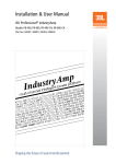
2.1 Outline of the LCD
Description
1
Fig. 2.1Outline of the LCD
2
3
&(175$/:,5('&21752/
3. Buttons
&(175$/:,5('&21752/
4. Control Flow Chart
3.1 Outline of Buttons
See the following figure for a view of the control flow chart of the smart zone controller.
AllonAlloff
SUN
AUTO
MON
TUE WED THU FRI SAT
CHLD
I LOCK
SET INNER UNIT
ROOM
COM
ALL
TEMP
No operations activated within 30 seconds
SHIELD MODE
ERROR
ON/OFF
9 10 11 12 13 14 15 16
CENTER
SUNM ON TUEW ED THUF RI SAT
24
68
10 12 14 16 18 20 22 24
Set the control command
Mode
Mon
Tue
Wed
Thu
(No operations activated within 2.5 seconds)
Center
Confirm/Cancel
FriS
Fan
at
Sun
Single
On/Off
Send out the control command
Centralized
Shield
Timer/Time
Central
Set the control command
(No operations activated within 2.5 seconds)
Send out the control command
3.1 Outline of Buttons
3.2 Introduction to the Button Functions
Table 3.1 Button Functions
No.
1
2
3
4
Name
Mode
Fan
On/Off
5
(
6
7
8
9
10
11
12
13
14
15
16
17
Mon
1/9
Tue
2/10
Wed
3/11
Thu
4/12
Fri
5/13
Sat
6/14
Sun
7/15
8/16
Timer/
Time
Central
Shield
All on/All
off
4
Description
Switches between modes.
Sets the fan speed: high, medium, low or auto.
Turns on/off the indoor unit.
1. Under the single/centralized control status: sets the operating temperature of the indoor
unit with max.30ºC and min. 16ºC;
2. Under the timing setting status: sets the timing period with max.24 hours and min.0 hours;
3. Under the clock setting status: sets the hour (max.:23, min.: 0) and minute (max.:59,
min.: 0) of the clock.
All on/All off
(No operations activated within 2.5 seconds)
Send out the control command
Fig. 4.1 Control Flow Chart of the &HQWUDO:LUHG Controller
Switches between unit 1 and unit 9; Under the timing or clock setting status, it indicates
Monday.
Switches between unit 2 and unit 10; Under the timing or clock setting status, it indicates
Tuesday.
Switches between unit 3 and unit 11; Under the timing or clock setting status, it indicates
Wednesday.
Switches between unit 4 and unit 12; Under the timing or clock setting status, it indicates
Thursday.
Switches between unit 5 and unit 13; Under the timing or clock setting status, it indicates
Friday.
Switches between unit 6 and unit 14; Under the timing or clock setting status, it indicates
Saturday.
Switches between unit 7 and unit 15; Under the timing or clock setting status, it indicates
Sunday.
Switches between unit 8 and unit 16.
Sets the timing or on/off time of the selected indoor unit as well as sets the clock of the system.
Switches between single and centralized control modes.
Deactivates some or all functions of a single or a group of the indoor unit(s).
Starts/stops all indoor units.
5
&(175$/:,5('&21752/
&(175$/:,5('&21752/
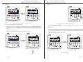
5. Operating Status View of the Indoor Unit and Control Mode
Fourteen seconds (thirty seconds for the duct type unit) after the control command is sent out, the set
parameters of the indoor unit will be displayed.
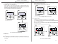
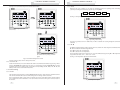
5.1 Operating Status View of the Indoor Unit
See Fig. 5.2 for temperature control instructions under single control:
It can be generally seen on the LCD that the minimum code of the online indoor unit flashes, with its
operating status, set temperature, and shield status etc., displayed. The minimum code can be replaced by
other indoor units by pressing the corresponding indoor unit code button (If the requested indoor unit is
offline, then the operation will be rendered null and void, displaying "NO".).
See Fig.5.1 for operating status viewing instructions of the indoor unit:
Allon Alloff
Allon Alloff
SUN
AUTO
SUN
AUTO
MON
MON
TUE WED THU FRI SAT
CHILD LOCK
SET INNER UNIT
ROOM
COM
ALL
TUE WED THU FRI SAT
TEMP
CENTER
Mode
SUN MON TUE WED THU FRI SAT
2
4
6
8
Tue
Wed
Fri
Sat
Sun
9 10 11 12 13 14 15 16
Thu
Confirm/Cancel
CENTER
SUN MON TUE WED THU FRI SAT
2
4
6
8
10 12 14 16 18 20 22 24
Mode
Confirm/Cancel
Fan
On/Off
TEMP
ON/OFF
10 12 14 16 18 20 22 24
Mon
ALL
SHIELD MODE
ERROR
ON/OFF
9 10 11 12 13 14 15 16
SET INNER UNIT
ROOM
COM
CHILD LOCK
SHIELD MODE
ERROR
10
Fan
Shield
Timer/Time
Central
Press the indoor unit code to select the
corresponding unit.
On/Off
10
( to adjust the temperature.
Fig. 5.2 Temperature Control under Single Control
For other settings, please refer to subsequent sections.
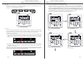
5.2.2 Centralized Control
The default status of the indoor unit is
the one with minimum code.
Press “2/10” to select unit 2.
Press Central to go to the centralized control mode. The LCD will display CENTER.
Set the operating status of the indoor unit and send out control commands, including On/Off, Mode, Fan,
will be sent out to all online indoor units.
Thirty seconds after the control command is sent out or if Central is pressed, CENTER will disappear
from the LCD and the unit will revert back to the single control mode with the set parameters of the
current indoor unit displayed.
See Fig.5.3 for instructions on entering the centralized control mode:
Allon Alloff
Allon Alloff
SUN
AUTO
SUN
AUTO
MON
MON
TUE WED THU FRI SAT
TUE WED THU FRI SAT
SET INNER UNIT
ROOM
CHILD LOCK COM
9 10 11 12 13 14 15 16
ALL
TEMP
SHIELD MODE
ERROR
SET INNER UNIT
ROOM
CHILD LOCK COM
CENTER
SUN MON TUE WED THU FRI SAT
2
4
6
8 10 12 14 16 18 20 22 24
9 10 11 12 13 14 15 16
ALL
TEMP
SHIELD MODE
ERROR
ON/OFF
ON/OFF
CENTER
SUN MON TUE WED THU FRI SAT
2
4
6
8 10 12 14 16 18 20 22 24
Press “2/10” again to select unit 10.
Fig.5.1 Operating Status View of the Indoor Unit
5.2 Control Mode
5.2.1 Single Control
Select the required indoor unit using the indoor unit code button. That particular code will flash on the LCD.
Set the operating status of the indoor unit and send out control commands, including On/Off, Mode, Fan,
will be sent out.
6
The default status of the indoor unit is
the one with minimum code.
Press “Central” to go to the centralized
control mode.
Fig. 5.3 Entering Centralized Control Mode
7
&(175$/:,5('&21752/
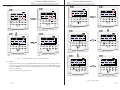
See Fig. 5.4 for centralized temperature control demonstration
&(175$/:,5('&21752/
5.3.2 Mode
When the unit is on, whether it is in single or centralized control, the operating mode will change
cyclically according to the following sequence by pressing Mode:
Cool
Dry
Fan
Heat
See Fig.5.5 for operating mode setting demonstration:
Al lon Al loff
SUN
AUTO
MON
TUE WED THU FRIS AT
SET INNER UNIT
ROOM
CHILD LOCK COM
ALL
ON/OFF
9 10 11 12 13 14 15 16
Press “Central” to go to the centralized
control mode.
TEMP
SHIELD MODE
ERROR
CENTER
SUNM ON TUEW ED THU FRI SAT
24
68
10 12 14 16 18 20 22 24
Tue
WedT
( to adjust the temperature.
Mod e
Mon
hu
Confirm/Cancel
Fr iS
Fa n
at
Su n
On/O ff
Shield
Timer/ Time
Centra l
Fig.5.5 Operating Mode Setting
If the duct type indoor unit is in Auto mode, it will be available for viewing through the FHQWUDOZLUHG
controller.
Quit this setting status automatically
30 seconds later or pressing “Control”
again..
In addition to timing and time setting, when the unit is on, whether it is under single or centralized control,
'#
The temperature will increase or decrease 1º*+
<==<
>
range under each mode: 16ºC ~ 30ºC /61ºC ~ 86ºC.
See Fig.5.6 for temperature adjustment demonstration:
Fig.5.4 Centralized Temperature Control
For other settings, please refer to subsequent sections.
5.2.3 All on/All off
AllonAlloff
Under all circumstances, the current indoor unit which is on/off will be turned off/on by pressing “All on/
All off”. CENTER will be displayed in the LCD. 2.5 seconds after pressing All on/All off, the control
!#$$%&
Shield), will be sent out to all online indoor units.
5.3 Control Setting
5.3.1 On/Off
The unit will be turned on/off by pressing On/Off whether the unit is under single or centralized control.
The control command will be sent out if the setting does not change within 2.5 seconds.
Note: Concerning the VRF system: in the case that an error occurs to the indoor unit or if mode conflicts
exist, whether the control command is on or off, the indoor unit of the VRF system will revert back to
the off state.
8
SUN
AUTO
MON
TUE WED THU FRI SAT
CHLD
I LOCK
SET INNER UNIT
ROOM
COM
ALL
TEMP
SHIELD MODE
ERROR
ON/OFF
9 10 11 12 13 14 15 16
CENTER
SUNM ON TUEW ED THUF RI SAT
24
68
10 12 14 16 18 20 22 24
Mode
Confirm/Cancel
Fan
On/Off
Fig.5.6 Temperature Adjustment
9
&(175$/:,5('&21752/
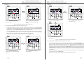
5.3.4 Fan
&(175$/:,5('&21752/
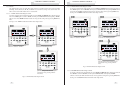
5.3.5.1 Setting the Weekly Timer under Single Control
When the unit is on, whether it is under single or centralized control, the fan speed will change cyclically
according to the following sequence by pressing “Fan”.
See Fig.5.7 for fan speed setting demonstration:
Auto
Low
M edium
High
In single control mode, it is possible to go to the weekly timer setting page by pressing Timer/Time. “*”
will flash (“*” indicates MON, TUE, WED, THU, FRI, SAT, or SUN). Press the weekday button to set the
weekday. After that, press Timer/Time@
J
finally press Confirm/Cancel to confirm this setting (without pressing Confirm/Cancel, the setting will
not be saved). Similarly, several time periods in one day can be set. After the setting is finished, please
press Timer/ Time to quit or wait for the timer to exit automatically 30 seconds later.
See Fig. 5.8 for weekly timer setting demonstration under single control:
AllonAlloff
SUN
AUTO
MON
TUE WED THU FRI SAT
CHLD
I LOCK
SET INNER UNIT
ROOM
COM
ALL
TEMP
SHIELD MODE
ERROR
ON/OFF
9 10 11 12 13 14 15 16
CENTER
SUNM ON TUEW ED THUF RI SAT
24
68
10 12 14 16 18 20 22 24
Mode
Confirm/Cancel
Fan
On/Off
Fig. 5.7 Fan Speed Control
5.3.5 Timer
The Timer, namely the weekly timer, has a one week cycle. The timer is enabled for on/off time settings
of the unit (measured in 0.5 hour units) for one or several days during a week with the option of several
time periods on the same day. The timer setting then preserves and repeats this setting weekly.
Introduction to the weekly timer:
a. Once the weekly timer is set, the unit will automatically be turned on/off as the set time starts/ends. For
instance, in the case that the current time is 9:00 Friday and the setting of the timer is as shown in the
figure below, the unit will turn on at 10:00, turn off at 10:30 and then turn on again at 12:30 and off at
13:30.
b. The weekly timer does not conflict with the manual on/off control, that is, the unit can be turned on/
off manually even if the weekly timer is set and the unit also can be turned on/off as according to the
setting of the weekly timer.
For instance, in the case that the weekly timer is set according to the figure below from 8:00 to 10:00 and
from 15:30 to 21:30, and the current time is 8:40 Friday and the unit is turned off manually, the unit will
be automatically turned on at 15:30 and later turned off at 21:30.
10
Under the single control mode, press
“Timer/Time” to go the timer setting
status.
Press the button of the weekday to select
the required weekday.
( to adjust the time period.
Press “Timer/Time” again to go to the
timer setting page.
11
&(175$/:,5('&21752/
&(175$/:,5('&21752/
(continued)
(continued)
Press “Confirm/Cancel” to confirm/
cancel the setting.
Quit the setting status automatically 30
seconds later or by pressing “Timer/
Time”.
Press “Timer/Time” to enter the setting
status.
Press “Confirm/Cancel” to cancel the
setting on this day.
Fig.5.8 Setting the Weekly Timer under Single Control
5.3.5.2 Cancelling the Weekly Timer under Single Control
In single control mode, it is possible to go to the weekly timing setting page by pressing Timer/Time.
“*” will flash (“*” indicates MON, TUE, WED, THU, FRI, SAT, or SUN). Press Confirm/ Cancel to
cancel the timing (i.e. the set timing period on this day). Subsequently, press the weekday button to enter
canceling status and press Confirm/Cancel to cancel the setting on this day.
After the cancellation, the unit will revert back to the weekly timer setting page. One may exit this page
by pressing Timer/Time twice (first press for entering the settings status and the second for quitting the
setting status) or by waiting for the unit to automatically exit 30 seconds later.
See Fig.5.9 for the weekly timer cancellation demonstration under single control:
Press “Timer/Time” again to quit this
setting status.
Fig.5.9 Cancelling the Weekly Timer under Single Control
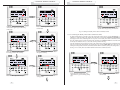
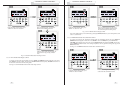
5.3.5.3 Setting the Weekly Timer under Centralized Control
Under the single control status, press
“Timer/Time” to go to the timer setting
page.
12
Press rhe button of the weekday to select
the required day.
In single control, it is possible to go to the weekly timing setting page by pressing Timer/Time. “*” will
flash (“*” indicates MON, TUE, WED, THU, FRI, SAT, or SUN). Press Central and CENTER will be
displayed on the LCD, indicating that one may now set the weekly timer under the centralized control.
Press the weekly day button to choose the desired day, press Timer/Time@
J
<
Confirm/Cancel to end this setting (without pressing
Confirm/Cancel, the setting will not be saved). Following the above procedure indicates that this day is
timed for all indoor units. In addition, several time periods can be set on one day using the same method
as stated above.
After setting completion, one may quit the timer setting status by waiting for it to exit automatically 30
seconds later or by pressing Timer/ Time.
See Fig. 5.10 for weekly timer setting demonstration under centralized control.
13
&(175$/:,5('&21752/
&(175$/:,5('&21752/
Al lon Al loff
SUN
AUTO
MON
TUE WED THU FRIS AT
CHILD LOCK
SET
ET INNER UNIT
ROOM S
COM
ALL
TEMP
SHIELD MODE
ERROR
ON/OFF
9 10 11 12 13 14 15 16
Mod e
CENTER
SUNM ON TUEW
WED
ED THUF RI SAT
68
10 12 14 16 18 20 22 24
Mo n
Tue
WedT
Fr iS
at
24
hu
Confirm/Cance l
Fa n
Sun
On/O ff
Shiel d
Timer/ Time
Under the single control status,press
“Timer/Time” again to go to the timing
setting page.
Press “Central” to go to the centalized
control mode
Centra l
Quit this setting status automatically 30
seconds later or by pressing “Timer/Time”.
Fig. 5.10 Setting the Weekly Timer under Centralized Control
5.3.5.4 Cancelling the Weekly Timer under Centralized Control
In single control mode it is possible to go to the weekly timer setting page by pressing Timer/Time. “*”
will flash (“*” indicates MON, TUE, WED, THU, FRI, SAT, or SUN). Press Central and CENTER will
be displayed on the LCD, indicating that one may now set the weekly timer under centralized control.
Press the weekday button to choose the desired day and then press Confirm/ Cancel to cancel the setting
on this day for all indoor units ( i.e. cancel the set time period on this day).
After the cancellation, the unit will revert back to the weekly timer setting page under centralized control.
One may exit this page automatically 30 seconds later or by pressing Timer/Time twice (first press for
entering the settings status under the centralized control and the second for quitting this setting status).
See Fig.5.11 for weekly timer cancellation demonstration under centralized control:
Press “Timer/Time” again to go to set
the timing period on this weekday.
Press the button of the weekday to select
the required weekday.
Allon Alloff
Allon Alloff
SUN
AUTO
MON
SUN
AUTO
MON
TUE WED THU FRI SAT
SET INNER UNIT
ROOM
CHILD LOCK COM
9 10 11 12 13 14 15 16
Mode
TUE WED THU FRI SAT
ALL
TEMP
ON/OFF
CENTER
2
4
6
8 10 12 14 16 18 20 22 24
9 10 11 12 13 14 15 16
Mon
Tue
Wed
Fri
Sat
Sun
Thu
Mode
ALL
TEMP
SHIELD MODE
ERROR
SUN MON TUE WED THU FRI SAT
SET INNER UNIT
ROOM
CHILD LOCK COM
SHIELD MODE
ERROR
ON/OFF
CENTER
SUN MON TUE WED THU FRI SAT
6
8 10 12 14 16 18 20 22 24
Mon
Tue
Wed
Fri
Sat
Sun
2
4
Thu
Confirm/Cancel
Confirm/Cancel
Fan
Fan
On/Off
Shield
Timer/Time
( to adjust the time period.
14
Press “Confirm/Cancel” to cancel the
setting period.
Central
Under the single control status, press
“Timer/Time” to go to the timing setting
page.
On/Off
Shield
Timer/Time
Central
Press “Central” to go to the centralized
control mode.
15
&(175$/:,5('&21752/
&(175$/:,5('&21752/
(continued)
Allon Alloff
TUE WED THU FRI SAT
SET INNER UNIT
ALL
9 10 11 12 13 14 15 16
TEMP
ON/OFF
CENTER
9 10 11 12 13 14 15 16
SUN MON TUE WED THU FRI SAT
2
4
6
ALL
TEMP
TUE WED THU FRI SAT
TEMP
CHILD LOCK
SHIELD MODE
9 10 11 12 13 14 15 16
SUN MON TUE WED THU FRI SAT
CENTER
2
4
6
8 10 12 14 16 18 20 22 24
Tue
Wed
9 10 11 12 13 14 15 16
Wed
CENTER
2
6
8 10 12 14 16 18 20 22 24
Mon
Tue
Wed
Fri
Sat
Sun
4
SUN MON TUE WED THU FRI SAT
2
4
6
8 10 12 14 16 18 20 22 24
Mode
8 10 12 14 16 18 20 22 24
Tue
TEMP
SUN MON TUE WED THU FRI SAT
ON/OFF
CENTER
Mode
Mon
ALL
SHIELD MODE
ON/OFF
Mon
Thu
Mode
Confirm/Cancel
Mode
SET INNER UNIT
ROOM
COM
ERROR
ON/OFF
ALL
SHIELD MODE
ERROR
SHIELD MODE
ERROR
SET INNER UNIT
ROOM
CHILD LOCK COM
SET INNER UNIT
ROOM
COM
ERROR
MON
TUE WED THU FRI SAT
ROOM
CHILD LOCK COM
CHILD LOCK
SUN
AUTO
MON
MON
TUE WED THU FRI SAT
Allon Alloff
SUN
SUN
AUTO
MON
AllonAlloff
AUTO
Allon Alloff
SUN
AUTO
Mon
Tue
Wed
Fri
Sat
Sun
Fri
Fan
Thu
Thu
Confirm/Cancel
Sat
Sun
Fan
Thu
Confirm/Cancel
Confirm/Cancel
Fan
Fri
Fan
Sat
On/Off
On/Off
On/Off
On/Off
Central
Shield
Timer/Time
Central
Shield
Timer/Time
Shield
Timer/Time
Shield
Timer/Time
Sun
Central
Central
Press “Timer/Time” for five seconds to go
to the clock setting status.
Press “Confirm/Cancel” to cancel the set
time period.
Press the button of the week day to
select the expected week day..
Press the button of the weekday to select
the required weekday.
Allon Alloff
Allon Alloff
SUN
AUTO
SUN
AUTO
MON
MON
TUE WED THU FRI SAT
TUE WED THU FRI SAT
Allon Alloff
AllonAlloff
CHILD LOCK
SET INNER UNIT
ROOM
COM
ALL
AUTO
MON
TUE WED THU FRI SAT
SET INNER UNIT
ROOM
CHILD LOCK COM
9 10 11 12 13 14 15 16
ALL
SUN MON TUE WED THU FRI SAT
2
4
6
8 10 12 14 16 18 20 22 24
9 10 11 12 13 14 15 16
9 10 11 12 13 14 15 16
ALL
CENTER
SUN MON TUE WED THU FRI SAT
2
4
6
8 10 12 14 16 18 20 22 24
Tue
Wed
Tue
Wed
Fri
Sat
Sun
Thu
Confirm/Cancel
Fan
Mode
9 10 11 12 13 14 15 16
On/Off
Shield
Timer/Time
Central
CENTER
SUN MON TUE WED THU FRI SAT
2
4
6
Mode
8 10 12 14 16 18 20 22 24
Mon
Mode
Thu
6
8 10 12 14 16 18 20 22 24
Mon
Tue
Wed
Fri
Sat
Sun
2
4
Mon
Tue
Wed
Fri
Sat
Sun
Fri
Sat
Fan
Sun
Thu
On/Off
On/Off
Thu
Confirm/Cancel
On/Off
Shield
Timer/Time
Shield
Timer/Time
Central
Central
Shield
Timer/Time
Central
Press “Timer/Time” again to go to minute
setting status.
Press “Timer/Time” to enter the setting
status.
CENTER
TEMP
Confirm/Cancel
Fan
TEMP
SUN MON TUE WED THU FRI SAT
ON/OFF
Fan
Mon
ALL
SHIELD MODE
ON/OFF
Confirm/Cancel
Mode
SET INNER UNIT
ROOM
COM
ERROR
SHIELD MODE
ERROR
ON/OFF
CENTER
TUE WED THU FRI SAT
SET INNER UNIT
ROOM
CHILD LOCK COM
TEMP
SHIELD MODE
ERROR
CHILD LOCK
ON/OFF
SUN
AUTO
MON
TEMP
SHIELD MODE
ERROR
SUN
(to set the hour.
Press “Timer/Time” to quit the setting
status.
SUN
AUTO
5.3.6 Time
CHILD LOCK
SET INNER UNIT
ROOM
COM
9 10 11 12 13 14 15 16
Mode
MON
TUE WED THU FRI SAT
TUE WED THU FRI SAT
ALL
TEMP
CHILD LOCK
SUN MON TUE WED THU FRI SAT
Mon
2
4
6
8 10 12 14 16 18 20 22 24
Tue
Wed
9 10 11 12 13 14 15 16
Mode
Thu
ALL
TEMP
SHIELD MODE
ON/OFF
CENTER
SUN MON TUE WED THU FRI SAT
6
8 10 12 14 16 18 20 22 24
Mon
Tue
Wed
Fri
Sat
Sun
2
4
Thu
Confirm/Cancel
Confirm/Cancel
Fan
SET INNER UNIT
ROOM
COM
ERROR
ON/OFF
CENTER
SUN
AUTO
MON
SHIELD MODE
ERROR
Enter the clock setting status by pressing Timer/Time for fifteen seconds. Press the weekday button to
'
X<
Timer/Time and
set the day and
'
Timer/Time or wait five seconds and the system will
exit the time setting status.
See Fig. 5.12 for clock setting demonstration.
Allon Alloff
Allon Alloff
Fig.5.11 Cancelling the Weekly Timer under Centralized Control
Fri
Sat
Sun
On/Off
Fan
On/Off
Shield
Timer/Time
( to adjust the minute.
Shield
Timer/Time
Central
Central
Quit the setting status automatically 15
seconds later or by pressing “Timer/Time”.
Fig. 5.12 Clock Setting
16
17
&(175$/:,5('&21752/
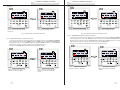
5.3.7 Shield
&(175$/:,5('&21752/
5.3.7.2 MODE Shield under Single Control
The shield function can be set under either single control or centralized control. The control command
!#$$%&Y
will be sent out to all online indoor units 2.5 seconds later.
5.3.7.1 “TEMP” Shield under Single Control
To activate or deactivate the mode shield: first press Shield and SHIELD will be displayed on the LCD.
Press Shield again to switch to MODE, and then press Confirm/Cancel. Subsequently, MODE will turn
on and off, but ON/OFF will flash instead. One may quit this setting status by pressing Shield twice.
See Fig.5.14 for MODE shield demonstration under single control:
To activate or deactivate the temperature shield: first press Shield and SHIELD will be displayed on the
LCD. Press Shield again to switch to TEMP, and then press Confirm/Cancel. Subsequently, “TEMP”
will turn on or off but MODE will flash instead. One may quit this setting status by pressing Shield three
times.
See Fig.5.13 for “TEMP” shield demonstration under single control
9 10 11 12 13 14 15 16
Mode
SUN
AUTO
9 10 11 12 13 14 15 16
Mode
Mon
2
4
6
8 10 12 14 16 18 20 22 24
Tue
Wed
9 10 11 12 13 14 15 16
Sat
On/Off
Thu
Mode
Fan
Sun
Shield
Timer/Time
CENTER
Mon
2
4
6
8 10 12 14 16 18 20 22 24
Tue
Wed
9 10 11 12 13 14 15 16
Thu
TEMP
ON/OFF
SUN MON TUE WED THU FRI SAT
CENTER
Mode
SUN MON TUE WED THU FRI SAT
2
6
8 10 12 14 16 18 20 22 24
Mon
Tue
Wed
Fri
Sat
Sun
4
Thu
Confirm/Cancel
Fri
Sat
On/Off
ON/OFF
CENTER
Fan
Sun
Shield
Timer/Time
On/Off
Shield
Timer/Time
Central
Central
SUN MON TUE WED THU FRI SAT
6
8 10 12 14 16 18 20 22 24
Mon
Tue
Wed
Fri
Sat
Sun
2
4
Under the single control status, press
“Shield ” to switch to “MODE” .
Thu
Confirm/Cancel
Fri
ALL
SHIELD MODE
ERROR
TEMP
SHIELD MODE
ERROR
SUN MON TUE WED THU FRI SAT
Confirm/Cancel
Fan
ALL
ON/OFF
CENTER
TUE WED THU FRI SAT
SET INNER UNIT
ROOM
CHILD LOCK COM
TEMP
ON/OFF
TUE WED THU FRI SAT
SET INNER UNIT
ROOM
CHILD LOCK COM
TEMP
SHIELD MODE
ERROR
Fan
MON
TUE WED THU FRI SAT
ALL
ALL
SHIELD MODE
Confirm/Cancel
SUN
AUTO
MON
SET INNER UNIT
ROOM
CHILD LOCK COM
MON
TUE WED THU FRI SAT
SET INNER UNIT
ERROR
AllonAlloff
SUN
AUTO
MON
ROOM
CHILD LOCK COM
AllonAlloff
Allon Alloff
Allon Alloff
SUN
AUTO
On/Off
Press “Confirm/Cancel” to activate or
deactivate the shielding function.
Shield
Timer/Time
Central
Central
Allon Alloff
Under the single control status, press
“Shield” to switch to “TEMP”.
SUN
AUTO
Press “Confirm/Cancel” to activate or
deactivate the shielding function.
MON
TUE WED THU FRI SAT
SET INNER UNIT
ROOM
CHILD LOCK COM
9 10 11 12 13 14 15 16
Mode
ALL
TEMP
SHIELD MODE
ERROR
ON/OFF
CENTER
SUN MON TUE WED THU FRI SAT
6
8 10 12 14 16 18 20 22 24
Mon
Tue
Wed
Fri
Sat
Sun
2
4
Thu
Confirm/Cancel
Allon Alloff
Fan
SUN
AUTO
MON
TUE WED THU FRI SAT
SET INNER UNIT
ROOM
CHILD LOCK COM
9 10 11 12 13 14 15 16
Mode
ALL
On/Off
TEMP
CENTER
6
8 10 12 14 16 18 20 22 24
Mon
Tue
Wed
Fri
Sat
Sun
2
4
On/Off
Quit this setting mode automatically 30
seconds later or by pressing “Shield”
twice.
Thu
Shield
Timer/Time
Central
Quit this setting mode automatically 30
seconds later or by pressing “Shield”
three times.
Fig.5.13 TEMP Shield under Single Control
18
Central
ON/OFF
SUN MON TUE WED THU FRI SAT
Confirm/Cancel
Fan
Shield
Timer/Time
SHIELD MODE
ERROR
Fig. 5.14 MODE Shield under Single Control
5.3.7.3 ON/OFF Shield under Single Control
To activate or deactivate the on/off shield: first press Shield and SHIELD will be displayed on the LCD.
Press Shield to switch to ON/OFF, and then press Confirm/Cancel. Subsequently, ON/OFF
will turn on and off, but ALL will flash instead. One may quit this setting state by pressing Shield twice.
See Fig.5.15 for ON/OFF shield demonstration under single control.
19
&(175$/:,5('&21752/
&(175$/:,5('&21752/
Allon Alloff
Allon Alloff
SUN
AUTO
SUN
AUTO
MON
MON
TUE WED THU FRI SAT
TUE WED THU FRI SAT
SET INNER UNIT
ROOM
CHILD LOCK COM
9 10 11 12 13 14 15 16
Mode
ALL
CENTER
SUN MON TUE WED THU FRI SAT
Mon
2
4
6
8 10 12 14 16 18 20 22 24
Tue
Wed
9 10 11 12 13 14 15 16
Thu
Fri
Sat
Fan
Sun
Shield
Timer/Time
Press “Confirm/Cancel” to activate or
deactivate the shielding function.
Mode
TEMP
ON/OFF
CENTER
SUN MON TUE WED THU FRI SAT
6
8 10 12 14 16 18 20 22 24
Mon
Tue
Wed
Fri
Sat
Sun
2
4
Thu
Confirm/Cancel
On/Off
Under the single control status, press
“Shield” to switch to “ON/OFF”.
ALL
SHIELD MODE
ERROR
ON/OFF
Confirm/Cancel
Fan
SET INNER UNIT
ROOM
CHILD LOCK COM
TEMP
SHIELD MODE
ERROR
Central
Under the single control status, press
“Shield ” to switch to “All”.
On/Off
Shield
Timer/Time
Central
Press “Confirm/Cancel” to activate or
deactivate the shielding function and at
the same time quit this setting status.
Fig. 5.16 ALL Shield under the Single Control
Note: if the shield setting is not confirmed by pressing Confirm/Cancel, the system will quit this setting
status 15 seconds later.
5.3.7.5 TEMP Shield under the Centralized Control
To activate or deactivate the temperature shield under the centralized control: first press Shield and
SHIELD will be displayed on the LCD. Press Shield to switch to TEMP, then press Central and
CENTER will be displayed on the LCD. Press Confirm/Cancel. Subsequently, TEMP will turn on or
off but MODE will flash instead. After setting completion, one may quit this setting status by pressing
Shield three times.
See Fig.5.17 for TEMP shield demonstration under centralized control:
Quit this setting mode automatically 30
seconds later or by pressing “Shield”
once.
Fig. 5.15 ON/OFF Shield under the Singe Control
5.3.7.4 ALL Shield under Single Control
To activate or deactivate the all shield: first press Shield and SHIELD will be displayed on the LCD.
Press Shield to switch to ALL, and then press Confirm/Cancel. Subsequently, ON/OFF will turn on or
off and at the same time exit this setting status.
See Fig.5.16 for ALL Shield demonstration under single control:
Under the single control status, press
“Shield” to switch “TEMP”
20
Press”Cancel” to go to the shielding setting
status under the centralized control.
21
&(175$/:,5('&21752/
(continued)
(continued)
Allon Alloff
SET INNER UNIT
9 10 11 12 13 14 15 16
Mode
ALL
CENTER
Mon
2
4
6
8 10 12 14 16 18 20 22 24
Tue
Wed
ALL
9 10 11 12 13 14 15 16
Thu
TEMP
CENTER
SUN MON TUE WED THU FRI SAT
2
4
6
8 10 12 14 16 18 20 22 24
Tue
Wed
9 10 11 12 13 14 15 16
CENTER
Mon
SUN MON TUE WED THU FRI SAT
6
8 10 12 14 16 18 20 22 24
Mon
Tue
Wed
Fri
Sat
Sun
2
4
Thu
9 10 11 12 13 14 15 16
Thu
Sat
On/Off
Sun
Fan
Shield
Timer/Time
Central
Fri
Fan
Sun
CENTER
Mode
Fan
On/Off
On/Off
Shield
Shield
Timer/Time
Quit this setting status automatically 30
seconds later or by pressing “Shield”
three times.
Sat
Timer/Time
Central
6
8 10 12 14 16 18 20 22 24
Mon
Tue
Wed
Fri
Sat
Sun
2
4
Thu
On/Off
Shield
Timer/Time
Central
Press “ Confirm/Cancel ” to activate /
deactivate the shielding function.
TEMP
ON/OFF
SUN MON TUE WED THU FRI SAT
Confirm/Cancel
Confirm/Cancel
Fri
ALL
SHIELD MODE
ERROR
ON/OFF
Confirm/Cancel
Confirm/Cancel
SET INNER UNIT
ROOM
CHILD LOCK COM
SHIELD MODE
ERROR
Mode
Mode
ALL
TUE WED THU FRI SAT
ON/OFF
SET INNER UNIT
ROOM
CHILD LOCK COM
TEMP
SHIELD MODE
ERROR
SUN MON TUE WED THU FRI SAT
SET INNER UNIT
ROOM
CHILD LOCK COM
ON/OFF
MON
TUE WED THU FRI SAT
TUE WED THU FRI SAT
TEMP
SHIELD MODE
ERROR
SUN
AUTO
MON
MON
TUE WED THU FRI SAT
Allon Alloff
SUN
AUTO
SUN
AUTO
MON
ROOM
CHILD LOCK COM
Allon Alloff
AllonAlloff
SUN
AUTO
Fan
&(175$/:,5('&21752/
Quit this setting status automatically 30
seconds later or by pressing “Shield” twice.
Central
Press “Confirm/Cancel” to activate /
deactivate the shielding function.
Fig.5.18 MODE Shield under the Centralized Control
Fig.5.17 TEMP Shield under Centralized Control
5.3.7.7 ON/OFF Shield under Centralized Control
5.3.7.6 MODE Shield under Centralized Control
To activate or deactivate the mode shield under the centralized control: first press Shield and SHIELD
will be displayed on the LCD. Press Shield to switch to MODE, and press Central and CENTER will
be displayed on the LCD. Press Confirm/Cancel. Subsequently, MODE will turn on or off but ON/OFF
will flash instead. One may quit this setting status by pressing Shield twice.
See Fig.5.18 for MODE shield demonstration under centralized control:
To activate or deactivate the on/off shield under the centralized control: first press Shield and SHIELD
will be displayed on the LCD. Press Shield to switch to ON/OFF, press Central and CENTER will be
displayed on the LCD and then press Confirm/Cancel. Subsequently, ON/OFF will turn on or off but
ALL will flash instead. One may quit this setting status by pressing Shield once.
See Fig.5.19 for “ON/OFF” shield demonstration under centralized control:
Allon Alloff
Allon Alloff
SUN
AUTO
SUN
AUTO
MON
MON
TUE WED THU FRI SAT
SET INNER UNIT
ROOM
CHILD LOCK COM
9 10 11 12 13 14 15 16
Under the single control status, press
“Shield” to switch to “MODE”.
22
Press “Central” to go to the shielding
setting status under the centralized
control.
ALL
TEMP
SHIELD MODE
ERROR
ON/OFF
CENTER
SUN MON TUE WED THU FRI SAT
2
4
6
8 10 12 14 16 18 20 22 24
Under the single control status, press
“Shield” to switch to “ON/OFF”.
TUE WED THU FRI SAT
SET INNER UNIT
ROOM
CHILD LOCK COM
9 10 11 12 13 14 15 16
ALL
TEMP
SHIELD MODE
ERROR
ON/OFF
CENTER
SUN MON TUE WED THU FRI SAT
2
4
6
8 10 12 14 16 18 20 22 24
Press “Central” to go to the shielding
setting status under the centralized
control.
23
&(175$/:,5('&21752/
(continued)
&(175$/:,5('&21752/
(continued)
onAllloff
AllonA
AllonA
onAllloff
Press “Confirm/Cancel” to activate/
deactivate the shielding function and
simultaneously exit the setting status.
Quit this setting status automatically 30
Press “Confirm/Cancel” to activate /
seconds later or by pressing “Shield”
deactivate the shielding function.
once.
Fig.5.19 “ON/OFF” Shield under Centralized Control
5.3.7.8 “ALL” Shield under Centralized Control
To activate or deactivate the all shield for the centralized control: first press Shield and SHIELD will
be displayed on the LCD. Press Shield to switch to ALL, press Central and CENTER will be displayed
on the LCD and then press Confirm/Cancel. Subsequently, ALL will turn on or off and the unit will
exit the
setting status at the same time.
See Fig.5.20 for ALL shield demonstration under centralized control:
Under the single control status, press
“Shield ” to switch to “ALL”.
Press “Central” to go to the shielding
setting status under centralized control.
Fig.5.20 ALL Shield under Centralized Control
Note: if the shield setting is not confirmed by pressing Confirm/Cancel, the system will quit this setting
status automatically 30 seconds later.
5.3.8 Child Lock
Z
<+[<
<
for five seconds. CHILD LOCK will be displayed on the LCD and no button pressing except for the
'
>+<
procedure stated above.
See Fig.5.21 for child clock setting demonstration:
\
(simultanelusly for five seconds.
Go to the locking status with “CHILD
LOCK” displayed on the LCD.
Fig.5.21 Child Lock
24
25
&(175$/:,5('&21752/
&(175$/:,5('&21752/
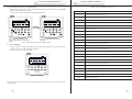
5.3.9 Switching between Celsius and Fahrenheit
Table 6.1 Errors for Multi VRF Indoor Units
When the current indoor unit is off, one may switch between Celsius and Fahrenheit by pressing Mode
<
+
See Fig.5.22 for Celsius and Fahrenheit switching demonstration:
Switch over the Celsius scale and the
Under the off state of the unit, press
Farenheit.
“Mode” and ( simultaneously for five
seconds.
Fig. 5.22 Switching between Celsius and Fahrenheit
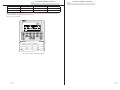
6. Error Display
When an error arises during system operation, error codes will be displayed at the location where the
ambient temperature is usually displayed on the LCD.
See Fig.6.1 for a view of the error display:
Al lon Al loff
SUN
AUTO
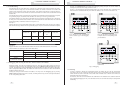
Code
Description
E1
High pressure protection of the compressor
E2
Anti-freezing protection of the indoor unit
E3
Low pressure protection of the compressor
E4
Discharge temperature protection of the compressor
E5
Over-current protection, overload protection of compressor, drive error
E6
Communication error
E7
Mode conflict
E9
Water overflow protection
EH
E-heater protection
F0
Ambient temperature sensor error of the indoor unit
F1
Error of coil pipe inlet sensor of the indoor unit
F2
Error of coil pipe intermediate sensor of the indoor unit
F3
Error of coil pipe outlet sensor of the indoor unit
F4
Ambient temperature sensor error of the outdoor unit
F5
Error of coil pipe inlet sensor of the outdoor unit
F6
Error of coil pipe intermediate sensor of the outdoor unit
F7
Error of coil pipe outlet sensor of the outdoor unit
F8
Error of discharge temperature sensor 1 (fixed)
F9
Error of discharge temperature sensor 2 (digital)
FA
Error of oil temperature sensor 1 (fixed)
Fb
Error of oil temperature sensor 2 (digital)
Fc
High pressure sensor error
Fd
Low pressure sensor error
MON
TUE WED THU FRIS AT
SET INNER UNIT
ROOM
CHILD LOCK COM
TEMP
ON/OFF
9 10 11 12 13 14 15 16
Mod e
ALL
SHIELD MODE
ERROR
CENTER
SUNM ON TUEW ED THU FRIS AT
24
68
10 12 14 16 18 20 22 24
Mo n
Tue
Wed
Fri
Sat
Su n
Thu
Confirm/Cance l
Fa n
On/Of f
Shield
Timer/ Time
Centra l
Fig. 6.1 Error Display
See Table 6.1 for a list of errors of the multi VRF indoor units and see Table 6.2 for a list of errors of the duct
type indoor units.
26
27
&(175$/:,5('&21752/
Table 6.1 Errors for Multi VRF Indoor Units
Code
Description
E0
Water pump error
E1
High pressure protection of the compressor
E2
Anti-freezing protection of the indoor unit
E3
Low pressure protection of the compressor
E4
High discharge temperature protection of the compressor
E5
Overload protection of the compressor
E6
Communication error
E8
Indoor unit fan protection
E9
Water overflow protection
F0
Indoor ambient temperature sensor error at the return air inlet.
F1
Evaporator temperature sensor error
F2
Condenser temperature sensor error
F3
Indoor ambient temperature sensor error
F4
Discharge temperature sensor error
F5
Ambient temperature sensor error at the display
EH
Auxiliary electrical heater error
FF
Sub-room switch opened
C5
Jumper cap error
C1
Arc control
C2
Electrical leakage protection
&(175$/:,5('&21752/
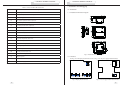
7. Installation and Debugging
7.1 Installation
7. 1.1 Installation Dimension Diagram
Fig.7.1 Installation Dimension Diagram
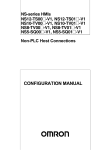
7.1.2 Interfaces
AC-L
See Fig.7.2 for the display board interfaces and see Fig.7.3 for the power supply module interfaces.
CN1
AC-N
GND
+9.8V
CN1
CN5
CN4 CN3
COM1
COM2
CN2
COM3
COM4
Fig.7.2 Display Board Interfaces
28
9.8V GND
CN4
Fig.7.3 Power Supply Module Board Interfaces
29
&(175$/:,5('&21752/
&(175$/:,5('&21752/
a. Power Supply Interface
c The power supply module board CN1 interface is for the external power cord connection board. The AC-N
terminal is for the neutral line, the AC-L terminal is for the live line and the middle terminal remains open.
d
The power supply module board CN4 interface, which is for the power supply of the display board, is
connected with the display board CN1 interface using the two-core wire provided by XQLW.
b. Communication Interface
The CN2, CN3, CN4 and CN5 interfaces of the display board are for communication. CN2, namely
COM4, is for the duct type unit (2-pin) communication; CN5, CN4, CN3, namely COM1, COM2, COM3
respectively, are for the multi VRF system (3-pin) communication.
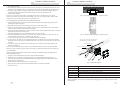
Fig.7.4 Concealed Cable Installation 1 (right-left wiring)
7.1.3 Preparation and Connection of the Communication Line
a. The communication line between the centralized controller and the unit should be prepared by the user
according to the particular project.
b. Preparation and connection of the communication line for the multi VRF system
c. One three-core communication line is needed to connect one set of a multi VRF system to one interface
(COM1, COM2 or COM3) of the FHQWUDOZLUHG controller.
d. One end of the communication line is connected with the FHQWUDOZLUHG controller and the other is connected
with the three-pin socket of the indoor unit.
c. Preparation and connection of the communication line for the duct type unit
c . The communication line for the duct type unit is the two-core line provided by XQLW (one end is the twocore head and the other end is the crystal head, code: 40113325).
d . If N sets of duct type units exist, then N+1 communication lines are required.
e. Connect the two-core heads of one communication line to the COM4 port of the FHQWUDOZLUHG controller
and connect the two-core heads of N communication lines to the two-pin socket of the duct type unit wired
controller.
f . The user can prepare the extension line and connect the wires inside the crystal head according to his
particular requirements.
Note: one set of a Multi VRF system consists of one multi VRF outdoor unit and one or more multi VRF
indoor units. One set of duct type units consists of one duct type outdoor unit and one duct type indoor unit.
Fig.7.5 Concealed Cable Installation 2 (up-down wiring
Note: the power cord must be separeted from the
communication line to avoid any interference
Hole for the power cord
Hole for the communication line
7.1.4 Installation
One may proceed with installation of the units after selecting an installation location and adhering to the
following installation steps:
a. Verify the set location intended for the FHQWUDOZLUHG controller installation.
b. Embed the power supply box (2) as displayed in Fig.7.6 for the installation of the bottom case (3).
c. Connect the power cord and the communication line of the display board and then thread both of them
through the power supply box (2).
d. Attach the bottom case onto the power box (2) using screws.
e. Tidy up the power cord and the communication line inside the FHQWUDOZLUHG controller.
f. Close the cover (5).
Fig. 7.6 Installation Diagram
Serial No.
Description
1
Wall
2
Power Supply Box (86)
3
Bottom Base(including power supply module board)
4
Screw
5
Top Cover(including the display board)
After the installation, it is necessary to run through the debugging process in order to guarantee normal
communication.
30
31
&(175$/:,5('&21752/
7.2 Unit Matching
Provided that only the multi VRF unit is required for a particular project and the outdoor unit with a
connection board is being used, one FHQWUDOZLUHG controller can control a maximum of 16 indoor units
matched with a maximum of three connection boards. If the outdoor unit without a connection board is
being used, one FHQWUDOZLUHG controller can control a maximum of 16 indoor units and maximum of three
outdoor units.
Provided that only the duct type indoor unit (one outdoor unit is matched with one indoor unit) is required
for a particular project, one FHQWUDOZLUHG controller can control up to 16 duct type indoor units.
Provided that both duct type units and the multi VRF units are required for a particular project, a maximum
of three ports of the FHQWUDOZLUHG controller can be connected with the multi VRF units. The maximum
permissible quantity of all indoor units at the four ports is 16.
Example 1:
Suppose that there are three multi VRF outdoor units, 10 multi VRF indoor units, five duct type outdoor
units and five duct type indoor units for a particular project. Only one FHQWUDOZLUHG controller is required
Project Demand
Quantity(set)
Multi VRF System
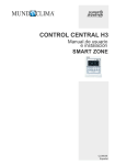
Pressing on Confirm/Cancel will confirm this debugging setting and open the current indoor unit
viewing state; otherwise this setting will not be saved.
See Fig.7.7 for the debugging operation demonstration. Fig.7 shows the indoor unit 1 and indoor unit 2
both of which are connected with the port COM2. The address of one is 01 and of the other is 04.,
Duct Type Unit
Multi VRF
Outdoor Unit
Connection
Board
Multi
VRF
&MV-R300W
/
/
3
0
10
Quantity
(&HQWUDOZLUHG controller)
&(175$/:,5('&21752/
Series E Duct
Type Outdoor
Uni
<8'
Duct Type
Indoor Unit
'%'
5
Press “Mode” and "Thu" simultaneously
for five seconds to go to the debugging
page.
Press the code button of the indoor unit
to inquire about its corresponding serial
port and address.
5
1.
Example 2:
Suppose that there are two &095: outdoor units and 32 multi VRF indoor units. TwoFHQWUDO
ZLUHG controllers are required, as shown in the table below:
Project Demand
Quantity (set)
Quantity
Multi VRF System
Outdoor Unit
Connection Board
Indoor Unit
&MV-R300W
/
/
4
32
2
2
(&HQWUDO:LUHG controller)
7.3 Debugging and Viewing the Port No. and the Indoor Unit Address
Debugging setting: when the unit is initially powered up, when the project setting changes or when the
serial port is replaced, one may enter debugging mode by pressing Mode and Thu simultaneously for five
seconds. The debugging setting automatically checks and distributes the indoor unit address. Debugging
will be completed 10 minutes later. The indoor unit which receives the address is under control and the
unaddressed indoor unit is not.
Viewing the serial port and the indoor unit address: One may access the debugging page by pressing
Mode and Thu simultaneously for five seconds, at which point one may view the serial port and address
of the corresponding indoor unit.
32
Press “Confirm/Cancel” to mahe a
confirmation.
Fig.7.7 Debugging
7.4 Labeling
A label is provided to identify the relationship between the indoor unit No. and the corresponding
room name. The user can write down the indoor unit No. and its corresponding room name on the label
which will then be stuck to the inside of the FHQWUDOZLUHG controller cover so that the user will have clear
information about the control object.
For instance, when the user has installed the air conditioners in the children's room, bedroom and living
room, following debugging one may view the indoor unit No. of each room and clarify its corresponding
relationship.
33
&(175$/:,5('&21752/
Living Room
Bedroom
Child Room
Room Name
Port 1 ,Indoor Unit 06
Port 1, Indoor Unit 05
Port 1,Indoor Unit 04
Indoor Unit Address
3
2
1
.Indoor Unit No
&(175$/:,5('&21752/
After clarifying the relationship between the indoor unit no. and the room, the user can write “Children's
Room”, “Bedroom”, “Living Room” in place of “1 ”, “2” and “3” respectively on the label and then adhere
the label to the inner side of the FHQWUDOZLUHG controller.
See 7.8 for view of the label:
Fig. 7.8 Label of the &HQWDO:LUHG Controller
34
35