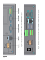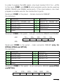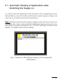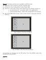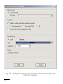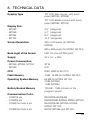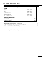
1
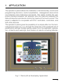
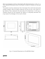
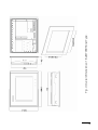
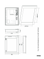
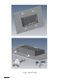
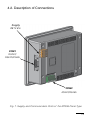
OPERATOR’S PANEL MT TYPE SERVICE MANUAL Contents 1. APPLICATION .................................................................... 5 2. PANEL SET ....................................................................... 6 3. BASIC REQUIREMENTS, OPERATIONAL SAFETY ........................... 7 4. PANEL FITTING .................................................................. 7 4.1 OVERALL DIMENSIONS AND FIXING WAY.............................. 7 4.2 DESCRIPTION OF CONNECTIONS........................................13 5. PANEL SETUPS ................................................................. 16 5.1 AUTOMATIC STARTING OF APPLICATIONS AFTER SWITCHING ..... THE SUPPLY VOLTAGE ON............................................... 17 6. PANEL MASTER SOFTWARE INSTALLATION .............................. 20 6.1 HARDWARE REQUIREMENTS............................................ 20 6.2 INSTALLATION.............................................................. 20 7. DESCRIPTION OF SELECTED PANEL MASTER PROGRAM FUNCTIONS ....................................................... 20 7.1 LOADING THE EXISTING PROJECT...................................... 20 7.2 CREATING THE NEW PROJECT........................................... 21 7.3 ADDING THE MODBUS TCP/IP CONNECTION.......................... 29 7.4 LOADING THE PROJECT INTO THE PANEL............................. 35 8. TECHNICAL DATA .............................................................. 39 9. ORDER CODES .................................................................. 41 10. MAINTENANCE AND GUARANTEE ........................................... 42 1. APPLICATION The operator’s panel allows the realization of all elementary control and programming functions, control visualization , management and control of production and measuring processes. The panel creates the graphical interface between the operator and the machine enabling the data introduction and device control by means of the touch screen. The panel is adapted to co-operate with PLC controllers, controllers, and with other devices. The operator’s panel gives the possibility of a simple affect on the technological process run, e.g. through the selection of the prepared set of parameters settings through giving values from the keyboard, generation of alarms and warnings, and creation of reports including substan- Fig. 1. Panel with an Exemplary Application tial changes of technological process parameters in time, e.g. for the manufacturer department of the production quality management. Advanced visualization functions, as animation, trend indications and measuring functions as canvassing, data storage and similar, increase considerably the panel efficiency, facilitate the operator work and optimize the control process. The advanced visualization and the rich set of functions contribute also to a minimalization of service errors, what has a direct influence on the product quality. The panel control algorithm is created on a PC computer for specific solutions of control systems, and next downloaded to the standard panel through a serial link. The very efficient programming tool Panel Master serves to design the control algorithm, this no requires the knowledge of any programming language, operating on any personal computer under the control of WINDOWS 2000/XP/ VISTA/7 systems. The tool software is equipped with communication drivers to many devices and with a rich library of functional modules, what enables in an easy way the panel function configuration, error diagnosis, design of dialogues with the user. The construction of control structures consists on the placement of ready library objects on project sheets and parameter setups of these objects acc. to requirements. 2. METER SET The set is composed of: - operator’s panel.......................................... 1 pc - clamps to fix in the panel............................ 4 pcs/8 pcs* - service manual............................................ 1 pc - guarantee card........................................... 1 pc - installation plate.......................................... 1 pc * for MT084 and MT104 When unpacking the operator’s panel, please check whether the type and execution code on the data plate correspond to the order. 3. BASIC REQUIREMENTS AND OPERATIONAL SAFETY In the safety service scope, the operator’s panel meets the requirements of the EN 61010-1 standard. Observations Concerning the Operational Safety: l All operations concerning transport, installation, and commissioning as well as maintenance, must be carried out by qualified, skilled personnel, and national regulations for the prevention of accidents must be observed. l Before switching the panel on, one must check the correctness of connection to the network. l Before removing the panel housing, one must switch the supply off and disconnect measuring circuits. l The removal of the panel housing during the guarantee contract period may cause its cancellation. l The panel is destined to be installed and used in industrial electromagnetic environment conditions. l One must remember that in the building installation a switch or a circuit-breaker should be installed. This switch should be located near the device, easy accessible by the operator, and suitably marked. 4. PANEL FITTING 4.1. Overal Dimensions and Fixing Way The panel is adapted to be fixed in a board acc. to the fig. 2 and 3. Housing dimensions: - MT035 130 106.2 36 mm - MT058 186.5 145.5 42 mm - MT084 232.5 175.8 50 mm - MT104 300 225 50 mm. One must prepare a hole in the board with dimensions acc. to fig. 2...5. The material thickness which the board is made of should not exceed 6 mm. The panel must be introduced from the board front with disconnected supply voltage. After the panel insertion into the cut-out, one must fix it by means of four clamps at the rear side of the board acc. to the fig. 6. Clamps should not be screwed too tightly or unequally because this may cause the damage of the touch screen. Fig. 2. Overall Dimensions of the MT035 Panel Fig. 3. Overal Dimensions of the MT058 Panel Type. 10 Fig. 4 Overall Dimensions of the MT084 Panel. 11 Fig. 5 Overall Dimensions of the MT104 Panel. Fig.6. Panel Fixing 12 4.2. Description of Connections Supply 24 V d.c. COM1 RS232/ RS422/RS485 COM2 RS422/RS485 Fig. 7. Supply and Communication Ports of the MT035 Panel Type 13 14 Fig. 9. Supply and Communication Ports of MT084 and MT104 Panel Types. Fig. 8. Supply and Communication Ports of the MT058 Panel Type. Supply In order to supply the HMI panel, one must connect 24 V d.c. ±10% to the input. COM1 and COM 2 communication ports can be used as RS232, RS422 and RS485 serial ports. If the need arises, one must prepare a suitable wire for the connection to ports. Serial port COM1 in the panel – female connector DB9-9P. Pin definition: Pin 1 2 3 4 5 Function RS422 TX+ i RS485 +(A) RS232 RXD RS232 TXD RS422 RX+ GND Pin 6 7 8 9 Function RS422 TX- i RS485 –(B) RS232 RTS RS232 CTS RS422 RX- Serial port COM2 in the panel – 4 (5) pin connector (RS422 and RS485) 422 TX+ RX+ 485 +(A) RX- TX- -(B) SG Serial port COM2 in the panel – male connector DB9-9P (only for MT058, MT084 and MT104). Pin definition: Pin 1 2 3 4 5 Function RS485 +(A) RS232 RXD RS232 TXD Pin 6 7 8 9 Function RS485 –(B) RS232 RTS RS232 CTS GND Serial port COM3 in the panel – 6 pin connector (RS232) (only MT084 and MT104). 5V CTS RTS TXD RXD SG 15 5. PANEL SETTINGS After switching the supply on, the panel displays the starting screen Panel Setup presented on the fig. 10. Choosing the General option, one can check or set common panel parameters, such as: battery checking, time of the screen killer, display mode of the starting screen, communication settings, language, brightness level of the LCD screen, and the IP address (if the panel is equipped with the Ethernet port). Fig. 10. Starting Screen: Panel Setup Choosing the touch panel option, one can adjust the working dimension of the touch screen but, one must carry out this function only in case of necessity. The Real Time Clock option allows to setup the Real time clock, however link1, link2 option allow to setup communication ports parameters suitably as COM1 and COM2. Pressing the Copy to option, one can copy the Project into another panel. To cross to the carry out application, one must press the Run button. 16 5.1. Automatic Starting of Applications after Switching the Supply on. In order to start the application with omission of the configuration menu (Setup Menu), every time after switching the panel supply voltage, one must carry out below mentionned operations. Step 1: Before switching the supply voltage, press the touch screen in the upper left corner, next switch the HMI panel during ca 3-5 sec. holding down the screen pressure (Fig. 11) till the hearing of a short sound (Beep). The BIOS mode will be started. Fig.11. Entrance in BIOS Mode at Setup of the Configuration (Setup Menu) 17 Step 2: Following options are available in BIOS mode: l updating of the operating system (Update OS) l entrance in the configuration menu (Panel OS) l selection of the start screen after switching the voltage supply on: o pressing Run AP – automatic start of the application o pressing Panel Setup – start of the configuration menu screen l test of the HMI panel (Test): LCD, touch screen, clock and internal memory. Fig. 12 Start in the Run AP Mode Fig. 13 Start in the Panel Setup Mode Acceptation of changes by the OK button. Exit from BIOS mode after pressing the Exit button. 18 Step 3: If the application (Run AP) has been set as the start screen, and we would restore the start of the configuration menu (Setup Menu), one must hold down the upper right screen corner (Fig. 14) during ca 3-5 sec. during switching the supply voltage on. After hearing a short sound (Beep), the configuration menu (Setup Menu) appears. A renewed switching of the supply on will cause the application start. Fig. 14 Single Calling of the Configuration Menu (Setup Menu) when Setting the Automatic Application Start (Run AP). 19 6. PANEL MASTER SOFTWARE INSTALLATION 6.1. Hardware Requirements Before the installation of the Panel Master software, one must check if the computer fulfils following hardware requirements: l at least, a Pentium III processor, l at least, 100 MB of access availability on the hard disk, l at least, 64 MB of system memory, l serial port or LAN necessary for the communication with the operator’s panel in order to transmit files to the panel, l CD installation disk , one can also collect the installation program from the Internet page http://www.lumel.com.pl, l Windows 2000/ XP/ VISTA operating system (system of the Unicode text). 6.2. Installation l on must close all programs before beginning the installation, click twice the setup.exe icone from the installation CD disk to start the installation program, l proceed acc. to instructions of the installation program, l default program catalogue:C:\Program Files\PanelMaster l 7. DESCRIPTION OF SELECTED PANEL MASTER PROGRAM FUNCTIONS 7.1. Loading in the Existing Project To load in the existing project, one must choose the Open... option from the File menu or click the 20 icone on the tool bar. The win- dow of project files will be displayed (fig. 15). One must choose the existing project xx.pmj and next click the Open buton. Fig. 15. Loading the Project from the File 7.2. Creating a New project To create a new Project, one must choose the New... option from the File menu, or click the icone on the tool bar. The window (fig. 16) will be displayed. One must give the file name of the new project and the file situation and next, click the Further> button. 21 Fig. 16. Creation of a New Project – Project Name In the succeeding window (fig. 17), one must choose the panel type: MT035-TST(Color) MT058-TST(Color), MT058-TNT(Color/Ethernet), MT084-TNT(Ethernet), MT104-TNT(Ethernet). and write in the panel name (Panel_1 by default), and next click the Further> button. Fig. 17. Creation of a New Project – Panel Type 22 The succeeding window (fig.18) will be displayed in which, one must define connection parameters with the co-operating device. Fig. 18. Parameters of Link Connection Link Name: connection name, e.g. RE20-RS; when a transmission error occurs, the connection name will be displayed in the error communication window. Link Type: the Direct Link (COM) connection type means the direct connection of the COM1 serial port with the device serial port. If the panel and the connected device are equipped with the Ethernet port, one can choose the Direct Link (Ethernet) connection type. 23 Link Port: defines panel ports acc. to the chosen operator’s panel type; one must choose the panel port, which the device is connected to. Device/Server: from the developed list, one must choose the suitable communication driver type for the connected device. In the presented above example, the RE20 controller with Modbus protocol in RTU mode is connected to the RS-485 serial port of the panel (COM1). The Project tree appears in the Project Manager window, and the window of the projected panel Screen 1, on the Panel 1 tag. The simple method of the screen edition proceeds in three steps presented below: 1.Click the icon of the chosen object on the tool bar. 2.Put the object in the suitable place on the projected screen. Adjust the object frame dimensions. 3.Click the right mouse key to display the Object Properties dialogue and set object properties, i.e. frame style, font, data type, address, function, etc. Example of a project to display the set value from the RE20 controller on the screen: 1.Click the Numeric Display icon on the tool bar or choose the Numeric Display option from the Object menu. 2.Place the mouse cursor in the chosen place in the Screen 1 and click the left mouse key. A rectangle with a numerical value appears on the screen. Readjust the rectangle dimensions to own needs. 3.Choose the Object Properties option by the right mouse key. The dialogue of Numeric Display object properties presented on the fig. 19 will be displayed. 24 OK Cancel Help Fig. 19. Properties of the Numeric Display Establish the shape and the colour of the frame with the numerical value, mark eventually the external label value description. Then, an extra External Label tag appears on which, one can write in the value description text and set the font and colour. 25 One must choose the type of downloaded data by the device in the Data Type field. For the RE20 controller there is a 16-bit Signed Int. Additionally, one can set a complete number of digits of the displayed value (Total Digits), the number of digits after the decimal point (Fractional Digits), the font and colour. In the Monitor Address field, one must choose the icon beside the field. The dialogue presented on the fig. 20 appears in which, one must give the data source. Fig. 20. Source Definition of Numerical Field Data In the upper selection field, one must choose the name of the Link connection, which data will originate from (RE20-RS here). The download frame is defined below: in turn, the address in the Modbus network, value type (W dla RE20) and the register number for the controller (4005 corresponds to the SP set value). Settings must be accepted by the ENT button. To terminate the definition of the Numeric Display object, press the OK button. 26 Choice of the floating point value. One must choose the type of downloaded data by the device in the Data Type field. For Lumel S.A. devices, that is the 32-bit Floating Point. One can set additionally the complete number of digits of the displayed quantity (Total Digits), the number of digits after the decimal point (Fractional Digits), the font and colour. Fig. 21. Data Type: Selection of the Data Type 27 Fig. 22. Establishment of the Address of the Float Point Type (for the Register Address 7000) for the Device nr 1 in the Modbus network. Fig. 23. Helping Window Presenting Possible Types of Variables. 28 7.3. Addition of the Modbus TCP/IP connection Fig. 24. Addition of a New Connection to the „Link” List. 29 OK Cancel Help Fig. 25. Setting of ‘General Properties”. Link Number: the program enables to set, up to 4 independent Ethernet connections using the Modus TCP/IP protocol. Link Name: name identifying the connection; when a transmission error occurs, the connection name will be displayed in the error communication window. Link Type: one must choose the Direct Link (Ethernet). Link Port: defines panel ports acc. to the chosen operator panel type; one must choose the panel port, which the device is connected to in the case of TCP/IP – Ethernet. Device/Server: from the developed list, one must choose the type of the suitable communication driver for the connected device. 30 OK Cancel Help Fig. 26. „Parameters Properties” Settings Establish Parameters of the TCP Connection. Address: device address – server in the Ethernet network, IP Address: device address – server in the Ethernet network, Port: Number of the TCP Port on which the data Exchange will be carried out. Node Address:device address – server. Parameter used when applying devices of Getwey Modbus TCP type, Retry Count: number of query repetitions in case when a transmission error appears. 31 Fig. 27. Correctly Added TCP Connection: TCP MODBUS 32 OK Cancel Help Fig. 28. Configuration Window of the variable displayed on the panel. 33 To choose the MODBUS connection, one must choose the configuration window of the variable displayed on the panel (calculator icon). Fig.29. Selection of the TCP MODBUS Connection Fig. 30. Correctly Configured Window of the 32-bit Variable of Float Type for the TCP MODBUS Connection Such prepared project, can be stored to the file (menu File->Save), and next loaded into the panel. 34 7.4. Loading the Project into the Panel To load the project into the panel, one must choose the Transfer Data to Panel... option or click the icon on the tool bar. The window presented on the fig. 31 will be displayed. Communication port (COM1) Fig. 31 Loading the Project into the Panel. 35 Communication port (COM1) Fig. 32. Loading the Project into the Panel when Connecting in the Ethernet Network. 36 Before loading the project into the panel, one must select the communication port (COM1...COM32) and the baud rate (Baudrate) when selecting the transmission through COM. However, if selecting the Ethernet option, one must give the IP address. After pressing the Start button, the project will be compiled, and next transmitted to the panel. If the loading does not succeed, one must check if the COM port is not occupied by other devices or if the panel if correctly switched to the local network on. The “Recommended” option records main files of the project. Fig. 33. The Option “All except OS0” loads all project files without system Files. 37 Fig. 34. The option “All” loads all project files with system files. The option is required in case of an erroneous programming of the panel, or a transmission break during the configuration loading. 38 8. TECHNICAL DATA Dysplay Type TFT LCD 256 colours, with touch panel (MT035, MT058) TFT LCD 65535 colours with touch panel (MT084, MT104) Display Size: - MT035 - MT058 - MT084 - MT104 3.5” (diagonal) 5.7” (diagonal) 8.4” (diagonal) 10.4” (diagonal) Screen Resolution 320 ´ 240 pixels (for MT035, MT058) 800 ´ 600 pixels (for MT084, MT104) Back Light of the Screen LED, life time 50 000 godz. Supply 24 V d.c. ±10%; Power Consumption: - MT058, MT084, MT104 - MT035 20 W 6W CPU RISC ARM 32 Bit CPU Flash Memory 4 MB, 16 MB (for MT084, MT104) Operating System Memory 64 MB for MT084, MT104 2 MB (MT058) 1 MB (MT035) Battery Backed Memory Communication Ports: - COM1/9 pin - COM2/9 pin - COM2/Terminal 5 pin - COM3/Terminal 6 pin 128 KB...1 MB (chosen in the program option) RS232/RS422/RS485 RS232/RS485 (MT058, MT084, MT104) RS422/RS485 (MT035, MT058, MT084, MT104) RS232 (MT084 and MT104) 39 - network Ethernet (TNT) - 2 x USB - 1 x USB Host v2.0 (MT084 and MT104) Host v1.1 (frontal panel) only MT104 Protection Level from Panel frontal Side IP 65 Operating Temperature 0... 50°C Storage temperature -20... 60°C Ambient Humidity 20... 90% RH (non-condensing) Vibration Endurance amplitude 0.5 mm, 10...55 Hz, 2 hours in X, Y, Z axis directions Shock endurance Weight: - MT035 - MT058 - MT084 - MT104 10 G, 11 ms three times in each X, Y, Z direction 0.3 kg 0.85 kg 0.9 kg 1.6 kg STANDARDS FULFILLED BY THE PANEL Electromagnetic Compatibility: - noise immunity EN 61000-6-2 - noise emissions EN 61000-6-4 40 9. ORDER CODES Operator’s Panel of MT TypeType: 3.5’’ 5.7’’ 5.7’’ Ethernet 8.4’’ Ethernet 10.4’’ Ethernet Kind of Execution: standard custom-made1) Acceptance tests: without an extra quality inspection with an extra quality inspection certificate acc. customer’s agreement1) XXX-XXX XX X 035-TST 058-TST 058-TNT 084-TNT 104-TNT 00 XX 8 7 X 1) - numbering will be established by the manufacturer 41 10. Maintenance and Guarantee This operator’s panel does not require any periodical maintenance. In case of some incorrect unit operations: From the Shipping Date, During the Period Given in the Annexed Guarantee Card One should take the instrument down from the installation and return it to the Manufacturer’s Quality Control Dept. If the instrument has been used in compliance with the instructions, the Manufacturer guarantees to repair it free of charge. After the Guarantee Period: One should turn over the instrument to repair in a certified service workshop. The disassembling of the housing causes the cancellation of the granted guarantee. The Manufacturer’s policy is one of continuous improvement and we reserve the right to make changes in design and specifications of any products as engineering advances or necessity requires and revise the above specification without notice. 42 43 SALES PROGRAM DIGITAL and BARGRAPH PANEL METERS MEASURING TRANSDUCERS ANALOG PANEL METERS (DIN INSTRUMENTS) MEASUREMENT CONTROL RECORDING INDUSTRIAL PROCESS and POWER CONTROLLERS CHART and PAPERLESS RECORDERS 1-PHASE and 3-PHASE WATT-HOUR METERS LARGE SIZE DISPLAY PANELS ELEMENTS OF INTEGRATION SYSTEMS ACCESSORIES for MEASURING INSTRUMENTS (SHUNTS and CURRENT TRANSFORMERS) CUSTOM-MADE PRODUCTS ACCORDING CUSTOMER’S REQUIREMENTS WE ALSO OFFER OUR SERVICES IN THE PRODUCTION OF: ALUMINIUM ALLOY PRESSURE CASTINGS PRECISION ENGINEERING and THERMOPLASTICS PARTS SUBCONTRACTING of ELECTRONIC DEVICES (SMT) PRESSURE CASTINGS and OTHER TOOLS QUALITY PROCEDURES: According to ISO 9001 and ISO 14001 international requirements. All our instruments have CE mark. For more information, please write to or phone our Export Department Lubuskie Zak³ady Aparatów Elektrycznych LUMEL S.A. ul. Sulechowska 1, 65-022 Zielona Góra, Poland Export Department: Tel.: (48-68) 329 53 02 Fax: (48-68) 325 40 91 e-mail: [email protected] 44 MT-07B Tel.: (48-68) 329 51 00 (exchange) Fax: (48-68) 329 51 01 e-mail:[email protected] http://www.lumel.com.pl