1
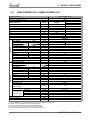
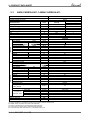
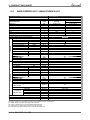
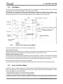
YUDE Series Indoor Units Outdoor Units CADE024 DBDE024 FADE024 YUDE024 CADE030 DBDE030 FADE030 YUDE030 CADE036 DBDE036 FADE036 YUDE036 CADE036 DBDE036 FADE036 YUDE036T REFRIGERANT HEAT PUMP R410A June-2013 SM YUDE 1-A.1 GB Version:1 LIST OF EFFECTIVE PAGES Note: Changes in the pages are indicated by a “Revision#” in the footer of each effected page (when none indicates no changes in the relevant page). All pages in the following list represent effected/ non effected pages divided by chapters. Dates of issue for original and changed pages are: Total number of pages in this publication is 117 consisting of the following: Page No. Revision No. # Page No. * Zero in this column indicates an original page. A | SM YUDE 1-A.1 GB Revision No. # Page No. Revision No. # Table of Contents 1. INTRODUCTION................................................................................................................................1-1 2. PRODUCT DATA SHEET ..................................................................................................................2-1 3. RATING CONDITIONS ......................................................................................................................3-1 4. OUTLINE DIMENSIONS ...................................................................................................................4-1 5. PERFORMANCE DATA.....................................................................................................................5-1 6. AIRFLOW CURVES...........................................................................................................................6-1 7. ELECTRICAL DATA .......................................................................................................................... 7-1 8. WIRING DIAGRAMS .........................................................................................................................8-1 9. REFRIGERATION DIAGRAMS ........................................................................................................9-1 10. TUBING CONNECTIONS ................................................................................................................10-1 11. CONTROL SYSTEM ........................................................................................................................ 11-1 12. TROUBLESHOOTING..................................................................................................................... 12-1 13. EXPLODED VIEWS AND SPARE PART LISTS.............................................................................13-1 14. APPENDIX .......................................................................................................................................14-1 SM YUDE 1-A.1 GB | B 1—INTRODUCTION 1. INTRODUCTION 1.1 General The YUDE series DC inverter is major designed for light commercial air-conditioning needs with the DC inverter technology, this series of products provides the most comfort and energy saving. This new line come with the comply to the new ECO Design regulation of 2014. • The outdoor can match following indoors: • -Indoor Floor/Ceiling DCI: 3 sizes including 24/30/36kBtu/h • -Indoor Cassette DCI: 3 sizes including 24/30/36Btu/h • -Indoor Ducted DCI:3 sizes including 24/30/36kBtu/h • The outdoor unit has two options of 1 phase/3 phases: • 1 Phase: 3 sizes including 24/30/36kBtu/h • 3 Phase: 36kBtu/h 1.2 Main Features • DCI R410A models • Auto mode. • SEER / SCOP A-A level for all models. • Cooling • Heating • Dehumidification • Sleep mode • ON/OFF timer • Auto swing (cassette and floor ceiling) • 4-dimension swing(cassette only ) • Intelligent deicing • Memory from power failure • Cold air prevention in heating • Self diagnostic (Error indications) for ease of maintenance • Outdoor -15 C for cooling 1—1 | SM YUDE 1-A.1 GB 1—INTRODUCTION 1.3. Indoor Unit The CADE indoor unit is ceiling mounted, the FADE indoor unit is ceiling or floor mounted, the DBDE indoor unit is a low silhouette ducted unit and can be easily fitted to many types of residential and commercials applications. It includes: • Coil with hydrophilic aluminum fins. • Motorized flaps (step motors) for CADE and FADE • Advanced electronic control box assembly 1.4 Filtration The series presents air filters: • Easily accessible, and re-usable pre-filters (mesh) 1.5 Control The microprocessor indoor controller, and an infrared remote control and wired controller, supplied as standard, provide complete operating function and programming. For further details please refer to the Operation Manual, Appendix A. SM YUDE 1-A.1 GB | 1—2 1—INTRODUCTION 1.6 Outdoor Unit The outdoor units can be installed as floor or wall mounted units by using a wall supporting bracket. The metal sheets are protected by anti- corrosion paint work allowing long life resistance. All outdoor units are pre-charged. For further information please refer to the Product Data Sheet, Chapter 2. It includes: • Compressor mounted in a soundproofed compartment: • Axial fan. • Outdoor coil with hydrophilic louver fins for RC units. • Outlet air fan grill. • Service valves ”flare” type connection. 1.7 Tubing Connections Flare type interconnecting tubing to be produced on site. For further details please refer to the Installation Manual, Chapter 10. 1.8 Accessories RCWE Wall Mounted Remote Control The RCWE remote control is mounted on the wall, and controls the unit either as an infrared remote control or as a wired controller. The wired controller can control up to 10 indoor units with the same program settings and adjustment. For further details please refer to the Technical Service Manual. 1.9 Inbox Documentation Each unit is supplied with its own installation and operation manuals. 1—3 | SM YUDE 1-A.1 GB 1—INTRODUCTION 1.10 Matching Table INDOOR UNITS OUTDOOR UNITS AWAU-YUDE024-H11 AWAU-YUDE030-H11 AWSI-DBDE024-N11 AWSI-DBDE030-N11 AWSI-DBDE036-N11 AWSI-CADE024-N11 AWSI-CADE030-N11 AWSI-CADE036-N11 AWSI-FADE024-N11 AWSI-FADE030-N11 AWSI-FADE036-N11 AWAU-YUDE036-H11 AWAU-YUDE036-H13 SM YUDE 1-A.1 GB | 1—4 2—PRODUCT DATA SHEET 2. PRODUCT DATA SHEET 2.1 AWSI-DBDE024-N11 // AWAU-YUDE024-H11 Model Indoor Unit Model Outdoor Unit Installation Method of Pipe Units Capacity (1) Pdesign SEER / SCOP (2) Energy efficiency class Annual energy consumption Tbiv Tol Power supply Circuit breaker rating(Indoor-Outdoor) Fan type & quantity Fan speeds H/M/L H/M/L Air flow (3) External static pressure Min-Max H/M/L Sound power level (4) H/M/L Sound pressure level (5) Moisture removal Condensate drain tube I.D Dimensions WxHxD Weight Package dimensions WxHxD Packaged weight Units per pallet Stacking height Refrigerant control Compressor type, model Fan type & quantity Fan speeds H/L Air flow H/L H/L Sound power level(4) H/L Sound pressure level(5) Dimensions WxHxD Weight Package dimensions WxHxD Packaged weight Units per pallet Stacking height Refrigerant type Refrigerant charge (standard connecting tubing length) Additional charge per 1 meter Liquid line Suction line Connections between units Max.tubing length Max.height difference Operation control type Heating elements Others kW kW W/W OUTDOOR INDOOR Characteristics (1) (2) (3) (4) (5) kWh o C o C V/Ph/Hz A RPM m3/hr Pa dB(A) dB(A) l/hr mm mm kg mm kg units units AWAU-DBDE024-N11 AWAU-YUDE024-H11 Flared Heating Cooling Average 7,0(2,2-8,5) 8,0(2,4-9,5) 7,0 7,0 5.1 3.8 A A 480 2579 N/A -7 N/A -15 220-240V/Single/50Hz 10-20 Centrifugal fan-2 1400/1300/1200/1000 1400/1300/1200/1000 25(0-100) 64 47/46/44/40 2,3 20mm 1239x268x558 34 1348x597x283 39 7 7 EEV Rotary DC Inverter Axial x 1 RPM m3/hr dB(A) dB(A) mm kg mm kg Units Units 4000 65 57 980x790x427 67 1083x855x488 72 6 2 R410A kg(5m) 2.2 gr / 1m In.(mm) In.(mm) m. m. 5m<L<30m 60g/m 3/8”(9.53) 5/8”(15.88) Max.30 Max.15 Remote control/Wired Remote control - kW Rating conditions in accordance with ISO 5151 and ISO 13253 (for ducted units). SEER / SCOP calculation accordance with EN14825. Airflow in ducted units; at nominal external static pressure. Sound power in ducted units is measured at air discharge. Sound pressure level measured at 1.4 meter distance from unit. 2—1 | SM YUDE 1-A.1 GB 2—PRODUCT DATA SHEET 2.2 AWSI-FADE024-N11 // AWAU-YUDE024-H11 Model Indoor Unit Model Outdoor Unit Installation Method of Pipe Characteristics Units Capacity Pdesign SEER / SCOP (2) Energy efficiency class Annual energy consumption Tbiv Tol Power supply Circuit breaker rating(Indoor-Outdoor) Fan type & quantity Fan speeds H/M/L H/M/L Air flow (3) External static pressure Min-Max H/M/L Sound power level (4) H/M/L Sound pressure level (5) Moisture removal Condensate drain tube I.D Dimensions WxHxD Weight Package dimensions WxHxD Packaged weight Units per pallet Stacking height Refrigerant control Compressor type, model Fan type & quantity Fan speeds H/L Air flow H/L H/L Sound power level(4) H/L Sound pressure level(5) Dimensions WxHxD Weight Package dimensions WxHxD Packaged weight Units per pallet Stacking height Refrigerant type Refrigerant charge (standard connecting tubing length) Additional charge per 1 meter Liquid line Suction line Connections between units Max.tubing length Max.height difference Operation control type Heating elements Others kW kW W/W OUTDOOR INDOOR (1) (1) (2) (3) (4) (5) kWh o C o C V/Ph/Hz A RPM m3/hr Pa dB(A) dB(A) l/hr mm mm kg mm kg units units AWAU-FADE024-N11 AWAU-YUDE024-H11 Flared Heating Cooling Average 7,0(2,4-8,2) 8,0(2,4-9,0) 7,0 7,0 5.1 3.8 A A 480 2579 N/A -7 N/A -15 220-240V/Single/50Hz 10-20 Centrifugal fan-2 1200/1000/900/800 1200/1000/900/800 0 62 49/48/46/40 2,5 17 1220x225x700 40 1343x823x315 50 6 6 EEV Rotary DC Inverter Axial x 1 RPM m3/hr dB(A) dB(A) mm kg mm kg Units Units 4000 65 57 980x790x427 67 1083x855x488 72 6 2 R410A kg(5m) 2.2 gr / 1m In.(mm) In.(mm) m. m. 5m<L<30m 60g/m 3/8”(9.53) 5/8”(15.88) Max.30 Max.15 Remote control/Wired Remote control - kW Rating conditions in accordance with ISO 5151 and ISO 13253 (for ducted units). SEER / SCOP calculation accordance with EN14825. Airflow in ducted units; at nominal external static pressure. Sound power in ducted units is measured at air discharge. Sound pressure level measured at 1.4 meter distance from unit. SM YUDE 1-A.1 GB | 2—2 2—PRODUCT DATA SHEET 2.3 AWSI-CADE024-N11 // AWAU-YUDE024-H11 Model Indoor Unit Model Outdoor Unit Installation Method of Pipe Characteristics Units Capacity Pdesign SEER / SCOP (2) Energy efficiency class Annual energy consumption Tbiv Tol Power supply Circuit breaker rating(Indoor-Outdoor) Fan type & quantity Fan speeds H/M/L H/M/L Air flow (3) External static pressure Min-Max H/M/L Sound power level (4) H/M/L Sound pressure level (5) Moisture removal Condensate drain tube I.D Dimensions WxHxD Weight Package dimensions WxHxD Packaged weight Units per pallet Stacking height Refrigerant control Compressor type, model Fan type & quantity Fan speeds H/L Air flow H/L H/L Sound power level(4) H/L Sound pressure level(5) Dimensions WxHxD Weight Package dimensions WxHxD Packaged weight Units per pallet Stacking height Refrigerant type Refrigerant charge (standard connecting tubing length) Additional charge per 1 meter Liquid line Suction line Connections between units Max.tubing length Max.height difference Operation control type Heating elements Others kW kW W/W OUTDOOR INDOOR (1) (1) (2) (3) (4) (5) kWh o C o C V/Ph/Hz A AWAU-CADE024-N11 AWAU-YUDE024-H11 Flared Heating Cooling Average 7,0(2,4-8,5) 8,0(2,4-9,5) 7,0 7,2 5.1 3.8 A A 480 2653 N/A -7 N/A -15 220-240V/Single/50Hz 10-20 Centrifugal fan-2 RPM m3/hr Pa dB(A) dB(A) l/hr mm mm kg mm kg units units 1300 RPM m3/hr dB(A) dB(A) mm kg mm kg Units Units 4000 65 57 980x790x427 67 1083x855x488 72 6 2 R410A kg(5m) 2.2 gr / 1m In.(mm) In.(mm) m. m. 5m<L<30m 60g/m 3/8”(9.53) 5/8”(15.88) Max.30 Max.15 Remote control/Wired Remote control - kW Rating conditions in accordance with ISO 5151 and ISO 13253 (for ducted units). SEER / SCOP calculation accordance with EN14825. Airflow in ducted units; at nominal external static pressure. Sound power in ducted units is measured at air discharge. Sound pressure level measured at 1.4 meter distance from unit. 2—3 | SM YUDE 1-A.1 GB 1300 0 62 47/46/42/38 2,5 25mm 840x840x240 26 963x963x325 32 6 6 EEV Rotary DC Inverter Axial x 1 2—PRODUCT DATA SHEET 2.4 AWSI-DBDE030-N11 // AWAU-YUDE030-H11 Model Indoor Unit Model Outdoor Unit Installation Method of Pipe Units Capacity (1) Pdesign SEER / SCOP (2) Energy efficiency class Annual energy consumption Tbiv Tol Power supply Circuit breaker rating(Indoor-Outdoor) Fan type & quantity Fan speeds H/M/L H/M/L Air flow (3) External static pressure Min-Max H/M/L Sound power level (4) H/M/L Sound pressure level (5) Moisture removal Condensate drain tube I.D Dimensions WxHxD Weight Package dimensions WxHxD Packaged weight Units per pallet Stacking height Refrigerant control Compressor type, model Fan type & quantity Fan speeds H/L Air flow H/L H/L Sound power level(4) H/L Sound pressure level(5) Dimensions WxHxD Weight Package dimensions WxHxD Packaged weight Units per pallet Stacking height Refrigerant type Refrigerant charge (standard connecting tubing length) Additional charge per 1 meter Liquid line Suction line Connections between units Max.tubing length Max.height difference Operation control type Heating elements Others kW kW W/W OUTDOOR INDOOR Characteristics (1) (2) (3) (4) (5) kWh o C o C V/Ph/Hz A RPM m3/hr Pa dB(A) dB(A) l/hr mm mm kg mm kg units units AWAU-DBDE030-N11 AWAU-YUDE030-H11 Flared Heating Cooling Average 8,3(2,4-8,7) 9,2(2,4-9,9) 8,3 7,6 5.1 3.8 A A 570 2800 N/A -7 N/A -15 220-240V/Single/50Hz 10-25 Centrifugal fan-2 1400/1300/1200/1000 1400/1300/1200/1000 37(0-100) 64 47/46/44/40 2,3 20mm 1239x268x558 34 1348x597x283 39 7 7 EEV Rotary DC Inverter Axial x 1 RPM m3/hr dB(A) dB(A) mm kg mm kg Units Units 4000 65 58 980x790x427 71 1083x855x488 76 6 2 R410A kg(5m) 2.4 gr / 1m In.(mm) In.(mm) m. m. 5m<L<30m 60g/m 3/8”(9.53) 5/8”(15.88) Max.30 Max.15 Remote control/Wired Remote control - kW Rating conditions in accordance with ISO 5151 and ISO 13253 (for ducted units). SEER / SCOP calculation accordance with EN14825. Airflow in ducted units; at nominal external static pressure. Sound power in ducted units is measured at air discharge. Sound pressure level measured at 1.4 meter distance from unit. SM YUDE 1-A.1 GB | 2—4 2—PRODUCT DATA SHEET 2.5 AWSI-FADE030-N11 // AWAU-YUDE030-H11 Model Indoor Unit Model Outdoor Unit Installation Method of Pipe Characteristics Units Capacity Pdesign SEER / SCOP (2) Energy efficiency class Annual energy consumption Tbiv Tol Power supply Circuit breaker rating(Indoor-Outdoor) Fan type & quantity Fan speeds H/M/L H/M/L Air flow (3) External static pressure Min-Max H/M/L Sound power level (4) H/M/L Sound pressure level (5) Moisture removal Condensate drain tube I.D Dimensions WxHxD Weight Package dimensions WxHxD Packaged weight Units per pallet Stacking height Refrigerant control Compressor type, model Fan type & quantity Fan speeds H/L Air flow H/L H/L Sound power level(4) H/L Sound pressure level(5) Dimensions WxHxD Weight Package dimensions WxHxD Packaged weight Units per pallet Stacking height Refrigerant type Refrigerant charge (standard connecting tubing length) Additional charge per 1 meter Liquid line Suction line Connections between units Max.tubing length Max.height difference Operation control type Heating elements Others kW kW W/W OUTDOOR INDOOR (1) (1) (2) (3) (4) (5) kWh o C o C V/Ph/Hz A RPM m3/hr Pa dB(A) dB(A) l/hr mm mm kg mm kg units units AWAU-FADE030-N11 AWAU-YUDE030-H11 Flared Heating Cooling Average 8,5(2,6-9,2) 9,2(2,4-9,9) 8,5 7,6 5.1 3.8 A A 583 2800 N/A -7 N/A -15 220-240V/Single/50Hz 10-25 Centrifugal fan-2 1500/1400/1200/1000 1500/1400/1200/1000 0 62 49/46/44/38 3,0 17 1420x245x700 48 1548x828x345 56 6 6 EEV Rotary DC Inverter Axial x 1 RPM m3/hr dB(A) dB(A) mm kg mm kg Units Units 4000 65 58 980x790x427 71 1083x855x488 76 6 2 R410A kg(5m) 2.4 gr / 1m In.(mm) In.(mm) m. m. 5m<L<30m 60g/m 3/8”(9.53) 5/8”(15.88) Max.30 Max.15 Remote control/Wired Remote control - kW Rating conditions in accordance with ISO 5151 and ISO 13253 (for ducted units). SEER / SCOP calculation accordance with EN14825. Airflow in ducted units; at nominal external static pressure. Sound power in ducted units is measured at air discharge. Sound pressure level measured at 1.4 meter distance from unit. 2—5 | SM YUDE 1-A.1 GB 2—PRODUCT DATA SHEET 2.6 AWSI-CADE030N11 // AWAU-YUDE030-H11 Model Indoor Unit Model Outdoor Unit Installation Method of Pipe Characteristics Units Capacity Pdesign SEER / SCOP (2) Energy efficiency class Annual energy consumption Tbiv Tol Power supply Circuit breaker rating(Indoor-Outdoor) Fan type & quantity Fan speeds H/M/L H/M/L Air flow (3) External static pressure Min-Max H/M/L Sound power level (4) H/M/L Sound pressure level (5) Moisture removal Condensate drain tube I.D Dimensions WxHxD Weight Package dimensions WxHxD Packaged weight Units per pallet Stacking height Refrigerant control Compressor type, model Fan type & quantity Fan speeds H/L Air flow H/L H/L Sound power level(4) H/L Sound pressure level(5) Dimensions WxHxD Weight Package dimensions WxHxD Packaged weight Units per pallet Stacking height Refrigerant type Refrigerant charge (standard connecting tubing length) Additional charge per 1 meter Liquid line Suction line Connections between units Max.tubing length Max.height difference Operation control type Heating elements Others kW kW W/W OUTDOOR INDOOR (1) (1) (2) (3) (4) (5) kWh o C o C V/Ph/Hz A AWAU-CADE030-N11 AWAU-YUDE030-H11 Flared Heating Cooling Average 8,3(2,6-9,2) 9,2(2,4-9,9) 8,3 7,6 5.1 3.8 A A 570 2800 N/A -7 N/A -15 220-240V/Single/50Hz 10-25 Centrifugal fan-2 RPM m3/hr Pa dB(A) dB(A) l/hr mm mm kg mm kg units units 1500 1500/ 0 63 49/48/45/40 3,0 25 840x840x320 31 963x963x409 38 5 5 EEV Rotary DC Inverter Axial x 1 RPM m3/hr dB(A) dB(A) mm kg mm kg Units Units 4000 65 58 980x790x427 71 1083x855x488 76 6 2 R410A kg(5m) 2.4 gr / 1m In.(mm) In.(mm) m. m. 5m<L<30m 60g/m 3/8”(9.53) 5/8”(15.88) Max.30 Max.15 Remote control/Wired Remote control - kW Rating conditions in accordance with ISO 5151 and ISO 13253 (for ducted units). SEER / SCOP calculation accordance with EN14825. Airflow in ducted units; at nominal external static pressure. Sound power in ducted units is measured at air discharge. Sound pressure level measured at 1.4 meter distance from unit. SM YUDE 1-A.1 GB | 2—6 2—PRODUCT DATA SHEET 2.7 AWSI-DBDE036-N11 // AWAU-YUDE036-H11 Model Indoor Unit Model Outdoor Unit Installation Method of Pipe Units Capacity (1) Pdesign SEER / SCOP (2) Energy efficiency class Annual energy consumption Tbiv Tol Power supply Circuit breaker rating(Indoor-Outdoor) Fan type & quantity Fan speeds H/M/L H/M/L Air flow (3) External static pressure Min-Max H/M/L Sound power level (4) H/M/L Sound pressure level (5) Moisture removal Condensate drain tube I.D Dimensions WxHxD Weight Package dimensions WxHxD Packaged weight Units per pallet Stacking height Refrigerant control Compressor type, model Fan type & quantity Fan speeds H/L Air flow H/L H/L Sound power level(4) H/L Sound pressure level(5) Dimensions WxHxD Weight Package dimensions WxHxD Packaged weight Units per pallet Stacking height Refrigerant type Refrigerant charge (standard connecting tubing length) Additional charge per 1 meter Liquid line Suction line Connections between units Max.tubing length Max.height difference Operation control type Heating elements Others kW kW W/W OUTDOOR INDOOR Characteristics (1) (2) (3) (4) (5) kWh o C o C V/Ph/Hz A RPM m3/hr Pa dB(A) dB(A) l/hr mm mm kg mm kg units units AWAU-DBDE036-N11 AWAU-YUDE036-H11 Flared Heating Cooling Average 10,0(3,2-11,5) 12,0(2,9-14,5) 10,0 10,4 5.1 3.8 A A 687 3832 N/A -7 N/A -15 220-240V/Single/50Hz 10-32 Centrifugal fan-2 2100/1950/1800/1700 2100/1950/1800/1700 37(0-150) 64 53/52/48/44 2,3 20mm 1226x290x775 46 1338x877x305 63 6 6 EEV Rotary DC Inverter Axial x 1 RPM m3/hr dB(A) dB(A) mm kg mm kg Units Units 5300 70 63 1107x1100x440 92 1158x1235 x493 100 6 2 R410A kg(5m) 3,5 gr / 1m In.(mm) In.(mm) m. m. 5m<L<30m 60g/m 3/8”(9.53) 5/8”(15.88) Max.30 Max.15 Remote control/Wired Remote control - kW Rating conditions in accordance with ISO 5151 and ISO 13253 (for ducted units). SEER / SCOP calculation accordance with EN14825. Airflow in ducted units; at nominal external static pressure. Sound power in ducted units is measured at air discharge. Sound pressure level measured at 1.4 meter distance from unit. 2—7 | SM YUDE 1-A.1 GB 2—PRODUCT DATA SHEET 2.8 AWSI-FADE036-N11 // AWAU-YUDE036-H11 Model Indoor Unit Model Outdoor Unit Installation Method of Pipe Units Capacity (1) Pdesign SEER / SCOP (2) Energy efficiency class Annual energy consumption Tbiv Tol Power supply Circuit breaker rating(Indoor-Outdoor) Fan type & quantity Fan speeds H/M/L H/M/L Air flow (3) External static pressure Min-Max H/M/L Sound power level (4) H/M/L Sound pressure level (5) Moisture removal Condensate drain tube I.D Dimensions WxHxD Weight Package dimensions WxHxD Packaged weight Units per pallet Stacking height Refrigerant control Compressor type, model Fan type & quantity Fan speeds H/L Air flow H/L H/L Sound power level(4) H/L Sound pressure level(5) Dimensions WxHxD Weight Package dimensions WxHxD Packaged weight Units per pallet Stacking height Refrigerant type Refrigerant charge (standard connecting tubing length) Additional charge per 1 meter Liquid line Suction line Connections between units Max.tubing length Max.height difference Operation control type Heating elements Others kW kW W/W OUTDOOR INDOOR Characteristics (1) (2) (3) (4) (5) kWh o C o C V/Ph/Hz A RPM m3/hr Pa dB(A) dB(A) l/hr mm mm kg mm kg units units AWAU-FADE036-N11 AWAU-YUDE036-H11 Flared Heating Cooling Average 10,0(3,2-11,5) 12,0(2,9-14,5) 10,0 10,4 5.1 3.8 A A 687 3832 N/A -7 N/A -15 220-240V/Single/50Hz 10-32 Centrifugal fan-2 1900/1630/1520/1350 1900/1630/1520/1350 0 65 54/53/51/46 3,8 17 1420x245x700 48 1548x828x345 56 6 6 EEV Rotary DC Inverter Axial x 1 RPM m3/hr dB(A) dB(A) mm kg mm kg Units Units 5300 70 63 1107x1100x440 92 1158x1235 x493 100 6 2 R410A kg(5m) 3,5 gr / 1m In.(mm) In.(mm) m. m. 5m<L<30m 60g/m 3/8”(9.53) 5/8”(15.88) Max.30 Max.15 Remote control/Wired Remote control - kW Rating conditions in accordance with ISO 5151 and ISO 13253 (for ducted units). SEER / SCOP calculation accordance with EN14825. Airflow in ducted units; at nominal external static pressure. Sound power in ducted units is measured at air discharge. Sound pressure level measured at 1.4 meter distance from unit. SM YUDE 1-A.1 GB | 2—8 2—PRODUCT DATA SHEET 2.9 AWSI-CADE036-N11 // AWAU-YUDE036-H13 Model Indoor Unit Model Outdoor Unit Installation Method of Pipe Units Capacity (1) Pdesign SEER / SCOP (2) Energy efficiency class Annual energy consumption Tbiv Tol Power supply Circuit breaker rating(Indoor-Outdoor) Fan type & quantity Fan speeds H/M/L H/M/L Air flow (3) External static pressure Min-Max H/M/L Sound power level (4) H/M/L Sound pressure level (5) Moisture removal Condensate drain tube I.D Dimensions WxHxD Weight Package dimensions WxHxD Packaged weight Units per pallet Stacking height Refrigerant control Compressor type, model Fan type & quantity Fan speeds H/L Air flow H/L H/L Sound power level(4) H/L Sound pressure level(5) Dimensions WxHxD Weight Package dimensions WxHxD Packaged weight Units per pallet Stacking height Refrigerant type Refrigerant charge (standard connecting tubing length) Additional charge per 1 meter Liquid line Suction line Connections between units Max.tubing length Max.height difference Operation control type Heating elements Others kW kW W/W OUTDOOR INDOOR Characteristics (1) (2) (3) (4) (5) kWh o C o C V/Ph/Hz A AWAU-CADE036-N11 AWAU-YUDE036-H11 Flared Heating Cooling Average 10,0(3,2-11,5) 12,0(2,9-14,5) 10,0 10,4 5.1 3.8 A A 687 3832 N/A -7 N/A -15 220-240V/Single/50Hz 10-32 Centrifugal fan-2 RPM m3/hr Pa dB(A) dB(A) l/hr mm mm kg mm kg units units 1850 RPM m3/hr dB(A) dB(A) mm kg mm kg Units Units 5300 70 63 1107x1100x440 92 1158x1235 x493 100 6 2 R410A kg(5m) 3,5 gr / 1m In.(mm) In.(mm) m. m. 5m<L<30m 60g/m 3/8”(9.53) 5/8”(15.88) Max.30 Max.15 Remote control/Wired Remote control - kW Rating conditions in accordance with ISO 5151 and ISO 13253 (for ducted units). SEER / SCOP calculation accordance with EN14825. Airflow in ducted units; at nominal external static pressure. Sound power in ducted units is measured at air discharge. Sound pressure level measured at 1.4 meter distance from unit. 2—9 | SM YUDE 1-A.1 GB 1850 0 63 51/49/46/43 3,8 25mm 840x840x320 31 963x963x409 38 5 5 EEV Rotary DC Inverter Axial x 1 3—RATING CONDITIONS 3. RATING CONDITIONS Rating conditions in accordance with ISO 5151 and ISO 13253 (for ducted units). Cooling: Indoor: 27oC DB 19oC WB Outdoor: 35 oC DB Heating: Indoor: 20oC DB Outdoor: 7oC DB 6oC WB 3.1 Operating Limits R410A Indoor Cooling Heating Voltage Outdoor Upper limit 32oC DB 23oC WB 48oC DB Lower limit 21oC DB 15oC WB -15oC DB Upper limit 27oC DB 24oC DB 18oC WB Lower limit 10oC DB -15oC DB 1PH 198 – 264 V 3PH 360 – 440 V SM YUDE 1-A.1 GB | 3—1 4—OUTLINE DIMENSIONS 4. OUTLINE DIMENSIONS 4.1 CADE024-030-036 Unit:mm Model A B C D E F CADE024 950 840 780 680 160 240 CADE030/036 950 840 780 680 160 320 4.2 DBDE 024-030-036 Unit: mm A B C D E F G H I J DBDE024 1101 515 820 1159 1239 558 1002 160 235 268 DBDE030 1101 515 820 1159 1239 558 1002 160 235 268 DBDE036 1011 748 820 1115 1226 775 979 160 231 290 4—1 | SM YUDE 1-A.1 GB 4—OUTLINE DIMENSIONS 4.3 FADE024-030-036 B A Unit: mm Model A B C D H FADE024 1220 225 1158 280 700 FADE030 1420 245 1354 280 700 FADE036 1420 245 1354 280 700 SM YUDE 1-A.1 GB | 4—2 4—OUTLINE DIMENSIONS 4.4 Outdoor Unit: Unit: mm Model A B C D E YUDE024 980 427 790 610 390 YUDE030 980 427 790 610 390 YUDE036 1107 440 1100 631 400 4—3 | SM YUDE 1-A.1 GB 5—PERFORMANCE DATA PERFORMANCE DATA PA GE UN DE R W OR K 5. SM YUDE 1-A.1 GB | 5—1 6—AIRFLOW CURVES 6. AIRFLOW CURVES 6.1 Model: AWSI-DBDE024-N11 Nominal System Curve Max System Curve Airflow Vs. External Static Pressure High speed 100 Medium Speed External Static Pressure (Pa) 90 Low Speed Operating Range 80 70 60 50 Performance test point at 50 Pa 40 30 20 10 0 800 1000 1200 1400 1600 1800 Airflow Rate,(m ³/ hr) 6.2 Model: AWSI-DBDE030-N11 Nominal System Curve Max System Curve Airflow Vs. External Static Pressure High speed 100 Medium Speed External Static Pressure (Pa) 90 Low Speed Operating Range 80 70 60 50 Performance test point at 50 Pa 40 30 20 10 0 800 1000 1200 Airflow Rate,(m ³/ hr) 6—1 | SM YUDE 1-A.1 GB 1400 1600 1800 6—AIRFLOW CURVES 6.3 Model: AWSI-DBDE036-N11 Nominal System Curve Max System Curve Airflow Vs. External Static Pressure High speed 150 Medium Speed 140 Low Speed External Static Pressure (Pa) 130 Operating Range 120 110 100 90 80 Performance test point at 50 Pa 70 60 50 40 30 20 10 0 1200 1400 1600 1800 2000 2200 2400 2600 Airflow Rate,(m ³/ hr) SM YUDE 1-A.1 GB | 6—2 7—ELECTRICAL DATA 7. ELECTRICAL DATA MODEL AWAU-YUDE024-H11 AWAU-YUDE030-H11 1~/220-240V/50Hz Capability of Air Switch(A) (Indoor) Power Supply Wiring No. X Cross Section mm2 (ODU) 3~/380-415V/ 50Hz 10A 20A 25A 32A 3x4.0mm2 32A 5x2.5mm2 Power Supply Wiring No. X Cross Section mm2 (IDU) 3 x1.5mm2 Interconnecting Cable Model No. X Cross Section mm2 2x0.75mm2 NOTE Power wiring cord should comply with local lows and electrical regulations requirements. 7—1 | SM YUDE 1-A.1 GB AWAU-YUDE036-H13 Separately Power Supply Capability of Air Switch(A) (Outdoor) AWAU-YUDE036-H11 8—WIRING DIAGRAMS WIRING DIAGRAMS AWAU-YUDE024-H11, AWAU-YUDE030-H11 M P 8.1 P 8. SM YUDE 1-A.1 GB | 8—1 8—WIRING DIAGRAMS 8.2 AWAU-YUDE036-H11 8—2 | SM YUDE 1-A.1 GB 8—WIRING DIAGRAMS AWAU-YUDE036-H13 (TBD) PA GE UN DE R W OR K 8.3 SM YUDE 1-A.1 GB | 8—3 8—WIRING DIAGRAMS AWSI-CADE024/030/036-N11 For model 30-42 8.4 8—4 | SM YUDE 1-A.1 GB N N H2 H1 2 1 XT2 PE L2 YEGN PE YEGN OG BU BK RD 15K E500 T2 AC-N(X500) BU T3 Indoor Coil Thermistor 20K PUMP-C WH ERROR (X5) N2(X6) ALARM OUTPUT Optional DC MOTOR Only for Model 48-60 BRACKET PE YEGN 6 PE YEGN Door Card Optional Human Detector 9 DISP5 Receiving Board EVAPORATOR M1 5 RCW4 COM-BMS2 COM-BMS3 DC-MOTOR1 DISP4 COM-BMS1 ModBUS M3 STEP MOTOR M2 U-SWING1 U-SWING2 AP1 AC-L(X501) RD Remark:The Wired Controller is the Room Air optional accessory. Thermistor The evaporator and the bracket only for From 09Kto24K unit should be grounded! AP2 WIRE X1 CONTROL X2 OUTDOOR 1 2 UNIT L L L1 COM6 COM7 XT1 INDOOR UNIT CN 23 8.5 DOOR-C POWER 8—WIRING DIAGRAMS AWSI-FADE024/030/036-N11 SM YUDE 1-A.1 GB | 8—5 8—WIRING DIAGRAMS 8.6 AWSI-DBD024/030/036-N11 8—6 | SM YUDE 1-A.1 GB 9—REFRIGERATION DIAGRAMS 9. REFRIGERATION DIAGRAMS OAT RAT OCT ICT CTT Note: CTT: Compressor Discharging Temperature Sensor OCT: Outdoor Coil Temperature Sensor OAT: Outdoor Air Temperature Sensor ICT: Indoor Coil Temperature Sensor RAT: Room Air Temperature Sensor SM YUDE 1-A.1 GB | 9—1 10—TUBING CONNECTIONS 10. TUBING CONNECTIONS When the outdoor unit is installed above the indoor unit an oil trap is required every 5m along the suction line at the lowest point of the riser. In case the indoor unit is installed above the outdoor, no trap is required. 10—1 | SM YUDE 1-A.1 GB 11—CONTROL SYSTEM 11. CONTROL SYSTEM 11.1 Electronic Control 11.1.1 Abbreviations Abbreviation A/C BMS PWR CTT DCI EEV HE HMI HST Hz ICT IDU MCU OAT OCT ODU OFAN PFC RAC RC RGT RPS RV SB,STBY SUCT S/W TBD TMR 11.1.2 Definition Air Condition Building Management System System Power Compressor Top Temperature sensor DC Inverter Electronic Expansion Valve Heating Element Human Machine Interface Heat Sink Temperature sensor Hertz (1/sec) – electrical frequency Indoor Coil Temperature (RT2) sensor Indoor Unit Micro Controller Unit Outdoor Air Temperature sensor ODU Coil Temperature sensor Outdoor Unit Outdoor Fan Power Factor Corrector Residential A/C Reverse Cycle (Heat Pump) Return Gas Temperature sensor Rounds per second (mechanical speed) Reverse Valve Stand By Compressor Suction Temperature sensor Software To Be Defined Timer System Operation Concept The control function is divided between indoor and outdoor unit controllers. Indoor unit is the system ‘Master’, requesting the outdoor unit for cooling/heating capacity supply. The outdoor unit is the system ‘Slave’ and it must supply the required capacity unless it enters into a protection mode avoiding it from supplying the requested capacity. Target frequency is transferred via indoor to outdoor communication, and the calculation is based on room temperature and set point temperature. 11.1.3 Compressor Frequency Control The Compressor Frequency Control is based on the PI scheme. When starting the compressor, or when conditions are varied due to the change of the room condition, the frequency must be initialized according to the ΔD value of the indoor unit and the Q value of the indoor unit. Q value: Indoor unit output determined from indoor unit capacity, air flow rate and other factors. SM YUDE 1-A.1 GB | 11—1 11—CONTROL SYSTEM 1. P control Calculate ΔD value in each sampling time (20 seconds), and adjust the frequency according to its difference from the frequency previously calculated. 2. I control If the operating frequency is not change more than a certain fixed time, adjust the frequency up and down according to the ΔD value. Obtaining the fixed ΔD value When the ΔD value is small- decrease the frequency When the ΔD value is large- increase the frequency 3. Frequency management when other controls are functioning When frequency is drooping; Frequency management is carried out only when the frequency droops. For limiting lower limit Frequency management is carried out only when the frequency rises. 4. Maximum and minimum limits of frequency by PI control The frequency upper and lower limits are set depending on indoor unit. When low noise commands come from the indoor unit or when outdoor unit low noise or quiet commands come from indoor unit, the upper limit frequency must be lowered than the usual setting. 11.1.3.1 Frequency range The compressor frequency limitation is set by the following table Minimum Frequency(MinFreq) Mode YUDE024 YUDE030 YUDE036 YUDE036T Cooling 20 20 20 20 Heating 20 20 20 20 11.1.3.2 Frequency Changes Control Frequency change rate is 1 Hz/sec. 11.1.3.3 Minimum On and Off Time Prohibit turning ON the compressor for 3 minutes after turning it off.(except during deicing protection) 11—2 | SM YUDE 1-A.1 GB 11—CONTROL SYSTEM 11.1.4 Indoor Fan Control 4 Indoor fan speeds are determined for each model. In high/ medium/ low indoor fan user setting, unit will operate fan in selected speed. In Auto Fan user setting, fan speed will be adjusted automatically according to the difference between actual room temperature(RAT) and user set point temperature(SPT). Indoor Fan speed RAT-SPT High Medium Low Cooling >=2 (0,2) <=0 Heating <=1 (1,3) >=3 In DRY mode, the automatic fan speed is forced to be low. 11.1.4.1 Turbo Speed In COOL and HEAT mode (not available in AUTO, DRY, FAN mode), press the Turbo button, the super high fan speed is selected on Remote control and the indoor fan rotates at high speed. 11.1.5 Outdoor Fan Control 11.1.5.1 OFAN Speed Type The outdoor fan motor is DC motor with 10 defined speeds. 11.1.5.2 General rules 1. The outdoor fan is ON when compressor ON during cooling,dring and heating mode. 2. When the unit is off by remote control, in safety stops and stop after reaching to the temperature point, the outdoor fan stops; 3. The outdoor fan is ON 30 sec ahead compressor start 4. Outdoor fan OFF will delay 60sec when compressor is OFF during cooling, dring and heating mode. 11.1.5.3 OFAN control in cooling mode: If HPS2 is cut off (Pressure higher than 3.0Mpa), the OFAN will go to high fan speed. If the HPS2 is recovery (pressure is 2.4MPa), the OFAN speed will reduce by 1 speed until the pressure is reaching 3.0MPa. This control is performed every 1 hour or pressure is below 2.4MPa. 11.1.5.4 OFAN control in heating mode: OFAN will keep high fan speed 11.1.6 Refrigerant control 11.1.6.1 EEV is used for all model 1. EEV operation after power-on: When power on, EEV will open 240steps and then move back with 540steps. This position will be recognized as 0. Then EEV will open to 480 steps and be ready for system operating. 2. EEV openloop depends on OAT,RAT,SPT and compressor frequency after compressor starts to operate. 3. Target CTT control will be performed after compressor operates for 5min. 4. The EEV opening will be updated every 5s. SM YUDE 1-A.1 GB | 11—3 11—CONTROL SYSTEM 11.1.7 Reversing Valve (RV) Control Reversing valve is on in heat mode. RV ON will delay 10 sec when compressor is ON and Switching of RV state is done only after compressor is off for over 2 minutes. 11.2 Fan Mode In this mode, the indoor fan may run at high,medium,low and automatic speed. The compressor, outdoor fan and 4-way valve will be OFF. In this mode, the range of setting temperature is 16~30C 11.3 Cool Mode If Load>0, the unit starts cooling operation. In this case, the compressor and outdoor fan will operate and the indoor fan will run at the setting speed. If Load≤0, the compressor will stop operation and the outdoor fan will delay 60 seconds to stop. While the indoor fan will run at the setting speed. 11.3.1 Indoor Fan operation under Cool Mode The indoor fan will run at high speed for 5 seconds before it is put into operation according to the setting then run at the setting speed. In Auto Fan user setting, fan speed will be adjusted automatically according to the SPT and RAT, refer to 11.1.5 11—4 | SM YUDE 1-A.1 GB 11—CONTROL SYSTEM 11.4 Heat Mode If Load >0, the unit will operate in heating mode. The compressor, outdoor fan and 4-way valve will operate and the indoor fan will delay 1’30” to start at the latest If LoadAT≤0, the compressor will stop operation and the outdoor fan will delay 60 seconds to stop. And the indoor fan will blow for 60s at low fan speed for cassette and floor ceiling model and at setting fan speed for duct model. During this period, the fan speed can’t be switched. 11.4.1 Indoor Fan Control in Heat Mode Indoor fan speed depends on the indoor coil temperature Anti-cold air function When starting the heating mode, anti-cold air function will be activated and indoor fan can run at low speed or stop running. This function will terminate after the unit runs for 1.5min. Residual heat blowing function During heating, when the stopping condition for the compressor is reached. The indoor fan will blow for 60s at low fan speed for floor ceiling model and at setting fan speed for duct model. For cassette unit the indoor fan will operate continuously in low fan speed until compressor restarting. During this period, the fan speed can’t be switched. For manual OFF condition, the residual heat blowing function will last 60s for all indoor models. 11.5 Auto Cool/Heat Mode In AUTO mode, the system selects the running mode (COOL/HEAT/FAN) automatically according to the room temperature. The display shows the actual running mode and setting temperature. There will be 30s delay for mode conversion. 1. When RAT≥26 degree, the cooling mode is selected. 2. When RAT≤20 degree, the unit runs in heating mode 3. When 20 degree <RAT< 26 degree, upon initial startup, the unit will enter auto mode and run in automatic fan mode. If the other mode changes into auto mode, the previous running mode will remain. SM YUDE 1-A.1 GB | 11—5 11—CONTROL SYSTEM 11.6 Dry Mode The dry mode is basically same as cooling mode. The difference is that: a) The indoor fan is fixed at low speed. b) Max. Capacity output: A×90% 11.7 Oil return When the unit is operating in low frequency for long time, the compressor will be forced to decrease frequency for 4 min to make sure the oil, which accumulated into the system, back to compressor. During the oil return operation, the IDU has no any indication 11.8 Protections There are 4 protection codes. Normal (Norm) – unit operate normally. Stop Rise (SR) – compressor frequency can not be raised but does not have to be decreased. HzDown – Compressor frequency is reduced by 2Hz/s Stop Compressor (SC) – Compressor is stopped. 11—6 | SM YUDE 1-A.1 GB 11—CONTROL SYSTEM 11.8.1 Indoor Coil Defrost Protection Conditions for Start Controlling Judge the controlling start with the ICT (Indoor Coil Temperature) in cool and dry mode after compressor is on for 15min to allow the operating frequency limitation and then prevent freezing of the indoor heat exchanger. Compressor will stop when ICT <= ICTdefrost for continuous 3 mins, it can resume running automatically when ICT >=10. 11.8.2 Model ICTdefrost Duct -2 Floor ceiling -4 Cassette -5 High Pressure Protection of Compressor by high pressure switch When high pressure protection is detected for 3 seconds continuously, the high pressure switch is 4.2Mpa, the unit will stop and report the fault, it can not resume running automatically and display malfunction, it can resume by pressing ON/OFF. 11.8.3 Compressor over Heating Protection If the discharge temperature rises above a certain level, the operating frequency upper limit is set to keep this temperature from going up further. Compressor will stop when CTT reaches 130. The unit can only resume running until the compressor has stopped for 3 minutes and the CTT is lower than 90. If the unit stops as such protection for 3 times, it can not resume running automatically and display malfunction, it can resume by pressing ON/OFF. 11.8.4 Compressor over Current Protection Detect an input current by the CT during the compressor is running, and set the frequency upper limit from such input current. In case of heat pump model, this control is the upper limit control function of the frequency which takes priority of the lower limit of four way valve activating compensation. 11.8.5 Model Current(A) YUDE024 45 YUDE030 45 YUDE036 38 YUDE036T 11.5 Outdoor Coil Deicing Protection This protection is for Heat Pump Only This protection is carried out by the cooling cycle (reverse cycle). The defrosting time or outdoor heat exchanger temperature must be more than its setting values when finishing the deicing protection. In the deicing protection, IFAN is forced OFF. SM YUDE 1-A.1 GB | 11—7 11—CONTROL SYSTEM 11.8.5.1 Deicing Starting Conditions The starting conditions must be made with the outdoor air temperature (OAT) and outdoor coil temperature (OCT). Under the conditions that the system is in heating operation, after the time for defrosting is judged to be satisfied, if the temperature for deicing is satisfied after detections for continuous 3minutes, the deicing operation will start. Deicing interval time is changed as a function of deicing time. If deicing time is shorter than former deicing time, the deicing interval time will be increased. If deicing time is longer than former deicing time, the deicing interval time will be decreased. 11.8.5.2 Deicing Protection Procedure 11.8.5.3 Exiting Deicing The deicing operation can exit when any of the conditions below is satisfied: 1. OCT>=10°C 2. OCT>=6°C lasts for more than 80s 3. The continuous running time of deicing reaches to 10min. 11.8.6 Condensate Water Over Flow Protection for cassette Outdoor unit receives “overflow’ signal from the indoor side. In cooling and dry mode, the pump is always on with the compressor on. And the pump will be on for 10 min after the compressor is off, in heating mode, the pump is off except that the overflow fault occurs. 11—8 | SM YUDE 1-A.1 GB 11—CONTROL SYSTEM Overflow when unit is ON Overflow Water Level Overflow when unit is OFF Normal ON OPER LED OFF BLINK ANY NLOAD NLOAD is forced to 0 0 ON PUMP OFF 10 min 11.8.7 10 min 10 min Communication malfunction If the ODU does not receive correct signal from indoor unit for 30 seconds continuously, or if the indoor unit does not receive message from outdoor unit for 1 minute, the unit will stop as communication malfunction protection; if communication malfunction resume and compressor has stopped for 3min, the unit will resume running. 11.8.8 IPM module protection When the compressor starts, if there is over current or control voltage low for IPM module as some abnormal results, IPM will detect module protection signal as the unit is on. Once the module protective signal is detected, stop the unit with module protection immediately. If the module protection is resumed and compressor has stopped for 3min, the unit will be allowed to operate. If the module protection continuously occurs for 3 times, it should not be resumed automatically, and you should press the ON/OFF button to resume. 11.8.9 Module overheating protection If the module temperature is higher than 100°C, the unit will stop. If module temperature is lower than 100°C, and compressor has stopped for 3min, the unit will resume operating. If the unit stops as module overheating protection for 6 times, it can not resume running automatically and display malfunction, it can resume by pressing ON/OFF. 11.8.10 Compressor overload protection The Over Load Protector is used to detect the compressor’s shell temperature. If the compressor temperature rises above a certain level, the compressor OLP will be cut off. Which will happen within 3 seconds continuously, the unit will stop and report fault. The unit will restart after 3 min if the fault is eliminated. If the unit stops as such protection for 3 times in 30 min, it can not resume running automatically and display malfunction, it can resume by pressing ON/OFF. SM YUDE 1-A.1 GB | 11—9 11—CONTROL SYSTEM 11.9 Operating the Unit from the ON/OFF Button The ON/OFF button allows to operate the unit in AUTO mode, the microcomputer will monitor the room temperature and select the (COOL, HEAT, FAN) mode automatically, and temperature/Fan speed settings can not be changed. 11.10 Indoor Unit Controllers and Indicators The following is schematic drawing for the display: CADE: Power Indication Lights up when the Air Conditioner is Power ON , Run Indication Lights up when the compressor is ON. Timer Indication Lights up when the Timer is set Auto Press the Auto button the unit will run auto mode automatically when the unit is off. Press the AUTO button, the air conditioner will stop when it is on Test When pressing it, the air conditioner will be forced to operate or stop. Do not press it when air conditioner is in normal operation. 2x7-Segments display 1. In normal situation, the setting temperature is displayed. 2. Shows indoor temperature when receiving the corresponding demand from controller. It resumes displaying setting temperature 5s later. 3. Shows the alarm code whenever there is an alarm. (Refer to Diagnostics part). 11—10 | SM YUDE 1-A.1 GB 11—CONTROL SYSTEM FADE: Power indication Lights up when the unit is connected to power Timer indication Lights up when the Timer is set Cool indication Lights up when the unit is running in cooling mode Heat indication Lights up when the unit is running in heat mode In normal situation, the setting temperature is displayed. 2. Shows indoor temperature when receiving the corresponding demand from controller. It resumes displaying setting temperature 5s later 3. Shows the alarm code whenever there is an alarm. (Refer to 1. 2x7-Segments display Diagnostics part) 11.11 Forced Mode (Compulsory operating function). Entering into forced mode : After the unit is powered for 5mins, press the light button on remote controller for 3 times in 3s successively to enter into Freon recovery mode. Fo will be displayed. When Freon recovery mode operated for 25mins, all loads will operate in cooling mode. (The setting fan speed is high fan speed and the setting temperature is 16C ) Exiting forced mode: Any signal from remote controller or button will exit the forced mode, and then the unit will operate at the current setting command. Forced mode will also be exited after operating for 25mins and then the unit will be turned off. SM YUDE 1-A.1 GB | 11—11 11—CONTROL SYSTEM 11.12 Characteristics of sensor 11.12.1 RAT/OAT RAT/OAT R-T chart 140 130 120 110 Resistance(Kohm) 100 90 80 70 60 50 40 30 20 10 0 -20 -15 -5 -10 5 0 10 20 15 25 30 35 40 45 50 55 60 65 70 Temperature(C) 11.12.2 ICT/OCT ICT/OCT R-T Chart 180 170 160 150 140 Resistance(Kohm) 130 120 110 100 90 80 70 60 50 40 30 20 10 0 -20 -15 -10 -5 0 5 10 15 20 25 30 Temperature(C) 11—12 | SM YUDE 1-A.1 GB 35 40 45 50 55 60 65 70 11—CONTROL SYSTEM 11.12.3 CTT CTT R-T Chart 150 140 130 120 Resistance(Kohm) 110 100 90 80 70 60 50 40 30 20 10 0 0 5 10 15 20 25 30 35 40 45 50 55 60 65 70 75 80 85 90 Temperature(C) SM YUDE 1-A.1 GB | 11—13 12—TROUBLESHOOTING 12. TROUBLESHOOTING 12.1 ELECTRICAL & CONTROL TROUBLESHOOTING 12.1.1 Precautions before Performing Inspection or Repair Be cautious during installation and maintenance. Do operation following the regulations to avoid electric shock and casualty or even death due to drop from high attitude. * Static maintenance is the maintenance during de-energization of the air conditioner. For static maintenance, make sure that the unit is de-energized and the plug is disconnected. *Dynamic maintenance is the maintenance during energization of the unit. Before dynamic maintenance, check the electricity and ensure that there is ground wire on the site. Check if there is electricity on the housing and connection copper pipe of the air conditioner with voltage tester. After ensure insulation place and the safety, the maintenance can be performed. Take sufficient care to avoid directly touching any of the circuit parts without first turning off the power. At time such as when the circuit board is to be replaced, place the circuit board assembly in a vertical position. Normally, diagnose troubles according to the trouble diagnosis procedure as described below.(Refer to the check points in servicing written on the wiring diagrams attached to the indoor/outdoor units.) Precautions when inspecting the control section of the outdoor unit: A large-capacity electrolytic capacitor is used in the outdoor unit controller (inverter).Therefore, if the power supply is turned off, charge(charging voltage DC280V to 380V)remains and discharging takes a lot of time. After turning off the power source, if touching the charging section before discharging, an electrical shock may be caused. The outdoor unit can not be started up until the unit is de-energized for 20min 12.1.2 Confirmation 12.1.2.1 Confirmation of Power Supply Confirm that the power breaker operates(ON) normally; 12.1.2.2 Confirmation of Power Voltage Confirm that power voltage is AC220~240V +/-10% for single phase and AC380-415V+/-10% for three phase. If power voltage is not in this range, the unit may not operate normally. 12.1.3 Judgment by Indoor/Outdoor Unit Diagnostics Diagnostic from IDU Display: If the malfunction still exists 4min later after stop of unit due to compressor protection, error code will be directly displayed though indoor display. In other situations, error code can be displayed by pressing LIGHT button 6 times within 4s. The fault code could be shown in following way: The Fault codes can be displayed by 2*7 segments (on IDU Display board) Blinking of IDU LEDs (RUN,COOL,HEAT) can also show the information of fault code. All fault code could be shown on RCWE The ODU can only show ODU fault by 2x7 segments on outdoor Main Board. 12—1 | SM YUDE 1-A.1 GB 12—TROUBLESHOOTING 12.1.3.1 Indoor Unit Diagnostics 12.1.3.2 Indoor Unit Diagnostics and Corrective Actions 12.1.3.3 Outdoor Unit Diagnostics Indoor indicators IDU 2*7segments / RCWE ODU 2x7 segments E0 - E1 E2 E1 - Failure Possible Reasons/Corrective actions Water pump failure 1. Connection of pump is loosen 2. Pump is damaged High-pressure switch protection 1. Refrigerant was superabundant 2. Poor heat exchange (including blockage and bad radiating environment) 3. Too high ambient temperature Defrost protection 1. Poor air-return in indoor unit 2. Fan speed is abnormal 3. Evaporator is dirty 4. The ambient temperature is too low E3 E3 Low pressure switch protection 1. Refrigerant leakage 2. Poor heat exchange (including blockage and bad radiating environment) 3. EEV connection problem or damage E4 E4 Compressor over heating protection 1. EEV connection problem or damage 2. Refrigerant leakage 3. Poor heat exchange E4 E4 Compressor over heating protection 1. EEV connection problem or damage 2. Refrigerant leakage 3. Poor heat exchange E6 E6 Communication malfunction 1. Wiring mistakes 2. IDU or ODU PCB problem E9 - Water overflow protection 1. Pump is damaged 2. The drain pipe is block F0 - RAT failure F1 - ICT failure F2 F2 OCT failure F3 F3 OAT failure F4 F4 CTT failure F5 - RCT failure PH PH DC over voltage protection P8 P8 Heat sink overheating protection Insufficient grease on heatsink or poor connection of heatsink to PCB 2. Outdoor PCB problem. 1. Senor was broken or damaged 2. PCB temperature detection circuit has problem 1. AC power supply is higher than 265V 2. Outdoor PCB circuit malfunction 1. Pc Pc Current sensor failure PCB is damaged P7 P7 HST failure PCB is damaged P5 P5 Compressor phase current detection problem Phase current detection circuit for compressor has problem. SM YUDE 1-A.1 GB | 12—2 12—TROUBLESHOOTING 1. PL Lc PL Lc DC under voltage protection AC power supply voltage is less than 150VAC 2. Outdoor PCB circuit malfunction Compressor startup failure 1. Compressor wiring mistake 2. Over charged system 3. System not balanced before compressor starting 4. Compressor problem 1. 2. 3. 4. 5. PFC module assembly problem Poor heat exchange of Heatsink PFC reactor problem Abnormal power voltage PFC circuit problem on PCB 1. 2. 3. 4. 5. 6. Abnormal power input voltage Compressor wiring mistake Liquid and gas valve are not open EEV damaged or not proper working Poor heat exchange Over charged system Hc Hc PFC protection P0 P0 IPM reset H7 H7 Desynchronizing of compressor Ld Ld Lack phase protection of compressor H5 H5 1. Phase current detection circuit for compressor has problem 2. Comp wiring mistake IPM protection 1. 2. 3. 4. 5. 6. 1. Compressor wiring mistake 2. The compressor wire go cross the relative current sensor 3. IPM damage LF LF Compressor over speed Pd Pd Sensor connection protection PE PE Temperature shift protection P9 P9 AC contactor protection Abnormal power input voltage Compressor wiring mistake Liquid and gas valve are not open EEV damaged or not proper working Poor heat exchange Over charged system 1. H3 H3 Compressor over load protection Connection of compressor OLP is loosen (the resistance for this terminal should be less than 1ohm) 2. EEV connection problem or damaged/ Capillary problem 3. Refrigerant leakage LP LP Mismatch between IDU and ODU 1. Wiring mistakes 2. IDU or ODU PCB problem 3. IDU jumper setting is wrong PA PA AC over current protection 1. Supply voltage is unstable 2. Supply voltage is too low and load is too high PF PF Driver board ambient temperature sensor failure PP PP AC under voltage/ AC over voltage 1. Supply voltage is unstable 2. PCB is damaged PU PU Charging malfunction of capacitor 1. Reactor open 2. Charging relay or other components damaged on PCB 12—3 | SM YUDE 1-A.1 GB 12—TROUBLESHOOTING 12.1.4 Checking the refrigeration system Checking system pressures and other thermodynamic measures should be done when system is in Test Mode (in Test mode, system operates in fixed settings). The performance curves given in this manual are given for unit performance in test mode when high indoor fan speed is selected. Entering test mode please refer to section 11- Control system. 12.2 Simple procedures for checking the Main Parts 12.2.1 Checking Mains Voltage. Confirm that the Mains voltage is between 198 and 264 VAC. If Mains voltage is out of this range, abnormal operation of the system is expected. If in range check the Power (Circuit) Breaker and look for broken or loosed cable lugs or wiring mistake(s). 12.2.2 Checking Power Input. If Indoor unit power LED is unlighted, power down the system and check the fuse of the Indoor unit. If the fuse is OK replace the Indoor unit controller. If the fuse has blown, replace the fuse and power up again. Checking Power Input procedure for the Outdoor unit is the same as with the Indoor unit. 12.2.3 Checking the Outdoor Fan Motor. Check the output voltage between two wires (RED and BLACK) of connector Controller DCMOTOR, normal voltage is 310VDC. 12.2.4 Checking the Compressor. The compressor is brushless permanence magnetic DC motor. Three coil resistance is same. Check the resistance between three poles. The normal value should be below 0.7 ohm. 12.2.5 Checking the Reverse Valve (RV). Running in heating mode, check the voltage between two pins of reverse valve connector, normal voltage is 220~240VAC. SM YUDE 1-A.1 GB | 12—4 13—EXPLODED VIEWS AND SPARE PART LISTS 13. 13.1 EXPLODED VIEWS AND SPARE PART LISTS Exploded view of Indoor unit: AWSI-DBDE024/030-N11 AWSI-DBDE024-030-N11 13—1 | SM YUDE 1-A.1 GB 13—EXPLODED VIEWS AND SPARE PART LISTS 13.2 Spare part list of Indoor Unit: AWSI-DBDE024-N11 NO. Part Code Part Description qty 1 G15012454 Motor(left) SYP-160/200J 1 2 G01325200039 Blower Mounting Plate Sub-Assy 1 3 G01805200164 Support Sub-assy 1 4 G01804100140 Supporter 1 5 G15705200006 Brushless DC Motor 1 6 G15012458 Motor(right) SYP-160/200J 1 7 G01265304 Bottom Cover 1 8 G01285317 Water Tray Foam 1 9 G01314155 Left Side Plate 1 10 G76712455 Choke Plug of Drain Pipe 2 11 G01025200050 Evaporator Assy 1 12 G11125303 Filter Sub-assy 2 13 G02285301 Filter runner Assy 1 14 G02112446 Hook 4 15 G01265226 Upper Cover Plate Assy 1 16 G3900012128 Tube sensor 1 17 G3900012123 Ambient Temperature Sensor 1 18 G30294000007_K93693 RCWE wired Remote Control 1 19 G30224000030 Main Board 1 20 G01395200212 Electric Box Assy 1 21 G4201025301 Terminal Board 1 22 G42010194 Terminal Board 1 23 G01425200043 Electric Box Cover 1 24 G01265200098 Cover Plate Sub-Assy 1 25 G01315200057 Right Side Plate Sub-Assy 1 G30510460_K93693 Remote Controller 1 SM YUDE 1-A.1 GB | 13—2 13—EXPLODED VIEWS AND SPARE PART LISTS 13.3 Spare part list of Indoor Unit: AWSI-DBDE030-N11 NO. Part Code Part Description 1 G15012454 Motor(left) SYP-160/200J 1 2 G01325200039 Blower Mounting Plate Sub-Assy 1 3 G01805200164 Support Sub-assy 1 4 G01804100140 Supporter 1 5 G15705200006 Brushless DC Motor 1 6 G15012458 Motor(right) SYP-160/200J 1 7 G01265304 Bottom Cover 1 8 G01285317 Water Tray Foam 1 9 G01314155 Left Side Plate 1 10 G76712455 Choke Plug of Drain Pipe 2 11 G01025200050 Evaporator Assy 1 12 G11125303 Filter Sub-assy 2 13 G02285301 Filter runner Assy 1 14 G02112446 Hook 4 15 G01265226 Upper Cover Plate Assy 1 16 G3900012128 Tube sensor 1 17 G3900012123 Ambient Temperature Sensor 1 18 G30294000007_K93693 RCWE wired Remote Control 1 19 G30224000030 Main Board 1 20 G01395200212 Electric Box Assy 1 21 G42010194 Terminal Board 1 22 G4201025301 Terminal Board 1 23 G01425200043 Electric Box Cover 1 24 G01265200098 Cover Plate Sub-Assy 1 25 G01315200057 Right Side Plate Sub-Assy 1 G30510460_K93693 Remote Controller 1 13—3 | SM YUDE 1-A.1 GB qty 13—EXPLODED VIEWS AND SPARE PART LISTS 13.4 Exploded view of Indoor unit: AWSI-DBDE036-N11 AWSI-DBDE036-N11 SM YUDE 1-A.1 GB | 13—4 13—EXPLODED VIEWS AND SPARE PART LISTS 13.5 Spare part list of Indoor Unit: AWSI-DBDE036-N11 NO. Part Code Part Description 1 G30224000030 Main Board 1 2 G4201025301 Terminal Board 1 3 G42010194 Terminal Board 1 4 G02112466 Hook 4 5 G01265200086 Top Cover Board Assy 1 6 G01395200212 Electric Box Assy 1 7 G01315200100 Right Side Plate Sub-Assy 1 8 G26904100051 Volute Casing (Upper) 2 9 G01325200044 Blower Mounting Plate Sub-Assy 1 10 G15709400006 Brushless DC Motor 1 11 G10424100001 Centrifugal Fan Blade 2 12 G26904100052 Volute Casing (Lower) 2 13 G15265301 Bottom Cover 1 14 G01285323 Water Tray Components 1 15 G76712455 Choke Plug of Drain Pipe 2 16 G01315306 Left Side Plate 1 17 G018953022 Evaporator Support Plate 1 18 G01025200052 Evaporator Assy 1 19 G111253031 Filter Sub-Assy 2 20 G01375301 Side Plate of Air intake 1 21 G390001921G Temperature Sensor 1 22 G3900012123 Ambient Temperature Sensor 1 23 G30294000007_K93693 RCWE wired Remote Control 1 G30510460_K93693 Remote Controller 1 13—5 | SM YUDE 1-A.1 GB qty 13—EXPLODED VIEWS AND SPARE PART LISTS 13.6 Exploded view of Indoor unit:AWSI-CADE024/030/036-N11 AWSI-CADE024-030-036-N11 SM YUDE 1-A.1 GB | 13—6 13—EXPLODED VIEWS AND SPARE PART LISTS 13.7 Spare part list of Indoor Unit: AWSI-CADE024-N11 NO. Part Code Part Description 1 G20122054 Electric Box Cover Sub-Assy1 1 2 G01399400057 Electric Box Assy 1 3 G4201025801 Terminal Board 1 4 G4201025301 Terminal Board 1 5 G01412721 Electric Box Base Plate 1 6 G20182701 Water Tray Assy 1 7 G10312701 Fan Fixer 1 8 G10312705 Centifugal Fan 1 9 G01029400045 Evaporator Assy 1 10 G01302715 Left Side Plate Assy 1 11 G01302718 Front Side Plate 1 12 G01222701 Base Plate Assy 1 13 G01074042 Connection Sheet Assy 1 14 G01382715 Tube Exit Plate Assy 1 15 G52012722 Bottom Foam Assy 1 16 G01329416 Water Pump Mounting Rack 1 17 G05230026 Drain Pipe for Water Pump 1 18 G01252713 Pump Backup Cover Plate Assy 1 19 G43130324 Water Pump 1 20 G45018012 Water Level Switch 1 21 G01072703 Evaporator of Fixed Mount 2 22 G01302716 Right Side Plate 1 23 G01332701 Major Mounting Plate 4 24 G01302714 Rear Side Plate 1 25 G15709400004 Brushless DC Motor 1 26 G05232702 Drain Hose Assy 1 27 G390001912 Room Sensor 1 28 G390001921G Temperature Sensor 1 29 G30510460_K93693 Remote Controller 1 30 G10372701 Diversion Circle 1 31 G30224000028 Main Board 1 32 G20122055 Electric Box Cover Sub-Assy2 1 G30294000007_K93693 RCWE wired Remote Control 1 13—7 | SM YUDE 1-A.1 GB qty 13—EXPLODED VIEWS AND SPARE PART LISTS 13.8 Spare part list of Indoor Unit: AWSI-CADE030-N11 NO. Part Code Part Description qty 1 G20122054 Electric Box Cover Sub-Assy1 1 2 G01399400057 Electric Box Assy 1 3 G4201025801 Terminal Board 1 4 G4201025301 Terminal Board 1 5 G01412721 Electric Box Base Plate 1 6 G20182701 Water Tray Assy 1 7 G10312701 Fan Fixer 1 8 G10310101 Centrifugal Fan 1 9 G01029400042 Evaporator Assy 1 10 G01302711 Left Side Plate Assy 1 11 G01302713 Front Side Plate 1 12 G01222701 Base Plate Assy 1 13 G01072732 Evaporator Linkage 1 14 G01382715 Tube Exit Plate Assy 1 15 G52012721 Bottom Foam Assy 1 16 G01332721 Water Pump Mounting Rack 1 17 G05230026 Drain Pipe for Water Pump 1 18 G01252713 Pump Backup Cover Plate Assy 1 19 G43130324 Water Pump 1 20 G45018012 Water Level Switch 1 21 G01072707 Evaporator of Fixed Mount 2 22 G01302712 Right Side Plate Assy 1 23 G01332701 Major Mounting Plate 4 24 G01302709 Rear Side Plate 1 25 G15709400003 Brushless DC Motor 1 26 G05232702 Drain Hose Assy 1 27 G390001912 Room Sensor 1 28 G390001921G Temperature Sensor 1 29 G30510460_K93693 Remote Controller 1 30 G10372722 Diversion Circle 1 31 G30224000028 Main Board 1 32 G20122055 Electric Box Cover Sub-Assy2 1 G30294000007_K93693 RCWE wired Remote Control 1 SM YUDE 1-A.1 GB | 13—8 13—EXPLODED VIEWS AND SPARE PART LISTS 13.9 Spare part list of Indoor Unit: AWSI-CADE036-N11 NO. Part Code Part Description 1 G20122054 Electric Box Cover Sub-Assy1 1 2 G01399400057 Electric Box Assy 1 3 G4201025801 Terminal Board 1 4 G4201025301 Terminal Board 1 5 G01412721 Electric Box Base Plate 1 6 G20182701 Water Tray Assy 1 7 G10312701 Fan Fixer 1 8 G10310101 Centrifugal Fan 1 9 G01029400042 Evaporator Assy 1 10 G01302711 Left Side Plate Assy 1 11 G01302713 Front Side Plate 1 12 G01222701 Base Plate Assy 1 13 none Connected Board Assy of Evaporator 0 14 G01382715 Tube Exit Plate Assy 1 15 G52012721 Bottom Foam Assy 1 16 G01332721 Water Pump Mounting Rack 1 17 G05230026 Drain Pipe for Water Pump 1 18 G01252713 Pump Backup Cover Plate Assy 1 19 G43130324 Water Pump 1 20 G45018012 Water Level Switch 1 21 G01072707 Evaporator of Fixed Mount 2 22 G01302712 Right Side Plate Assy 1 23 G01332701 Major Mounting Plate 4 24 G01302709 Rear Side Plate 1 25 G15709400003 Brushless DC Motor 1 26 G05232702 Drain Hose Assy 1 27 G390001912 Room Sensor 1 28 G390001921G Temperature Sensor 1 29 G30510460_K93693 Remote Controller 1 30 G10372722 Diversion Circle 1 31 G30224000028 Main Board 1 32 G20122055 Electric Box Cover Sub-Assy2 1 G30294000007_K93693 RCWE wired Remote Control 1 13—9 | SM YUDE 1-A.1 GB qty 13—EXPLODED VIEWS AND SPARE PART LISTS 13.10 Exploded view of Indoor unit:AWSI-FADE024-N11 AWSI-FADE024-N11 SM YUDE 1-A.1 GB | 13—10 13—EXPLODED VIEWS AND SPARE PART LISTS 13.11 Spare part list of Indoor unit:AWSI-FADE024-N11 NO. 1 2 3 4 5 6 7 8 9 10 11 12 13 14 15 16 17 18 19 20 21 22 23 24 25 26 27 28 29 30 31 32 33 34 35 36 37 38 39 40 41 42 43 44 45 46 47 48 49 Part Code G3900020720G G39000191 G02229406 G26909444 G26909442 G01809402 G10542704 G01319429 G02284106P G01349421 G10619404 G0180941601 G26909430 G01349414P G10619403 G26909449 G26909426R G30294000009 G01029400046 G01319400008 G26909413 G26909411 G26909412 G1521240206 G01809401 G01319428 G01399400071 G30224000029 G01429420 G26909443 G4201025301 G42010178 G01249416 G01792408 G76512404 G73018000037 G10425200 G73018731 G01809400024 G70818000001 G15704100001 G01809400023 G01349422 G26905205 G26905206 G01289404 G01269409 G01579403 G05235434 G30510460_K93693 G30294000007_K93693 13—11 | SM YUDE 1-A.1 GB Part Description Tube sensor Room Sensor Connection Board Right Cover Plate Fixed Plate Right Pensile Bracket Axile Bush Right Side Plate Sub-Assy Water Releasing Flume Connected Board (Evaporator) Air Louver Guide Louver Support Rotating Shaft Front Connection Board Guide Louver Supporter Fixed Mount Display Board Evaporator Assy Rear Side Plate Assy Rotating Shaft Connecting Rod Rotating Shaft Step Motor Left Pensile Bracket Left Side Plate Sub-Assy Electric Box Assy Main Board Electric Box Cover Left Cover Plate Terminal Board Terminal Board Mid-clapboard sub-assy Support Of Motor Bearing O-Gasket of Bearing Rotary Axis Sub-Assy Centrifugal fan Joint Slack Supporter Clamping Band Assembly DC brushless Motor Supporter Rear connect plate Front volute casing Rear volute casing Water Tray Assy Top Cover Board Sub-assy Front Grill sub-assy Drainage Pipe Sub-assy Remote Controller RCWE wired Remote Control qty 1 1 1 1 1 1 2 1 1 1 16 1 4 1 2 2 1 1 1 1 1 1 1 1 1 1 1 1 1 1 1 1 1 2 2 2 4 2 1 1 1 1 1 4 4 1 1 2 1 1 1 13—EXPLODED VIEWS AND SPARE PART LISTS 13.12 Exploded view of Indoor unit:AWSI-FADE030/036-N11 AWSI-FADE030-036-N11 SM YUDE 1-A.1 GB | 13—12 13—EXPLODED VIEWS AND SPARE PART LISTS 13.13 Spare part list of Indoor unit:AWSI-FADE030-N11 NO. 1 2 3 4 5 6 7 8 9 10 11 12 13 14 15 16 17 18 19 20 21 22 23 24 25 26 27 28 29 30 31 32 33 34 35 36 37 38 39 40 41 42 43 44 45 46 47 48 49 50 51 52 Part Code G05235434 G3900020720G G39000191 G10582008 G26909418 G10582009 G26909422 G01809402 G02229406 G01319408 G12509425 G10542704 G26909442 G26909441 G01349413 G26909432 G26909430 G12509424 G01349408P G26909409 G01319400005 G26909426R G30294000009 G01029400041 G26909413 G26909411 G26909412 G1521240206 G12509408 G01809401 G30224000029 G01429410P G26909416 G42010178 G4201025301 G01399400058 G01809404 G76512404 G01792408 G1041410101 G01249400002 G01349418 G01349410 G26905208 G73018731 G01809400027 G15705200005 G01809400028 G73018052 G26909419 G01289405 G01579402 G01269405 G30510460_K93693 G30294000007_K93693 13—13 | SM YUDE 1-A.1 GB Part Description Drainage Pipe Sub-assy Tube sensor Room Sensor Swing Lever Air Louver Swing Lever Right Cover Right Pensile Bracket Connection Board Right Side Plate Sub-Assy Right foam assy Axile Bush Fixed Plate Water Groove Connection Board Guide Louver Rotating Shaft Front foam assy Front panel Supporter Rear Side Plate Assy Fixed Mount Display Board Evaporator Assy Rotating Shaft Connecting Rod Rotating Shaft Step Motor Left Foam Assy Left Pensile Bracket Main Board Electric Box Cover Left Cover Terminal Board Terminal Board Electric Box Assy Bracket 1 O-Gasket of Bearing Support Of Motor Bearing Centrifugal fan Clapboard Sub-Assy Rear connect plate Rear connect plate Front volute casing Joint Slack Motor Support Sub-Assy Brushless DC Motor Motor Support Sub-Assy Rotary Axis Sub-Assy Rear volute casing Water tray assy Front Grill sub-assy Top Cover Board Sub-assy Remote Controller RCWE wired Remote Control qty 1 1 1 2 18 2 1 1 1 1 1 2 1 1 1 2 6 1 1 3 1 1 1 1 1 1 1 1 1 1 1 1 1 1 1 1 3 1 1 3 1 1 1 1 1 3 1 3 1 1 1 13—EXPLODED VIEWS AND SPARE PART LISTS 13.14 Spare part list of Indoor unit:AWSI-FADE036-N11 NO. 1 2 3 4 5 6 7 8 9 10 11 12 13 14 15 16 17 18 19 20 21 22 23 24 25 26 27 28 29 30 31 32 33 34 35 36 37 38 39 40 41 42 43 44 45 46 47 48 49 50 51 52 Part Code G05235434 G3900020720G G39000191 G10582008 G26909418 G10582009 G26909422 G01809402 G02229406 G01319408 G12509425 G10542704 G26909442 G26909441 G01349413 G26909432 G26909430 G12509424 G01349408P G26909409 G01319400005 G26909426R G30294000009 G01029400050 G26909413 G26909411 G26909412 G1521240206 G12509408 G01809401 G30224000029 G01429410P G26909416 G42010178 G4201025301 G01399400058 G01809404 G76512404 G01792408 G1041410101 G01249400002 G01349418 G01349410 G26905208 G73018731 G01809400027 G15705200005 G01809400028 G73018052 G26909419 G01289405 G01579402 G01269405 G30510460_K93693 G30294000007_K93693 Part Description Drainage Pipe Sub-assy Tube sensor Room Sensor Swing Lever Air Louver Swing Lever Right Cover Right Pensile Bracket Connection Board Right Side Plate Sub-Assy Right foam assy Axile Bush Fixed Plate Water Groove Connection Board Guide Louver Rotating Shaft Front foam assy Front panel Supporter Rear Side Plate Assy Fixed Mount Display Board Evaporator Assy Rotating Shaft Connecting Rod Rotating Shaft Step Motor Left Foam Assy Left Pensile Bracket Main Board Electric Box Cover Left Cover Terminal Board Terminal Board Electric Box Assy Bracket 1 O-Gasket of Bearing Support Of Motor Bearing Centrifugal fan Clapboard Sub-Assy Rear connect plate Rear connect plate Front volute casing Joint Slack Motor Support Sub-Assy Brushless DC Motor Motor Support Sub-Assy Rotary Axis Sub-Assy Rear volute casing Water tray assy Front Grill sub-assy Top Cover Board Sub-assy Remote Controller RCWE wired Remote Control qty 1 1 1 2 18 2 1 1 1 1 1 2 1 1 1 2 6 1 1 3 1 1 1 1 1 1 1 1 1 1 1 1 1 1 1 1 3 1 1 3 1 1 1 1 1 3 1 3 1 1 1 SM YUDE 1-A.1 GB | 13—14 13—EXPLODED VIEWS AND SPARE PART LISTS 13.15 Exploded view of Outdoor unit:AWAU-YUDE024/030-H11 AWAU-YUDE024-030-H11 13—15 | SM YUDE 1-A.1 GB 13—EXPLODED VIEWS AND SPARE PART LISTS 13.16 Spare Part List:AWAU-YUDE024-H11 NO. Part Code Part Description qty 1 G22415003 Front Grill 1 2 G01435004P Cabinet 1 3 G10335014 Axial Flow Fan 1 4 G01305086P Front Side Plate 1 5 G15702802 Fan Motor 1 6 G0119520001301P Chassis Sub-Assy 1 7 G06123401 Drainage Connecter 1 8 G7651873209 electrical heater 1 9 G76713066 Compressor Gasket 3 10 G0010505701 Compressor and Fittings 1 11 G07220016 Bidirection Strainer 1 12 G4304413208 Electronic Expansion Valve Fittings 1 13 G4602000902 Pressure Protect Switch 1 14 G07245012 Silencer 1 15 G46020003 Pressure Protect Switch 1 16 G0171501201P Valve Support Sub-Assy 1 17 G01315200069P Right Side Plate Sub-Assy 1 18 G22245003 Valve cover 1 19 G07100005 Valve 1 20 G26235001 Big Handle 1 21 G07133157 Cut-off Valve 1 22 G07215201 Filter 1 23 G4300040033 Magnet Coil 1 24 G4300008201 4-way Valve 1 25 G07225088 Filter 1 26 G3900028020G Temperature Sensor 1 27 G07334447 Electronic Expansion Valve 1 28 G00180030 Compressor Overload Proctector(External) 1 29 G01245200010 Clapboard Sub-Assy 1 30 G01475008 Rear Grill 1 31 G420111451 Terminal Board 1 32 G420101852 Terminal Board 1 33 G01125200184 Condenser Assy 1 34 G01425281 Electric Box Cover 1 35 G01255007 Top Cover Sub-Assy 1 36 G01395200173 Electric Box Assy 1 37 G30221000010 Main Board 1 38 G30224000026 Main Board 1 39 G01175092 Condenser support plate 1 40 G26235401 Left Handle 1 41 G01425279 Electric Box Cover 1 42 G43128003 PFC Inductance 1 43 G01395200176 Inductance Box Sub-Assy 1 44 G01805200166 Motor Support Assy 1 45 G01305043P Left Side Plate 1 SM YUDE 1-A.1 GB | 13—16 13—EXPLODED VIEWS AND SPARE PART LISTS 13.17 Spare Part List:AWAU-YUDE030-H11 NO. Part Code Part Description qty 1 G22415003 Front Grill 1 2 G01435004P Cabinet 1 3 G10335014 Axial Flow Fan 1 4 G01305086P Front Side Plate 1 5 G15702802 Fan Motor 1 6 G01195200013P Chassis Sub-assy 1 7 G06123401 Drainage Connecter 1 8 G7651873209 electrical heater 1 9 G76713066 Compressor Gasket 3 10 G0010505701 Compressor and Fittings 1 11 G07220016 Bidirection Strainer 1 12 G4304413208 Electronic Expansion Valve Fittings 1 13 G4602000902 Pressure Protect Switch 1 14 G07245012 Silencer 1 15 G46020003 Pressure Protect Switch 1 16 G0171501201P Valve Support Sub-Assy 1 17 G01315200069P Right Side Plate Sub-Assy 1 18 G22245003 Valve cover 1 19 G07100005 Valve 1 20 G26235001 Big Handle 1 21 G07133157 Cut-off Valve 1 22 G07215201 Filter 1 23 G4300040033 Magnet Coil 1 24 G4300008201 4-way Valve 1 25 G07225088 Filter 1 26 G3900028020G Temperature Sensor 1 27 G07334447 Electronic Expansion Valve 1 28 G00180030 Compressor Overload Proctector(External) 1 29 G01245200006 Clapboard Sub-Assy 1 30 G01475008 Rear Grill 1 31 G420111451 Terminal Board 1 32 G420101852 Terminal Board 1 33 G01125200182 Condenser Assy 1 34 G01425281 Electric Box Cover 1 35 G01255007 Top Cover Sub-Assy 1 36 G01395200178 Electric Box Assy 1 37 G30221000010 Main Board 1 38 G30224000038 Main Board 1 39 G01175092 Condenser support plate 1 40 G26235401 Left Handle 1 41 G01425279 Electric Box Cover 1 42 G43128003 PFC Inductance 1 43 G01395200176 Inductance Box Sub-Assy 1 44 G01805200160 Motor Support Assy 1 45 G01305043P Left Side Plate 1 13—17 | SM YUDE 1-A.1 GB 13—EXPLODED VIEWS AND SPARE PART LISTS 13.18 Exploded view of Outdoor unit:AWAU-YUDE036-H11 AWAU-YUDE036-H11 SM YUDE 1-A.1 GB | 13—18 13—EXPLODED VIEWS AND SPARE PART LISTS 13.19 Spare Part List:AWAU-YUDE036-H11 NO. 1 2 3 4 5 6 7 8 9 10 11 12 13 14 15 16 17 18 19 20 21 22 23 24 25 26 27 28 29 30 31 32 33 34 35 36 37 38 39 40 41 42 43 44 45 Part Code G22415005 G26235253 G01435007P G01305508 G01195315P G26113009 G7651873209 G01245253 G76713066 G00205200003 G07255201 G00180030 G46020003 G07245012 G07215201 G01315200068P G07210045 G01715257P G071302391 G07133157 G43045200007 G39008000049G G07213032 G43000344 G07334194 G07135176 G4602000902 G04045200038 G43000338 G4300040045 G4300040033 G01475012 G01125200196 G0125500901P G01895242 G01395200180 G30221000003 G43120011 G30224000037 G30221000007 G42011242 G420101852 G26235253 G26235401 G01805200190 G01305064P G1570280201 G10335010 G00183032 G00183051 G26905202 Part Description Front Grill Handle Cabinet Front Side Plate Sub-Assy Chassis Sub-assy Drainage Joint electrical heater Clapboard Sub-Assy Compressor Gasket Compressor Gas-liquid Separator Sub-Assy Compressor Overload Proctector(External) Pressure Protect Switch Silencer Filter Right Side Plate Sub-Assy Strainer Valve Support Sub-Assy Cut off Valve Cut-off Valve Electronic Expansion Valve Sub-Assy Temperature Sensor Strainer Electronic Expansion Valve Coil Electronic Expansion Valve Electronic Expansion Valve Pressure Protect Switch 4-Way Valve Assy 4-way Valve Magnet Coil(4-way Valve) Magnet Coil Rear Grill Condenser Assy Top Cover Condenser support plate Electric Box Assy Main Board PFC Inductance Main Board Filter Board Terminal Board Terminal Board Left Handle Left Handle Motor Support Sub-Assy Left Side Plate Fan Motor Axial Flow Fan Compressor Overload Protector Compressor Overload Protector(External) Sensor support 13—19 | SM YUDE 1-A.1 GB qty 1 2 1 1 1 1 1 1 1 1 1 1 1 1 1 1 1 1 1 1 1 1 1 1 1 1 1 1 1 1 1 1 1 1 1 1 1 1 1 1 1 1 1 1 1 1 1 1 1 1 1 APPENDIX SERVICE MANUAL YUDE Series