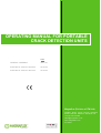
1
OPERATING MANUAL FOR PORTABLE
CRACK DETECTION UNITS
P920
GENERAL ASSEMBLY
15071.A1
ELECTRICAL CIRCUIT 220/240V
23130.A3
ELECTRICAL CIRCUIT 380/415V
23129.A3
Magnaflux (Division of ITW Ltd)
Faraday Road, South Dorcan Industrial
Estate, Swindon, Wiltshire, SN3 5HE, UK
+44 (0)1793 524566
[email protected]
www.magnaflux.com
01/12/2011
OPERATING MANUAL FOR PORTABLES
CONTENTS
Introduction
1
Safety precautions
2
Installation
3
Identification of controls
4
Operation of unit
5
Servicing
6
Trouble shooting
7
Service and calibration
8
Spares list
9
OPERATING MANUAL FOR PORTABLES
SECTION 1
INTRODUCTION
MAGNAFLUX is a division of ITW Ltd., a subsidiary of Illinois Tool Works
Incorporate of Chicago U.S.A. Magnaflux of Chicago, U.S.A. is also a
member of ITW Group.
MAGNAFLUX design and manufacture Non-Destructive Testing Equipment,
Fluorescent Penetrants, Contrast Penetrants and Magnetic Particle Materials
in its 3500 square metre facility.
MAGNAFLUX have over 50 years experience in the manufacture of NonDestructive equipment and materials.
Our design team consider the equipment and materials described in this
Manual to be the most practical for the inspection of your components, based
on the information received.
The design will ensure reliable results and durability, with minimum down time
for service, thus giving a maximum return on your investments.
The equipment is built in accordance with good machine tool standards and
all components used will be entirely suited for their intended use. The
equipment is built to MAGNAFLUX standards and practices.
MAGNAFLUX is approved to ISO 9001.
OPERATING MANUAL FOR PORTABLES
SECTION 1
Magnaflux Warranty Agreement
Your new Magnaflux product, when properly
used, maintained and serviced should give
years of excellent service.
Magnaflux guarantees that its products will be
free
from
defects
in
materials
and
workmanship for a period of 12 months from
the date of invoice. This Magnaflux warranty
covers only those defects which arise as a
result of normal use of the product and not
apply if the item has had :a)
Improper or inadequate maintenance.
b)
Misuse or unauthorised modification.
c)
Operation outside
capabilities.
the
products
design
This guarantee is in addition to and does not
reduce your minimum statutory rights.
OPERATING MANUAL FOR PORTABLES
SECTION 2
SAFETY PRECAUTIONS
In the interests of operator safety, the following points should be noted: DO NOT SMOKE WHILE PERFORMING NDT
Read thoroughly the instructions given with the chemicals to be used and
obey any warnings given
Ensure that the equipment has a good ‘earth’ connection before first
operation
Wear safety glasses when operating the unit
Never use the 108mm2 cable with damaged sheath exposing the wire
Always isolate the unit before removing the cover for any reason
Always use a good proprietary barrier cream on the hands to minimise skin
irritation. The wearing of gloves is not recommended
If the unit is protected by an earth leakage circuit breaker, check its
operation by pressing the test button
If an ultra violet lamp is used, be sure that:The filter glass is in place and is not cracked or damaged such that white light
is emitted.
After prolonged running the lamp housing gets very hot and can cause burning.
Do not touch this lamp housing with unprotected flesh. The MAGNAFLUX
Cool Running ZB100F reduces this risk.
Do not, under any circumstances, shine the ultra-violet light into eyes.
Direct viewing of the lamp may with certain people, cause irritation of the eye
known as ‘Fluorescence of the retina’.
Always wear UV absorbing spectacles.
OPERATING MANUAL FOR PORTABLES
SECTION 2
FIRE RISK
Kerosene based carriers pose a very low risk under normal
working conditions, however, kerosene will burn when subjected to
sufficient heat such as may be generated by an electric arc.
For this reason the following precautions are strongly advised: Do not use badly worn or pitted pistol prods
Check that firm contact is made with the Component under test
before initiating current flow
Use a high-flash-point kerosene such as MAGNAFLUX Carrier II
MAGNETIC FIELD RISK
Persons susceptible to strong magnetic fields, including those with
Pacemakers, are advised not to use or approach this equipment without
seeking professional advice.
AUDIBLE NOISE
Unlikely to exceed 70dB(A) under normal operating conditions.
OPERATING MANUAL FOR PORTABLES
SECTION 3
INSTALLATION
INSTALLATION SHOULD ONLY BE CARRIED OUT BY SUITABLE
QUALIFIED PERSONNEL.
These items of equipment are intermittently rated with a duty cycle of 10%
e.g. 2 seconds on 20 seconds off, at maximum output.
Model
Number
Magnetising Maximum
Current
Intermittent
Output
Output into
9mx108mm2
Cable
P920
AC/HWDC
1500A
Open
Control Current
Circuit Switch Drain
Output Voltage from
Voltage
supply at
Maximum
Output
Current
5
12V DC 55A
@
240v
30A
@
415v
External
Fuse
Required
25A
16A
AC current in RMS values
HWDC current in MAGAMP values = 2 x MEAN VALUE
THE MAXIMUM OUTPUT CURRENTS MUST NOT BE EXCEEDED.
NOTE:
a)
USING A CABLE LENGTH LESS THAN RECOMMENDED
IS LIKELY TO CAUSE THE UNIT TO EXCEED THESE
FIGURES, AND POSSIBLE DAMAGE.
Connect the integral lead of the P920 unit to a suitable electrical
supply, see above for maximum current draw.
Ensure the unit is PROPERLY ELECTRICALLY EARTHED.
NOTE:
b)
To comply with BS6072 the unit should be protected by an earth
leakage circuit breaker.
Connect output cables to appropriate outlets at front of unit by pushing
on and twist locking. Always utilise the ‘common’.
OPERATING MANUAL FOR PORTABLES
SECTION 4
IDENTIFICATION OF CONTROLS
All controls are situated on the front panel
Switches
S1 - Selector Switch - Labelled AC / DC
Function - This switch matches the ammeter to the output current
selected (by choice of output connector)
RV1 - Potentiometer - Labelled Min 1 - 9 Max
Function - Controls the current level
Lamps
LP1 - Lamp - Labelled ‘Mains On’ colour White
Function - Signifies mains power to unit
Meter
A moving coil meter is fitted to provide measurement of both AC and
HWDC currents.
AC current is calibrated in RMS (root mean square)
HWDC current is calibrated in Magamps (twice mean)
Both output currents are modified by the meter board which provides
the means of calibration.
Sockets
SKT1 - This socket provides an inlet for the remote control lead for
either the pistol grip prods or hand held push button
OPERATING MANUAL FOR PORTABLES
SECTION 5
OPERATION OF UNIT
Check that the circuit breaker, on the side of the filter unit, is OFF
Switch on the unit from customer’s supplied isolator
The P920 ‘Mains On’ light will illuminate when circuit breaker is
switched ON
Prod Magnetisation
Recommended cable lengths : 4.5 metres
Attach two lengths of 108mm2 cable with either end to the
common and AC or DC outlet located on the front panel. A prod
unit should be attached to the other end of the cables.
Plug the control cable of the prod unit into the SK1 socket
Turn the current control Potentiometer to the required position.
(Refer to NDT specifications for required values or British
Standard BS0672. Experience will then dictate values required for
standard parts.)
Make prod contacts with a clean surface of the component. Place
the prod tips approximately 150-200 mm apart on either side of
the suspected defect. Press the prod handle switch to energise
the unit and cause current to flow to the prod tips. The ammeter
will indicate the magnetising current.
Apply MAGNAFLUX dry powders using a dispenser, or spray on
MAGNAVIS/MAGNAGLO ink while the magnetising current is
flowing
Release the prod switch to stop the magnetising current and
remove the prods from the component
Inspect the area for indications of defects using visible light for
MAGNAVIS product or UV light for MAGNAGLO product
NOTE: The prod method can be utilised with clamps or leeches, but
it is necessary to substitute the hand held push button for the missing
trigger switch on the Prod assembly.
OPERATING MANUAL FOR PORTABLES
SECTION 5
Coil Magnetisation
Wrap a minimum of three turns of 108mm2 cable around or
through the component to be inspected. Plug the ends into the
common and AC or DC outlets.
Plug the hand held push button (remote control lead) into SKT1
Turn current control Potentiometer to required position
Refer to NDT Specifications for required values or British
Standard BS6072. Experience will then dictate values required
for standard parts.
Press the hand held push button to energise the unit and cause
current to flow. The ammeter will indicate the magnetising
current. The current x number of turns = Ampere turns.
Apply MAGNAFLUX dry powders using a dispenser, or spray on
MAGNAVIS/MAGNAGLO ink while the magnetising current is
flowing
Release the hand held switch to stop the magnetising current
Inspect the area for indications of defects using visible light for
MAGNAVIS product or UV light for MAGNAGLO product.
NOTE :
If the wrap-round coil method is used it is possible to only
magnetise in short lengths, for long components the coil will
need to be spaced along the component, magnetising and
inspecting for defects at each spacing.
OPERATING MANUAL FOR PORTABLES
SECTION 5
Demagnetisation
Use the wrap around coil as before during coil magnetisation but
this time only connect to the common and AC terminals.
Plug the hand held push button (remote control lead) into SKT1.
Turn current control Potentiometer to required position.
Refer to NDT Specifications for required values or British
Standard BS6072. Experience will then dictate values required
for standard parts.
Press the hand held push button to energise the unit and cause
current to flow. The ammeter will indicate the magnetising
current. The current x number of turns = Ampere turns.
Press the hand held button and whilst the current is flowing,
slowly separate the component from the coil by a minimum of 1
metre.
Check the residual magnetism using a MAGNAFLUX Field
Indicator Part Number 008M001 or 008M002.
OPERATING MANUAL FOR PORTABLES
SECTION 6
SERVICING
THE FOLLOWING MUST ONLY BE CARRIED OUT BY SUITABLE
QUALIFIED PERSONNEL.
General
The design of the equipment is such that only minimum of servicing is
necessary. The frequency of servicing is dependent upon the nature and
extent of work carried out. Obviously, if the equipment is engaged in the
inspection of machined parts it will require less maintenance than if used for
the inspection of rough castings, etc. Therefore, only an arbitrary guide is
given for the intervals at which different items of the equipment are to be
serviced.
Inspection and Preventative Maintenance
The following paragraphs describe the inspection and maintenance
procedures for the unit. These instructions include periodic lubrication,
inspection and cleaning, and the preservation of metal parts. Periodic
replacement of assemblies or components as a preventative measure is not
required.
SILICON CONTROLLED RECTIFIER ASSEMBLY CLEANING. The silicon
controlled rectifier assembly will gradually become coated with an
accumulation of dirt and other airborne materials. As this coating builds up,
the cooling effect of the rectifier assembly fans is reduced, and eventually the
scr’s overheat. Inspect rectifier assembly every six months for accumulation
of deposits. If the coating is excessive, clean the heatsink with compressed
air at 25 to 40 psi and a soft brush.
CAUTION:
Do not clean the rectifier assembly with a cleaning fluid.
GENERAL CLEANING. To prevent the excessive accumulation of dust and
dirt as well as other such contaminants, thoroughly clean the equipment as
required. No special cleaning procedures are required. However, a thorough
cleaning in accordance with the following procedures is required to assure
trouble free operation.
WARNING: Use cleaning solvents in a well ventilated room. Avoid breathing
the fumes and excessive skin contact with the solvents away
from an open flame. When using compressed air, do not direct
the air stream against skin.
OPERATING MANUAL FOR PORTABLES
1.
Electrical Parts. Minor cleaning, such as removal of dust and loose
foreign particles can be accomplished by using a soft brush or lint-free
cloth or by blowing out the dirt with dry compressed air at 25 to 40 psi.
When using an air jet to blow off dirt and dust, either avoid or be careful
when directing the air stream on delicate parts. To remove dirt, grease
or oil from electrical parts, use isopropyl alcohol and apply with a soft
brush. For best results, the cleaning agent should be applied at room
temperature. It may be necessary to brush some parts vigorously with
a stiff brush to remove hardened dirt particles. If possible, avoid
excessive use of cleaning solvent on electrical insulating materials.
After cleaning allow the cleaned parts to dry at room temperature for 10
to 15 minutes before operating the equipment.
2.
Mechanical Parts. Clean mechanical parts by first removing dust and
loose dirt particles with a brush, lint-free cloth or compressed air at 25
to 40 psi. Any accumulated dirt, grease or oil deposits that require
further cleaning may be removed with a bristle brush or cloth
moistened with a suitable solvent. After cleaning, allow the cleaned
parts to dry at room temperature for 10 to 15 minutes before operating
the equipment.
INSPECTION.
General
Where there are no established wear limits, perform a visual inspection to
locate worn and damaged parts which could cause improper functioning. It is
recommended that mechanical and electrical inspection be performed on the
assembled or partially disassembled equipment to determine the extent of
disassembly required. In the absence of any special inspection requirements,
operational tests are the most effective in isolating parts and assemblies
requiring further inspection.
1.
Check all wiring for discoloration, burnt insulation, breaks and security
of connections.
2.
Check the transformers for either an excessive wax deposit on the
surface, discoloration, or a pungent odour, or the presence of phenolic
resin. If in doubt the transformers must be checked by a Qualified
Engineer.
3.
Check terminal boards for broken or missing terminals and stripped
threads. Check tightness of connections.
4.
Check contactor contacts to determine whether silver has been worn
away.
The contacts are usable even though pitted, burnt or
discoloured. They should be replaced only if the silver surface material
has been torn away or completely worn off. The contacts are not to be
dressed or filled in any way.
OPERATING MANUAL FOR PORTABLES
NOTE:
Contact inspection necessitates removal of the contactor arc
hood cover.
5.
Depress and release contactor and relay armature and check for free
operation with no binding. Depressing the armatures will require
slightly more force since they operate against spring action to their
normally-open or normally-closed positions.
6.
Check the bus bars connections for tightness. Arcing and burn marks
between mating bus bars indicates a loose connection.
7.
Turn the cooling fan and check for free operation. The fan motor is
permanently self-lubricated.
Excessive binding necessitates
replacement. Check the motor housing and fan blade for a dust and
dirt build up. Use standard cleaning procedures and clean as require.
8.
Check the “eitherend-connector” for discolouring, burn marks or splits.
Replace them if damaged. Keep them clean for good contact.
9.
Check the 108mm2 cables for splits and exposed wires. Repair with
appropriate heat-shrink sleeving.
10.
Inspect the Black Light assembly for missing of broken filter or lamp
and the electrical leads for abraided or frayed insulation. Do not use
electrical insulating tape to repair electrical leads but have them
properly repaired or replaced.
11.
Check lamps and meter for broken lenses and / or burned out bulb.
Check all push button, toggle and selector switches for smooth and
proper operation as appropriate. Operate the CURRENT CONTROL
switch throughout its complete travel and check for smooth operation
with no binding or erratic operation; check the control travel and
function throughout its complete travel from minimum (off or 0) to
maximum.
12.
It is a legal requirement in many countries that the Electrical
Safety of equipment is checked periodically, commensurate with
use, but at least once each year. The basic tests required are to
check the condition of effectiveness of the electrical Insulation
and the continuity of the Protective conductor (earth).
WARNING:
DO NOT REPLACE ANY PARTS WITH OTHER THAN THOSE
RECOMMENDED BY MAGNAFLUX.
OPERATING MANUAL FOR PORTABLES
SECTION 7
TROUBLE SHOOTING GUIDE
THE FOLLOWING CHECKS SHOULD ONLY BE CARRIED OUT BY
SUITABLE QUALIFIED PERSONNEL.
Minor problem check list.
a)
Check the electrical supply and that the ‘Mains ON’ lamp is lit.
b)
Check the unit has not been overloaded and tripped out.
c)
Check for loose eitherend connectors.
d)
Check condition of prod tips.
e)
Check the P920 circuit board assembly by substituting a known
working board.
If a major fault occurs return to MAGNAFLUX for service and repair.
OPERATING MANUAL FOR PORTABLES
SECTION 8
SERVICE & CALIBRATION
Manufacturers are being increasingly faced with demands by customers for
certification relating to the conformance of their products to a specification.
NDT products are no exception and require application of accurate
measurements during manufacture in order to demonstrate assurance of
conformance.
The need for this assurance generally requires the
manufacturer to process equipment that is capable of an accuracy higher than
achieved in the product being certified.
It is a legal requirement in many countries that the Electrical Safety of
equipment is checked periodically, commensurate with use, but at least
once each year. The basic tests required are to check the condition and
effectiveness of the electrical Insulation and the continuity of the
Protective conductor (earth).
At MAGNAFLUX all our calibration equipment is tested and certified traceable
to national standards.
The department brings together the technical
expertise, experience and calibration facilities typical of the market leader in
NDT.
OPERATING MANUAL FOR PORTABLES
SECTION 9
Set of Recommended Spare Parts Holding for Two Years
Part No:
Description
P920
002D045
Diode
3
001F062
Fuse 1A
2
009P040
Potentiometer
1
015S117
Switch AC / DC
1
13092 A3
Meter Board Assy.
1
15027 A3
Eitherend Connector
3
Prods & Cables
015S178
Prod Switch
1
025T008
Prod Tip, Mild Steel
4
1238
Eitherend connector
3