1
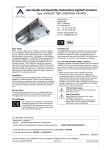
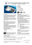
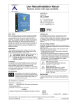
User Guide and Assembly Instructions AGRIBOX
Type: Agribox Small - Agribox Medium - Agribox X
AGRILIGHT b.v.
Vlotlaan 560,
2681 TX Monster
The Netherlands
Tel: +31 (0)174.287.287
Fax: +31 (0)174.287.292
Internet: www.agrilight.com
E-mail: [email protected]
IP65
Dear Client
Intended use
Firstly, we wish to thank you for choosing an Agrilight BV product.
The Agriboxes are specially designed for switching lighting on and
off in livestock pens. Agriboxes are durable and require very little
maintenance. These instructions provide the necessary information
for handling and installing your Agriboxes safely and correctly. We
therefore recommend that you read the instructions carefully and
keep them is a safe place.
In the event of doubt, please do not hesitate to contact your service
technician or Agrilight BV for additional information.
The Agribox is intended for the optimum control of lighting in
livestock pens. Any other use is not in compliance with the
intended use. Agrilight b.v. accepts no liability for damage or injury
resulting from any use of the Agribox other than its intended use,
i.e. for which it was developed and designed.
Application
The Agribox constitutes part of the Agrilight range of products for
the livestock industry and is designed for producing optimum
lighting conditions in livestock pens (for beef-cattle, dairy-cattle).
Installation
It is important to note that the Agribox should be installed by a
certified technician. If this is not done, the product warranty will be
invalid.
In compliance with the instructions for installation laid down by
Agilight BV, all generally and locally applicable building and
construction regulations should be respected and complied with.
For your safety. Caution!
Agrilight BV attaches the utmost importance to the fact that the
Agribox is operated and maintained in a manner that ensures the
safety of the user.
Please follow the instructions below in order to ensure the safe
and reliable operation of the Agribox:
1. Always read the user and instruction manual of the Agribox
before installing.
2. Ensure that the persons responsible for installing and mounting/
connecting the Agribox are familiar with the instructions and all
other relevant information contained in the manuals before
installing.
Please ensure before installing that all instructions are fully
understood. This is the responsibility of the certified technician
responsible for installing the Agribox.
230V AC Power supply
Components in de Agribox are connected to a
power supply of 230V.
Service parts
To ensure proper operation of the unit, only original Agrilight BV
components should be used, or components of the same quality.
Safety instructions
Always follow and comply with the safety
instructions of this manual.
If the safety instructions and warnings are not
complied with, this may damage the installation
and/or lead to serious personal injury or death.
CE certification
With reference to the conformance certificate for
the Agribox, the CE mark on the type label of the
Agribox indicates that the product is in full
compliance with EU consumer safety, health and
environmental requirements.
EU declaration of Conformity:
Manufacturer: Agrilight b.v.
Address:
Vlotlaan 560, 2681 TX Monster, Netherlands
Hereby certifies that the Agribox with type designation:
Agribox Small (single phase 20A 230V ~ 50Hz)
Agribox Medium and Agribox X (3 phase 20A 400V ~ 50Hz)
complies with European harmonized standards:
Safety requirements for electricalequipment measurment, control and laboratory us norm EN61010-1
EMC compliance accordance with standards:
EN55015, EN61547:1995 incl. amedent A1:2000, EN61000-6-2 and EN6100-6-3:2007
The Agribox complies with the IP65 standard if the connecting glands have been properly tightened by the user.
Monster, 2010
Agrilight b.v.
We retain the right to make amendments to the text, drawings and diagrams without any prior notification.
Document : Agribox GB
Version: 01
Date: May 2010
1
Unpacking and Inspecting
1. Carefully unpack the Agribox.
2. Inspect the contents of the package for any damage that may have occurred during transport.
3. In the event of damage, contact Agilight BV immediately, with reference to the packaging documents. You are advised to discontinue
the installation of the Agribox in the event of damage, even if the damage in question appears to be superficial or minor.
In the event of damage, please consult Agrilight BV first, before you consider installing the Agribox.
Introduction and scope of delivery
The Agribox line is a range of control cabinets for connecting and controlling various types of AL2007 armature supplied by Agrilight.
The cabinet has an IP65 value, which means that the cabinet is completely dust-free and spraywater-tight in all directions, provided that
all connecting glands and covers are properly tightened and secured and the protection cover is closed.
Number
No.
[1]
[2]
[3]
[4]
[5]
[6]
[7]
[8]
[9]
[10]
[11]
[12]
Description
Model
Agribox
Feed-through sleeve (are not used)
Keys/spanners
Screw
Cable ties
Sealing caps
Trims/covering strips
Feed-through plug (not used)
Klemko twilight sensor, fixtures and manual in packaging
Moeller ETR2 (timer) manual
Moeller Z-SDM\1KWO (timer clock) manual
Moeller PLC ME Easy manual
Agribox Manual (not shown)
[4]
[2]
Small
Medium
X
1x
4x
2x
1x
2x
4x
1x
1x
1x
1x
1x
-1x
1x
4x
2x
1x
2x
4x
1x
1x
2x
--1x
1x
1x
-----------1x
[6]
[3]
[10]
[8]
[5]
[9]
[7]
[11]
[12]
[1]
[1]
[1]
TYPE: Agribox Small
TYPE: Agribox Medium
TYPE: Agribox X
The daylight function of the armatures can
be switched on and off both manually and
automatically with the timer and twilight
control via the Agribox Small.
Night-lighting can also be switched on and
off manually via the Agribox Small.
The daylight function of the armatures can
be switched on and off both manually and
automatically with the timer and twilight
control via the Agribox Medium. Night-lighting
can also be switched on and off manually
and automatically via the Agribox Medium.
The Agribox X is a slave model and can be
connected to the Agribox Medium in order
to extend the capacity of the Agribox
Medium with two additional electrical
groups.
Technische gegevens
Specifications
AGRIBOX
Model
Small
Medium
X
Dimensions
Weight (complete)
Max. Light load
Max. C load
Max. Load Night-lighting
Max. power supply.
400x320x125
3.35 Kg
2x6x250W of 2x4x400W *
470uF/Phased
900W
230V/50Hz/20Amax
(1 Phase / N / PE)
400x320x125
4.00 Kg
2x18x250W of 2x12x400W *
470uF/Phased
900W
400V/50Hz/25Amax
(3 Phase / N / PE)
270x180x170
3.30 Kg
2x18x250W of 2x12x400W *
470uF/Phased
-400V/50Hz/25Amax
(3 Phase / N / PE)
* armature type: AL2007 (lamp type: High pressure sodium (HPS) of Metallic Halide (MH)
2
Installation
If the following instructions and safety
warnings are not complied with, this may
result in damage to the unit, serious personal
injury or death.
•
•
•
•
•
The Agribox may only be installed by a certified technician.
Always block off any traffic in the vicinity where the Agribox is
being installed before commencing with any work on the
installation.
Always turn off the power to the Agribox before opening the
cabinet or carrying out service or maintenance on the Agribox.
Ensure that the power supply is not turned on accidentally. To
do this, a lock can be mounted to the red/yellow coloured main
switch.
Keep the direct vicinity free from animals and any internal
transport whilst carrying out installation activities.
Only use electrically insulated tools!
•
Ensure that you do not confuse the phase, earth and
null connections when connecting - this may result in
life-threatening situations!
•
Ensure that the power supply and voltage corresponds
to the power supply and voltage required by the Agribox.
These are clearly indicated on the cabinet sticker.
•
When connecting up, consult the circuit diagram in this
manual and always ensure that you comply with the
legally applicable connecting requirements (e.g. NEN 1010
for the Netherlands).
.The lighting plan shows the conditions that must be taken into
account when installing. These instructions must be fully complied
with in order to ensure uniformity and a proper light level.
Agrilight BV cannot be held liable for damage
andor injury resulting from improper mounting
and installation.
Mounting the cabinet to the wall
[6]
[6]
[6]
[6]
1. Remove the cover by unscrewing the 4
2. 2. Mount the cabinet to the wall with 4 screws, preferably in the corners. If the user
screws on the front of the cabinet with a
chooses to mount the unit by screwing to the base plate, the sealing caps [6] included in
1.6 x 9 mm screwdriver.
the package must be used in order to ensure that the unit is water-tight.
Connecting power
Disconnect the power supply before you connect the Agribox!
Ensure that the power supply cannot be switched on accidentally whilst connecting the unit!
3. Feed the cables/leads through the glands into the cabinet and connect these according to the circuit diagram - see pages 6-8.
B2
A
B
C
A B1
C
D
A
B
C
D
TYPE: Agribox Small
TYPE: Agribox Medium
TYPE: Agribox X
A = power supply
B = Klemko twilight sensor
C = Armatures
A = power supply
B1/2 = Klemko twilight sensor
C = Armatures Group 1
D = Armatures Group 2
A = power supply
B = Connecting lead Agribox Medium
C = Armature Group 1
D = Armature Group 2
Gland feed-throughs: diam. of leads min. 11 mm, max. 14 mm.
3
Operation
Main switch
The main switch is intended for switching the Agribox unit on and off and not for switching the lighting in
the livestock pens on and off. When in use, always leave the main switch in the I (“ON”) position.
1. Position 1 (“ON”) = Agribox switched on.
2. Position O (“OFF”) = Agribox switched off.
The main switch can be locked.
Always switch the main switch off (O = “OFF”) before commencing with service or
maintenance activities on the Agribox or lighting installation.
Always lock or secure the main switch, for example with the use of a padlock, to ensure
that it cannot be switched on unintentionally!
Selector switches
Agribox Small
Agribox Medium
A
B
A
B
A = Day – Off – Night switch
B = On – Off – Auto switch
A = On – Auto – Off – Night switch
B = On – Off – Auto switch group 1 (Day 1)
C = On – Off – Auto switch group 2 (Day 2)
Auto-switching
Auto-switching ‘Daytime lighting’
(preferred setting)
In order for the cabinet to operate automatically, the selector
switch must be set to the “On-Off-Auto” “Auto” position.
The timer clock switches the lighting automatically in conjunction
with the Klemko twilight sensor.
Caution: When operating in Autoswitch mode, the
“Day-Off-Night” switch must always be in the “Off”
position.
Manual Switching
In order for the cabinet to be operated manually, the selector
switch must be set to the “On-Off-Auto” “On” position.
The “Day-Off-Night” button can then be used for manual
switching:
• Day: daytime lighting ON
• Off:
all lights OFF
• Night: night lighting ON
When the switch is set manually to the “On-Off-Auto” “Off”
position, all lights will switch off.
The night-lighting does not switch on/off automatically; it must
be switched on/off manually using the Day-Night switch.
Caution: When the switch is set to manual, there
must be a delay of 10 minutes between switching
off and switching on again. This is to prevent
permanent damage to the lights if they were to be
switched on within a 10 minute period.
C
Set groups 1 and 2 to “AUTO”
Daytime lighting of group 1 will switch on after the set value of
twilight sensor 1 has been reached.
Daytime lighting of group 2 will switch on after the set value of
twilight sensor 2 has been reached.
Manually switching ‘Daytime Lighting”
Set the switch of one of the desired groups 1 or 2 to the “ON”
position.
Group 1 will switch on immediately and if groups 1 and 2 are
switched on together, group 2 will come on after a short delay of
50 seconds.
Caution: After switching a group off and immediately
on again, there will be a pre-programmed delay of 10
minutes before the daytime lighting turns on again.
This is to prevent damage to the lights.
Auto-switching “Night Lighting”
Set Night-Switch manually to the “Auto” position.
Caution: In AgriLED armatures, there is a delay of 10
minutes when switching between night-time lighting
and day-time lighting.
Manually switching ‘Night Lighting”
Set Night-Switch manually to the “On” position. The nightlighting will now switch on immediately. The night-lighting can
be switched off again by turning the switch to the “Off”
position.
Attention when using AgriLED armatures: if the unit is
switched on shortly after the day-time lighting has
illuminated, there will be an automatic delay of 10
minutes before the night-lighting is activated.
Attention: After switching on the night-lighting manually,
this can be turned off again when leaving the livestock
enclosure by setting the Night switch to the “Auto” or
“Off” position.
4
AgriLED Red© Armatures
Application of AgriLED Red©
The cabinet is connected as standard for use with AgriLED Red© armatures, including red
LED night-lighting. This includes a delay set to 10 minutes between switching the nightlighting on and off to prevent damage to the LEDs.
The display shows “Int. Night”.
No AgriLED Red©
If another type of armature is used for the night-lighting
(e.g. PL or TL fluorescent tube light armatures), then the
night-lighting can be switched on and off automatically
using clock time settings.
This can be changed by removing the grey wire
between terminal 2 on the terminal strip and the PLC
input 3 (I3).
‘Ext. Night” is now displayed on the PLC.
The night-lighting now switches on and off immediately at the preset time (night-time).
However, the daytime lighting will be switched on in the morning with a short delay of
10 minutes if the twilight sensor(s) is/ are switched on.
If the AgriBox M is set to Ext. Night with the AgriLED Red©
armatures connected, then the warranty on the armatures is no
longer valid!
Settings
[B]
Klemko settings
Setting the luminance level
The amount of light detected by the Klemko twilight sensor
can be set by turning the [A] button on the front.
Turning the button towards the sun pictogram increases the
sensitivity of the sensor.
Turning the button towards the moon pictogram decreases
the sensitivity of the sensor.
The twilight sensor is activated as soon as the red LED [B]
lights up.
Timer ETR2-11 (Agribox Small)
There must be a minimum of 10 minutes between switching
the lights off and on again. This is to prevent permanent
damage to the lights.
The Moeller ETR2-11 timer was set in the factory
and may NOT be modified. If this is done, this will
invalidate the warranty.
Timer Z-SDM/1KWO (Agribox Small)
Refer to Moeller Z-SDM/1KWO manual shipped with the
Agribox Small.
Timer of PLC (Agribox Medium)
The Klemko twilight sensor will activate after 10 minutes. The
lights will be activated as soon as the ambient light level is less
than the desired setting (if the switch is on automatic).
5
PLC (Agribox Medium)
PLC Settings
No changes or modifications may be made to software - this renders the warranty invalid. Any changes
made to the software can be read out, i.e. made
visible if any changes have been made. The settings
below do not fall under the above-mentioned software
restrictions and may be set as desired.
Clock program
The PLC has 3 pre-programmed clock programs
The fourth clock program can be freely programmed.
Options include:
Pr. 00000 = Clock program 1:
turn on lighting at 05:00 hrs, switch off at 21:00 hrs
Pr. 00001 = Clock program 2:
turn on lighting at 6.00 hrs, switch off at 22.00 hrs
Pr. 00002 = Clock program 3:
turn on lighting at 7.00 hrs, switch off at 23.00 hrs
Pr. 00003 = Clock program 4:
clock can be programmed as desired
[standard at 06:00 hrs-22:00 hrs].
These clock programs can be used to set seasonal lighting
parameters.
Selecting clock program
1. Press the arrow
and keep pressed for 10 seconds.
2. Then press the arrow
or
and keep pressed until the
correct program is selected.
1.
2.
3.
4.
5.
6.
7.
8.
9.
Display
Delete
-- (no function)
Back (Escape)
Confirming opening menu and changing value parameters
Move cursor to increase value parameter
Move cursor to decrease value parameter
Scrolling back through parameter menu
Scrolling forwards through parameter menu
Setting Time and Date
1.
2.
3.
4.
5.
6.
7.
8.
9.
10.
11.
12.
13.
14.
15.
16.
17.
18.
Press button
Press arrow
to select ‘Set Clock’
Press button
Press button
again
Press button
again
Set hours using arrow
(+ 1 hour) and
(-1 hour)
After setting the desired hour, press button
to set
minutes
Press (+1 min.) arrow
and
(-1 min.) to set minutes
Press button the time is now set
Press arrow
to set date
Press button
Set the day parameter by using the arrow
(+1 day)
and
(-1 day)
After setting the day parameter, use the arrow
to set the
month
Set the month parameter by using the arrow
(+1 month)
and
(-1 month).
Press button
Press the arrow
to set the year
Press button
Set the year parameter by using the arrow
(+1 year)
and
(-1 year)
19. Press button
To leave the menu, keep pressing the button
until Agrilight is displayed.
6
Changing clock times to set new time in clock program 4.
1. Press
2. Press arrow
and select parameter
3. Press
4. Select clock 4
5. Press arrow or to select days, hours and minutes
6. Press
to changes settings
7. Press
or
to make changes
8. Press
to confirm changes
9. Press
to return to the previous menu
Operating hours counter
Press arrow
to view operating hours. The unit automatically
displays the number of operating hours of Group 1, Group 2 and
the night lighting.
After 30 secs. the display will automatically return to the main
menu.
Safeguarding program
When switched on for the first time, it will take 10 minutes
before the day-lighting can be switched on.
If the lights are on, the day-lighting can be switched off
manually.
In emergency situations, always disconnect the unit from the
power supply by using the yellow-red main switch.
Electrical control circuit Agribox Small
Main circuit
L1
L1
2
Load
X1 N
L
Klemko
=Auto
S2-1
=Hand
S2-2
N
3
delay 10 min
15
N
1.1
I1
A
U1
Clock
Night
S1-2
2
3
-X1
Pe
T1
T2
T3
1
-X1
3
-X1
A02
-X1
N
4
5
I1
K1
F1
Fuse 6.3A
Nightlight
N
2
A01
L1
L2
L3
A02
K1
Day
1 S1-1
B
A01
18
H1 F
1.1
L1
X1 L1
-X1
1
2
Daylight
Pe
1
2
Connections of clamping rail and twilight sensor
Line out
Clamp
no.
Designation on
sticker in cabinet
Description
PE
N
L1
PE
1
2
3
4
5
6
PE
Line in PE
Line in N
Line in L
PE Line out
Klemko Load
Klemko out L
Klemko out N
Line out N
Night N
Night L
Night PE
Earth connection input
Null [neutral] connection input
Phase input
Earth connection input
Dimmer sensor output ‘load’
Power supply twilight sensor ‘Phase’
Power supply twilight sensor ‘Null’
Null [neutral] connection output
Night-lighting Null
Night-lighting
Earth connection night-lighting
Connecting Klemko twilight sensor
• Connect clamp no. 1 of the Agribox Small to terminal
point L of the twilight sensor.
• Connect clamp no. 2 of the Agribox Small to terminal
point L of the twilight sensor.
• Connect clamp no. 3 of the Agribox Small to terminal
point N of the twilight sensor.
7
Electrical control circuit Agribox Medium
Main circuit
PLC-connections
Connections of clamping rail and twilight sensor
L1
L2
Group 1
Clamp no. Designation on cabinet label Description
L1
L2
L3
N
PE
PE
PE
1
2
3
4
5
6
7
8
9
10
PE
8
Line in L1
Line in L2
Line in L3
Line in N
Line in PE
PE Line out 1
PE Line out 2
Klemko-1 out L1
Klemko-2 out L1
Klemko-1 Load
Klemko-2 Load
Klemko-1 out N
Klemko-2 out N
Lamp N
Lamp N
Night N
Night L1
Night PE
Phase 1 input
Phase 2 input
Phase 3 input
Null [neutral] connection input
Earth connection input
Earth connection output Group 1
Earth connection output Group 2
Twilight Sensor 1 Phase
Twilight Sensor 2 Phase
Twilight Sensor 1 output ‘load’
Twilight Sensor 2 output ‘load’
Twilight Sensor 1 Null
Twilight Sensor 2 Null
Output Null group 1
Output Null group 2
Night-lighting Null
Night-lighting Phase 1
Earth connection night-lighting
L3
L1
L2
L3
Group 2
Connecting Agribox Medium to
Agribox X
Group 1
Connect relay A1 (group 1) relay of the Agribox X
to T1 of relay K1 (group 1) of the Agribox Medium.
Group 2
Connect relay A2 (group 2) relay of the Agribox X
to T1 of relay K2 (group 2) of the Agribox Medium.
Connecting Klemko twilight sensor
• Connect clamp no. 1 of the Agribox Medium to
terminal point L of the twilight sensor.
• Connect clamp no. 2 of the Agribox Medium to
terminal point L of the twilight sensor.
• Connect clamp no. 3 of the Agribox Medium to
terminal point N of the twilight sensor.
Electrical control circuit Agribox X
Main circuit
Connections of clamping rail
L1
L2
Group 1
Clamp
no.
Designation on
sticker in cabinet
Description
PE
N
L1
L2
L3
PE
PE
1
2
3
4
Line in PE
Line in N
Line in L1
Line in L2
Line in L3
PE Line out 1
PE Line out 2
Lamp N
Lamp N
Relay K1-A1
Relay K2-A2
Earth connection input
Null [neutral] connection input
Phase 1 input
Phase 2 input
Phase 3 input
Earth connection output Group 1
Earth connection output Group 2
Output Null group 1
Output Null group 2
Relay control Group 1 (Medium)
Relay control Group 2 (Medium)
L3
L1
L2
L3
Group 2
Connecting Agribox X to Agribox Medium
Group 1
Connect relay T1 of relay K1 (group 1) of the Agribox
Medium to relay A1 (group 1) of the Agribox X.
Group 2
Connect relay A2 (group 2) relay of the Agribox Medium
to relay A2 (group 2) of the Agribox X.
9
Maintenance
Disconnect the Agribox from the power
supply before performing maintenance on the
Agribox!
Agrilight BV recommends that you have your Agribox serviced
once a year by a certified technician to test operation and to
check all fixtures and connections.
In order to retain the amount of lighting, you are advised to check
the condition of the lights and the sensor and to clean the
armatures and the display of the twilight sensor.
Malfunctions
Control Cabinet/Lighting malfunctions:
• Check that the Agribox main switch is in the I (“ON”) position;
• If applicable: check that the Agribox X main switch is in the
I (“ON”) position;
• Check that the 3-way switch is not on the “OFF” position;
• Check that the display of the twilight sensor is not soiled or
dirty;
• Check that power supply fuses and/or ceramic fuses of the
Agribox;
• Ensure that there is a power supply available;
• Check and/or replace the light(s).
If the control still doesn’t operate correctly:
When checking malfunctions, be aware of the risk of
electrically live components. Although the Agribox is
designed with safety in mind and is earthed, hazards
due to malfunctions can never be excluded.
Only certified technicians are permitted to handle the
electrical installation or to perform measurements on
the unit.
Always disconnect the Agribox before opening the
plastic cover (turn the main switch and lock it).
Be aware of and prevent any accidental activation
by others or by an automated control and/or dimmer
switch. In the event of a malfunction, never touch
the Agribox whilst the power supply is still
connected or if the casing of the Agribox is damaged
or wet.
• Check the wiring in the control cabinet(s).
CONDITIONS OF WARRANTY
1. If it appears that your product does not function well, even though you have used it in the correct manner and in
accordance with the written user manual and assembly instructions, the product will be replaced free of charge within
a period of one year after purchase. In order to claim this warranty the customer must submit the product invoice to
Agrilight BV with the 1 year warranty period.
2. The product must be returned to Agrilight BV within 30 days following the occurrence of the defect or malfunction for
the purpose of verification.
3. The product must be provided with a project name and sent to the following address:
Agrilight b.v.
t.a.v. Service dept.
Vlotlaan 412
2681 TV Monster - The Netherlands
4. When Agrilight bv sends the replacement parts you will receive an invoice that will be credited to your account when
and if it can be verified that the malfunction of defect falls under the warranty.
5. If Agrilight BV has not received the defective product by return mail within 30 days of the invoice date, the warranty
invoice will be treated as a sales invoice after which period the invoiced amount must be paid to Agrilight BV within 30
days.
6. The warranty does not cover the following situations for which the customer will be invoiced during the warranty
period:
a. defects or damage resulting from fire, earthquakes, floods, lightning strikes, other natural disasters, as well as
environmental pollution and problems related to power supply.
b. Defects resulting from sand, mud, dirt etc. entering the cabinet of the product.
c. Defects resulting from transport, accidents, shock and vibrations etc. following the purchase from and delivery of
the product by Agrilight BV.
d. Defects resulting from negligence, carelessness or incorrect storage, improper maintenance etc.
e. Defects resulting from improper use (such as the use of the unit for purposes not listed in the user manual and/or
assembly instructions etc.).
f . Defects resulting from (uncertified) repairs and modifications.
g. If the invoice cannot be submitted together with the product when warranty claims are made.
h. If changes have been made to the original purchase invoice or to the customer name on the invoice.
7. The liability on the part of Agrilight BV is restricted to the scope of this warranty and only includes the replacement and/
or repair of the product. Agrilight BV accepts no liability for damages incurred directly or indirectly as a result of any
defects in the product. Agrilight BV is not liable for expenses incurred as a result of disassembly and assembly/
mounting, or expenses incurred as a result of travel and accommodation.
8. Any damage resulting from transport or incomplete delivery must be reported to Agrilight BV within 5 working days.
Any notifications received by Agrilight BV beyond this period do not fall within the scope of the warranty or warranty
period.
LIABILITY
Agrilight BV states emphatically that it cannot be held liable for damages of any kind or magnitude, caused by non-compliance
with the instruction in this manual or as a result of the non-compliance with the connecting and installing requirements
according to NEN 1010. We also refer to our terms and conditions of delivery according to the conditions and requirements laid
down by the Netherlands Metal Association and any additional warranty provisions of Agrilight BV.
All technical modifications reserved.