1
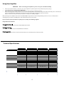
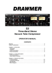
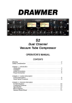
Rockerverb 50/100 MKII Owners Manual
Orange Amplifiers
OMEC House
108 Ripon Way
Borehamwood
Hertfordshire
WD6 2JA
ENGLAND
Tel: +44 20 8905 2828
Fax: +44 20 8905 2868
[email protected]
Orange USA
2065 Peachtree Industrial Ct.
Suite 208
Atlanta, GA 30341
USA
Tel: 1-404-303-8196
Fax: 1-404-303-7176
[email protected]
Before Operating Read These Important Safety Instructions
The exclamation point within
an equilateral triangle and
"WARNING" are intended to
alert the user to the presence
of important operating
instructions. Failure to heed
the instructions will result in
severe injury or death.
The lightning flash with
arrowhead symbol, within an
equilateral triangle, is
intended to alert the user to
the presence of uninsulated
‘dangerous voltage’ within the
product’s enclosure that may
be of sufficient magnitude to constitute a risk of
electric shock to persons. Terminals labeled as
“Speaker Outputs” must be connected to a speaker
cabinet of the designated load rating using an
un-shielded two conductor cable for speaker use at
all times during operation.
• Read these instructions.
• Keep these instructions.
• Heed all warnings.
• Follow all instructions.
• Do not use this apparatus near liquid.
• Clean only with dry cloth.
• Do not block any ventilation openings. Install
in accordance with the manufacturer’s instructions.
• Do not install near any heat sources such as
radiators, heat registers, stoves, or other apparatus
(including amplifiers) that produce heat.
• Do not defeat the safety purpose of the polarized
or grounding-type plug. A polarized plug has two
blades, one wider than the other. A grounding type
plug has two blades and a third grounding prong.
The wide blade or the third prong is provided for
your safety. If the provided plug does not fit into
your outlet, consult an electrician for replacement
of the obsolete outlet.
• Refer all servicing to qualified service personnel.
• Damage Requiring Service: Unplug this product
from the wall outlet and refer servicing to
qualified service personnel under the following
conditions: (a) When the power-supply cord or
plug is damaged; (b) If liquid has been spilled, or
objects have fallen into the product; (c) If the
product has been exposed to rain or water; (d) If
the product does not operate normally by
following the operating instructions. Adjust only
those controls that are covered by the operating
instructions. Improper adjustment of other controls
may result in damage and will often require
extensive work by a qualified technician to restore
the product to its normal operation; (e) If the
product has been dropped or damaged in any way;
(f ) When the product exhibits a distinct change in
performance - this indicates a need for service.
• Replacement Parts: When replacement parts
are required, be sure the service technician has
used replacement parts specified by the
manufacturer or have the same characteristics as
the original part. Unauthorized substitutions may
result in fire, electric shock, or other hazards.
• Servicing: Do not attempt to service this product
yourself as opening or removing covers may expose
you to dangerous voltage or other hazards.
This Orange Amplifier conforms to UL Standard 60065 for Audio, Video and Similar Electronic Apparatus - Safety Requirements;
Certified to CAN/CSA-C22.2 No. 60065-03; IEC 60065 2001 + A1:2005
This device complies with part 15 of the FCC Rules. Operation is subject to the following two conditions: (1) This device may not
cause harmful interference, and (2) this device must accept any interference received, including interference that may cause
undesired operation.
1
ROCKERVERB 50/100 MKII Owners Manual
Contents
Warnings ................................................................................................................................................................................................1
Introduction .........................................................................................................................................................................................2
Front and Rear Panel Explanations...............................................................................................................................................3
Using Your Amplifier ..........................................................................................................................................................................4
Warranty ................................................................................................................................................................................................5
Thank you for choosing Orange. You are now a member of the ‘Legendary British Guitar Amplifier’ owners club!
Since 1968, when the company was founded, Orange has been a pioneering force in the guitar amplification
industry. Today, with a team of the world’s finest amplifier engineers, Orange continues to push back the
boundaries of conventional tube amplifier design.
Our commitment to craftsmanship and quality control has allowed our amplifiers to stand the test of time, giving
their owners as much pleasure now, as the day they were bought. To maintain this level of excellence, each Orange
amplifier is put through many rigorous test procedures before leaving the factory.
The warmth, tonal quality and rich harmonics generated by a valve amplifier cannot be reproduced by ‘artificial’
means. Many guitarists have reached the same conclusion: neither the transistor nor microchip is a suitable
alternative to valve technology.
This booklet contains valuable technical and safety information Please take the time to read this manual as the
information may enhance the sound and performance of your amplifier.
We are confident that you will be delighted with your new purchase and that it will provide you with many years
of enjoyment.
2
Please ensure your amplifier is switched to the correct voltage for your country. If unsure please consult your dealer.
Front Panel
CLEAN CHANNEL
DIRTY CHANNEL
REVERB
POWER CHANNEL
1.
OFF
STANDBY
DIRTY
ON
CLEAN
1
2
3
VOLUME
4
5
TREBLE MIDDLE
6
7
BASS
GAIN
8
9
TREBLE MIDDLE
10
11
BASS
VOLUME
12
13
INPUT
14
Power/Standby Switch
Power up the amplifier by switching the power, off/standby/on switch to the standby position
and then switch to on, after 2 minutes.
Channel Switch
The channel, clean/dirty switch, switches from the clean channel to the dirty channel, when
there is no footswitch attached.
Power Indicator Lamp
Reverb Control
Controls the Reverb level for both channels
Volume Control
The volume control adjusts the output volume of the dirty channel.
High levels of volume will heavily overdrive the output stage!
Treble Control
The treble control adjusts the treble response of the dirty channel.
Middle Control
The middle control adjusts the midrange response of the dirty channel.
Bass Control
The bass control adjusts the bass response of the dirty channel.
Gain Control
The gain control adjusts the gain of the dirty channel. High levels of gain will heavily overdrive
the pre-amp and may sometimes be uncontrollable, especially when used at high volume
levels! This will be more apparent when used as a combo!
Treble Control
The treble control adjusts the treble response of the clean channel.
Note: When all three tone controls are set to zero, there will be no sound from
the clean channel!
Middle Control
The middle control adjusts midrange response of the clean channel.
Bass Control
The bass control adjusts the bass response of the clean channel.
Volume Control
The volume control adjusts the volume of the clean channel. High levels will overdrive the
output stage in a vintage manner!
Input Socket
For both channels
2.
3.
4.
5.
6.
7.
8.
9.
10.
11.
12.
13.
14.
Rear Panel
SWITCHES
SPEAKER OUTPUTS
8
8
16
RK100H
MK II
OUTPUT VALVE
SELECTION
3184582
ROCKERVERB 100 MKII
SEND
VALVES LEFT TO RIGHT FROM REAR
Preamp: Front Row:ECC83 (12AX7) ECC83 (12AX7) ECC83 (12AX7) ECC81 (12AT7)
Preamp: Rear Row:ECC81 (12AT7) ECC81 (12AT7) ECC83 (12AX7)
Output: EL34 x 4, 6CA7 X 4, KT88 X 4, 6550X 4, or 6L6GC X 4
1
1.
2
Send & Return Sockets
2.
Channel Footswitch Socket
3.
Reverb Footswitch Socket
4.
Speaker Outputs
5.
Output Valve Selector
6.
Mains Socket & Fuse Holder
7.
Mains Voltage Switch
8.
HT Fuse Holder
3
EL34
6CA7
KT88
6550
6L6GC
RETURN CHANNEL REVERB
4
4
4
AMPLIFIER HEAD
100 WATTS RMS
WARNING!
ALWAYS CONNECT AMPLIFIER
TO CORRECT SPEAKER LOAD
BEFORE POWERING UP
POWER RATING:
575 VA
ORANGE
LONDON ENGLAND
5
CAUTION
RISK OF ELECTRIC SHOCK
DO NOT OPEN
WARNING: TO REDUCE THE RISK OF FIRE OR ELECTRIC
SHOCK, THIS APPARATUS SHOULD NOT BE EXPOSED TO RAIN
OR MOISTURE AND OBJECTS FILLED WITH LIQUIDS SUCH AS
VASES, SHOULD NOT BE PLACED ON THIS APPARATUS.
TO PREVENT THE RISK OF FIRE HAZARD, REPLACE WITH
SAME TYPE 250 VOLT FUSE.
AVIS: DANS LE BUT DE REDUIRE LES RISQUES D’INCENDIE
OU DE DECHARGE ELECTRIQUE, CET APPREIL NE DOIT PAS
ETRE EXPOSE A LA PLUIE OU A L’HUMIDITE ET AUCUN OBJET
REMPLI DE LIQUIDE, TEL QU’UN VASE, NE DOIT ETRE POSE
SUR CELUI-CI. REMPLACER PAR UNFUSIBLE DE MEME TYPE
ET DE 250 VOLTS.
MAINS FUSE
220/230-240V:
T3.15A H
100/120V:
T6.3A H
RK100HMII-
6
50/60 Hz
VAC
7
HT FUSE
T1A H
8
The effects loop, send and return jack sockets (rear of amplifier) are intended for use with outboard
pedals or rack equipment such as delay, reverb and chorus etc. Effects such as wah wah, fuzz, distortion
etc, would probably be best placed between the guitar and amplifier input! The effects loop is wired in
series with the pre-amp signal and is completely valve driven!
The footswitch jack socket (rear of amplifier) enables channel switching using any latching footswitch.
Note: The footswitch will override the channel, clean/dirty switch.
Attaching an optional footswitch to this socket will allow you to remotely switch the reverb
effect on and off.
When using a single Orange 16 ohm speaker cabinet, (i.e. PPC412 or PPC212), attach it to the
16 ohm output socket on your amplifier. When using two Orange 16 ohm speaker cabinets attach each
one to a separate 8 ohm output socket on your amplifier.
When using a single 8 ohm cabinet attach it to either one of the two 8 ohm output sockets
on your amplifier.
WARNING: Never use two 8 ohm cabinets at the same time.
When using a Rockerverb 50 combo with a 16 ohm extension speaker, disconnect the internal
speaker from the 16 ohm socket and reconnect to one of the two 8 ohm sockets. Connect the
extension speaker to the other 8 ohm socket.
WARNING: Orange Rockerverb amplifiers should not be used with 4 ohm speakers.
Although both the Rockerverb 50 and 100 MKII come fitted and biased with
EL34’s, the output valve selection switch (rear of amplifier) allows for the use of other output valve types,
such as 6L6’s, 6550’s and KT88’s. Note: This switch only puts the amplifier bias in the region for the above
listed valve types! Fine bias tuning for the actual set of output valves to be fitted, needs to be performed
by a qualified service technician!
This is where your mains lead plugs in. Also the mains fuse is located here.
T2Amp 220/230-240 VAC (T5Amp 100/120 VAC) on 50 watt model.
T 3.15Amp 220/230-240 VAC (T6.3Amp 100/120 VAC on 100 watt model.
Switches amp between 220V and 240V or 100V and 120V. This should be set to the mains
electricity voltage used in the country where the amplifier is to be operated.
This is where your HT fuse is located.
2 x T500MA on 50 watt model.
1 x T1Amp on 100 watt model.
Please ensure your amplifier is switched to the correct voltage for your country. If unsure please consult your dealer.
3
Using Your Amplifier
IMPORTANT!
1.
2.
Before connecting your amplifier to a power source, please check the following:
Ensure your speaker cabinet is connected to the correct impedance speaker output socket, (see Rear Panel, item 2), using a
good quality speaker cable. Do not use guitar leads.
Ensure that the voltage selector switch is set to the correct mains voltage, (see Rear Panel, item 5).
When powering up your amplifier, switch to the ensure the ‘Standby’ position is set from the front panel and then switch the power on from the rear
panel, two minutes before switching from 'Standby' to the ‘On’ position. (This will maximise the life of your valves)..
If you are unsure about any of the above points please consult your local Orange supplier.
When powering on the amplifier make sure that the ON/STBY/OFF output switch is in the Standby (middle) position for at least one minute before
switching the power switch to the ON position. (This will maximise the life of your valves).
If you are unsure about any of the above points please consult your local Orange supplier.
Using The Rockerverb 50/100
Using The Dirty Channel
This channel features five controls, Volume, Treble, Middle, Bass and Gain.
Using Clean Channel
This channel features four controls, Treble, Middle, Bass and Volume.
Using the Footswitch
Connect your Orange footswitch to either the Channel switch jack or the Reverb jack, (see Rear Panel, item ).
Technical Specifications
Rockerverb 50 Head MKII
Rockerverb 50 1 x 12 Com bo MKII
Rockerverb 50 2 x 12 Com bo MKII
50 w atts
50 w atts
50 w atts
100 w atts
Clean / Dirty
Clean / Dirty
Clean / Dirty
Clean / Dirty
Speaker
-
1 X 12" Celestion Vintage 30
2 X 12" Celestion Vintage 30
-
Reverb
Valve Driven
Valve Driven
Valve Driven
Valve Driven
Channel / Reverb
Channel / Reverb
Channel / Reverb
Channel / Reverb
Yes
Yes
Yes
Yes
4 X ECC83 / 12AX7
4 X ECC83 / 12AX7
4 X ECC83 / 12AX7
4 X ECC83 / 12AX7
Pow er
Channel Configuration
Footsw itch Function
Interchangeble Pow er Valves**
Pream p Valves
Rockerverb 100 Head
Pow er Valves
2 X EL34
2 X EL34
2 X EL34
4 X EL34 / 6L6GC
KT88 / 6550
Reverb Valves
3 X ECC81 / 12AT7
3 X ECC81 / 12AT7
3 X ECC81 / 12AT7
3 X ECC81 / 12AT7
Clean Channel Controls
Volume / Bass / Treble
Volume / Bass / Treble
Volume / Bass / Treble
Volume / Bass / Treble
Dirty Channel Controls
Gain / Volume
Bass / Middle / Treble
Gain / Volume
Bass / Middle / Treble
Gain / Volume
Bass / Middle / Treble
Gain / Volume
Bass / Middle / Treble
Reverb
Reverb
Reverb
Reverb
23.5kg / 52lb
31kg / 70lb
38kg / 84lb
27kg / 60lb
550 X 280 X 255
500 X 300 X 533
660 X 300 X 533
550 X 280 X 255
Other Controls
Weight
Dim ensions (m m )
4
WARNING
VALVES AND FUSES CAN FAIL AT ANY TIME!
From time to time output and preamp valves may fail. We suggest that output
valves are changed at least once a year and that all class AB models (50 watts and
above) will benefit from having the bias checked and adjusted. Bias checking must
be carried out by a qualified engineer.
Orange amps are protected from damage caused by valve failure and inconsistent
mains voltage by various fuses.
We recommend that Orange users have a set of spare valves and fuses.
For more information on maintenance and for accessories and spares, please visit
www.orangeamps.com
FREE EXTENDED
WARRANTY OFFER
Orange amplifiers are under warranty for one year subject to consumer
protection laws in the country of purchase and distributor’s terms and conditions,
an additional year can be added by registering.
REGISTER RIGHT NOW AT
http://WWW.ORANGEAMPS.COM/PRODUCT-WARRANTIES/
Valves and speakers supplied with an Orange amp or purchased separately at
our online store are covered for 90 days from the date of purchase.
The warranty status of any Orange product is subject to its being used for its
intended purpose in suitable conditions. As the manufacturer we reserve the
right to refuse to warranty any Orange product which has been misused in any
way whatsoever.
5