1
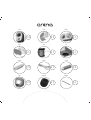
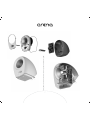
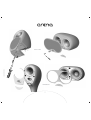
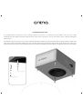
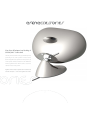
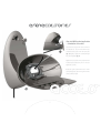
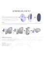
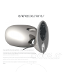
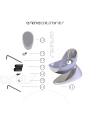
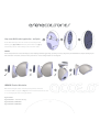
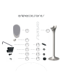
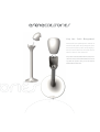
owners manual
Contents
3
3
4-5
6-7
8-9
10 - 11
12 - 13
14 - 15
16 - 17
18 - 19
20 - 21
22 - 23
24 - 26
Contents
Warranty
Unpacking List
Dual ConcentricTM
and WideBandTM Technology
Connections
Positioning
Grille Fixing
Safety Instructions
Positioning and fitting of feet
Setting-up
Technical Specifications
Subwoofer
Satellites
Optional Accessories
WARRANTY
This home theatre system has been produced and
tested with care and precision. It is built to give
first class service and carries a 1-year warranty.
If the equipment proves to be defective within this
period for any reason other than accident, misuse,
unauthorised modification or fair wear and tear,
Tannoy will repair any such defect or, at our option,
replace it without charge for parts, labour or return
carriage. This warranty is given in addition to the
customer’s statutory rights.
If you suspect a problem with your system, please
contact your local Tannoy dealer who will be able
to advise on appropriate action.
3
UNPACKING
Check the contents of the carton to identify the following items:
one
4 x satellite speakers
two
4 x satellite speaker grilles (with 2 x fixing screws each)
three
1 x centre channel speaker
four
1 x centre channel grille (with Hex fixing screw)
five
20m speaker cable
six
1 x subwoofer
seven
4 x extension legs
eight
1 x mains lead
nine
4 x floor spikes
ten
4 x spike lock nuts
eleven
4 x protection boots (for use on polished wooden floors)
twelve
1 x Hex key
Store complete packaging in case it is needed for re-use.
4
one
two
x4
four
three
x4
five
x1
seven
six
x1
eight
x4
ten
x1
x1
nine
x1
eleven
x4
twelve
x1
5
x4
x1
SATELLITES and CENTRE CHANNEL
DRIVER TECHNOLOGY
Dual Concentric™
Tannoy Dual Concentric™ drivers have been incorporated into the Arena system. Intensive research and development has produced an all-new version of this
proven technology that builds upon the legendary performance of this exclusive Tannoy driver design.
The time coherent, point source and constant directivity nature of the dispersion characteristics inherent in the Dual makes it an accepted industry standard
in studio monitoring. By exceeding the rigorous demands of the recording and mastering environment Tannoy can ensure that playback performance in the home
for multi channel home cinema, is strictly controlled to accurately reflect the sound engineers artistry. In nature all sounds emanate from a single point in space.
The high frequency unit of the Dual, centrally mounted in the throat of the main mid/bass driver, is so positioned as to acoustically replicate this single point source;
delivering an incredibly natural sound with an incredibly wide imaging ‘sweet spot’ that creates an expansive soundstage with remarkably focused placement
of images.
WIDEBAND™ Technology
Tannoy has incorporated its own WideBand™ technology into the design of these drivers. Not only does this exceptional in-house technology resolve fine detail of
high frequency information but it also effectively enhances the listening experience throughout the whole frequency range. The WideBand™ high frequency system
creates an increased immediacy, airiness and impact, making music and movie sound more natural and true to life.
Sounds contain transient information and rich harmonics beyond the range of human hearing for pure tones. Even low frequencies have leading edge transients reaching
30kHz. The Tannoy Arena WideBand™ high frequency unit will accurately reproduce the leading edge of individual sounds allowing the listener to experience the entire
bandwidth, by extending the frequency response to 54kHz.
In addition, the extension of the frequency response, by fully two octaves, corrects time and phase response within the bandwidth of normal human hearing. Taking these
acoustical phase anomalies beyond the audible range adds realism to the soundstage through improvements in imaging and the placement of sounds.
6
7
Tannoy Dual Concentric™ drivers have been incorporated into the Arena system.
CONNECTIONS
Using the supplied twin core cable,
connect each channel to the
appropriate output of your AV receiver,
observing polarity - positive to
positive and negative to negative (or
red to red and black to black).
The supplied cable has the negative
( - ) core marked by a black line.
If additional cable is required, your
dealer will be able to advise on a
suitable type.
Additional satellite and centre
speakers are available, should you
wish to expand your system.
8
CENTRE
CHANNEL (C)
FRONT RIGHT
SATELLITE (F/R)
BLACK TERMINAL
NEGATIVE (-)
FRONT LEFT
SATELLITE (F/L)
RED TERMINAL
POSITIVE (+)
BLACK TERMINAL
NEGATIVE (-)
-
F/R
RED TERMINAL
POSITIVE (+)
C
R/R
F/L
-
+
BLACK TERMINAL
NEGATIVE (-)
+
-
RED TERMINAL
POSITIVE (+)
+
R/L
SUB
SUBWOOFER
(SUB)
REAR RIGHT
SATELLITE (R/R)
BLACK TERMINAL
NEGATIVE (-)
REAR LEFT
SATELLITE (R/L)
BLACK TERMINAL
NEGATIVE (-)
RED TERMINAL
POSITIVE (+)
9
RED TERMINAL
POSITIVE (+)
POSITIONING
The centre channel may be placed
either on top of or below the
television or monitor and the front
and rear speakers positioned as
shown on a suitable table or shelf.
All speakers (with the exception of
the subwoofer) are magnetically
shielded to avoid colour distortion
to the television, but as some sets
are more sensitive to interference
than others, some experimentation
in placement may be required,
or the use of the optional table stand
to space the centre speaker further
from the television.
For the satellites, an optional
combined table stand and wall
bracket is available, along
with a floor stand, while a dedicated
table stand/ wall bracket is
available for the centre channel.
REAR
Please consult your authorised
Tannoy dealer.
1.5 TO 4.5 METRES
1.0 METRE
MINIMUM
SUB
0.5 METRE
MINIMUM
10
11
GRILLE FIXING
Fitting of the grilles is optional, using
the supplied hardware. On the
satellites, fix the grille in place using
the 2 screws provided, see
illustration. On the centre channel,
firstly remove the small trim panel
from the front of the speaker, as
illustrated. A Hex key is provided for
tightening the grille mounting screw,
ensure not to over tighten, see
illustration.
TRIM REMOVAL
The Arena satellite and centre both
have a removable front trim which
gives the option of mixing and
matching the speaker body colour
with any of the optional trim colours.
To remove the trim, first remove the
grille if fitted as described above.
Next, place a finger underneath the
bottom centre of the trim and gently
prize out the rubber trim. Remove
this slowly ensuring that all of the
integral fixing studs around the
outside of the trim are pulled out
gently from the body of the speaker.
Replacement of the trim is the exact
opposite of the removal process.
CLEANING
Dust the loudspeakers with a dry
lint free cloth.
12
screwdriver not included
GRILLE FIXING
TRIM REMOVAL
13
IMPORTANT SAFETY INSTRUCTIONS - SUBWOOFER
1
2
3
4
5
6
7
8
9
10
11
12
13
14
15
16
17
Read these instructions.
Keep these instructions.
Heed all warnings.
Follow all instructions.
Do not use this apparatus near water.
Clean only with dry cloth.
Do not block any ventilation openings. Install in accordance with manaufacturer’s instructions.
Do not install near any heat sources such as radiators, heat registers, stoves, or other apparatus (including amplifiers) that produce heat.
Do not defeat the safety purpose of the polarized or grounding-type plug. A polarized plug has two blades with one wider than the other. A grounding type
plug has two blades and a third grounding prong. The wide blade or the third prong are provided for your safety. If the provided plug does not fit into your
outlet, consult an electrician for replacement of the obsolete outlet.
Protect the power cord from being walked on or pinched particularly at plugs, wall sockets, and the point where they exit from the apparatus.
Only use attachments/accessories specified by the manufacturer.
Unplug this apparatus during lightning storms or when unused for long periods of time.
Refer all servicing to qualified service personnel. Servicing is required when the apparatus has been damaged in any way, such as power-supply cord or plug
is damaged, liquid has been spilled or objects have fallen into the apparatus, the apparatus has been exposed to rain or moisture, does not operate
normally, or has been dropped.
WARNING: To reduce the risk of fire or electrical shock, this apparatus should not be exposed to rain or moisture and objects filled with liquids, such as vases,
should not be placed on this apparatus.
To completely disconnect this equipment from the mains, disconnect the power supply cord plug from the wall socket.
The mains plug on the power supply cord shall remain readily accessible.
Due to the powerful drive unit magnet, do not place within (3 feet) 1 metre of a television or computer monitor.
The lightning flash with an arrowhead symbol within an equilateral triangle,
is intended to alert the user to the presence of uninsulated “dangerous voltage” within the
product’s enclosure that may be of sufficient magnitude to constitute a risk of electric
shock to persons.
!
The exclamation point within an equilateral triangle is intended to alert the user to the
presence of important operating and maintenance (servicing) instructions in the
literature accompanying the product.
14
IMPORTANT SAFETY INSTRUCTIONS
Electrical Requirements
Check that the voltage rating displayed on the rear panel is correct for your area before connecting. If it is incorrect, please refer to your
local dealer or authorised service agent, as no user adjustment is provided.
EUROPEAN MODELS
A mains cable is supplied with an IEC moulded socket at one end and a moulded mains plug at the other end. Where the moulded plug is fitted
with a mains fuse, always replace with the same 5A rated fuse.
If the fitted plug is unsuitable for your type of outlet sockets, it should be cut off and disposed of safely, in case it is inserted into a live socket
elsewhere. The wires in the mains cable are coloured in accordance with the following code:
GREEN AND YELLOW
BLUE
BROWN
EARTH
NEUTRAL
LIVE
AS THE COLOURS OF THE WIRES IN THE MAINS CABLE MAY NOT CORRESPOND WITH THE COLOURED MARKINGS IDENTIFYING THE
TERMINALS IN YOUR PLUG, PROCEED AS FOLLOWS:
}
The wire which is coloured GREEN AND YELLOW must be connected to the terminal in
the plug which is marked either by the letter E, the earth safety symbol, or coloured GREEN
or GREEN and YELLOW.
}
The wire which is coloured BLUE must be connected to the terminal in the plug which is marked by the letter N or coloured BLACK.
}
The wire which is coloured BROWN must be connected to the terminal in the plug which
is marked by the letter L or coloured RED.
}
Ensure that the terminals are tightened securely, and no loose strands of wire are present. Ensure cord grip is clamped over outer sheath
of cable, rather than over the wires.
FUSE PROTECTION
An additional mains fuse is provided in the IEC power inlet on the back of the loudspeaker, which can only be removed with the power cord
unplugged. This must be replaced by a fuse of the same type and rating (see Specifications or refer to rear panel).
15
POSITIONING AND FITTING OF FEET
As a subwoofer produces low frequencies only, it is difficult to detect its location by ear. It can therefore be placed anywhere in the room, but it is worth
experimenting to find the optimum position. Bass output will increase next to a wall or especially in a corner; so use the volume control to compensate if moving your
subwoofer around.
This subwoofer is unique in that it can be used in various orientations, depending on available space and desired visual effect. For portrait positioning, screw the metal
spikes into the cabinet, first removing the blanking plugs. Secure using the lock nuts supplied. For driver facing down operation, use the extension legs as shown. For use
on polished wooden floors, reverse the spikes and fit the protective boots provided, to avoid damage. Ensure the subwoofer is sitting firmly on the floor, to avoid vibration.
for use on carpeted floors
for use on polished floors
16
for use on carpeted floors
for use on polished floors
17
SETTING UP
Ensure the main POWER switch is in the OFF position. Connect the subwoofer input socket to the sub out on your AV processor or amplifier, using a screened
phono cable. You can operate the subwoofers in two modes, AUTO and ON continuously, using the switch provided. In AUTO, the unit remains OFF until
an input signal is detected. Status is confirmed by the power light, which glows red in AUTO standby, but is otherwise green.
Firstly set GAIN volume to MIN, and LFE MODE switch to ON. This will bypass the unit’s internal crossover, with this function now provided for within the
AV processor. The XOVER FREQ. Control will no longer be functional. Set the PHASE control to 0 0. The LED will turn green when switched ON, or when a signal is
detected in AUTO mode.
Set the LF EXTENSION control to mid position and play some music or other material through the system and slowly increase the input level control until roughly
the correct amount of bass is present. If this does not prove possible, rotate the PHASE control clockwise, which with some speakers and rooms will give increased
bass output. Moving the LF EXTENSION control anticlockwise towards the MUSIC position will give a deeper more extended bass, while moving it clockwise towards
the THEATRE position will increase the impact of movie sound effects. Fine adjustment of the controls will take a little time using a range of different programme material.
If an even bass performance and seamless transition to the satellites does not prove possible in your room, switch the LFE MODE switch to
OFF and experiment with the crossover frequency. It is often possible to reduce the influences of harmful room resonances in this manner.
AUTO POWER/ SLEEP FUNCTION
This subwoofer can be left permanently on in AUTO mode, under which conditions it will revert to ‘sleep’ mode after approximately
12 minutes. If not using your subwoofer for some time, switch OFF and remove the power cable from the mains outlet.
OVERLOAD PROTECTION
The Arena subwoofer is provided with circuitry to limit the maximum sound output, in order to eliminate audible distortion. This circuitry will normally operate
unnoticed. If however distortion is heard, this indicates the unit is being severely overloaded, and to avoid damage, the input level should be reduced immediately.
CLEANING
Dust the enclosure with a dry lint free cloth. Do not use any solvent-based chemicals.
18
1 ON / AUTO | 2 Phase (Degrees) | 3 LF Extension | 4 Volume | 5 LFE MODE
19
| 6 Crossover (Hz)
TECHNICAL SPECIFICATION Subwoofer
Output Power
Low Frequency Response (-6dB)
Limit for usable output
Input
Input Filter
Auto Mute
Driver Type
Enclosure Type
Enclosure Volume
Additional Features
Enclosure Dimensions
(Excluding feet)
Enclosure Weight
Mains Voltage
Mains Fuse
Maximum Power Consumption
Weight
20
300W RMS
29Hz
16Hz
1 x line level phono
2nd order low pass, 50Hz – 150Hz, -6dB.
After approximately 12 mins, in absence of input signal
250mm (10”)
Closed box
20.0L litre/ 0.7 cu.ft
Phase control
Crossover defeat switch for LFE operation
Soft limiting to avoid overload
LF extension control
445 x 350 x 210mm
171/2 x 133/4 x 81/4”
14kg / 30.8 lbs
120V nominal AC ~, 60Hz
230V nominal AC ~, 50Hz
120V - T3.15AL/250V
230V - T1.6AL/250V
416VA
14.5kg (32lbs)
TECHNICAL SPECIFICATION
350.0mm
133/4”
445.0mm
171/2”
210.0mm
81/4”
INC. GRILLE
190.0mm
71/2”
EXC. GRILLE
270.5mm
105/8”
21
Crossover type
Dual Concentric Driver
Bass Driver (Centre only)
Enclosure Type
Internal volume (Satellite)
Internal volume (Centre)
TECHNICAL SPECIFICATION Satellites & Centre
Recommended amplifier power
Sensitivity (2.83V @ 1m)
Nominal impedance
Frequency response (-6dB)
Crossover frequency
Dimensions (Satellite)
Including Grille
Dimensions (Centre)
Including grille
Weight (Satellite)
Weight (Centre)
15- 100W
88dB
8 ohm
80Hz- 54kHz
1.75kHz mid to high
80Hz to subwoofer
2nd order low pass
1st order high pass
LF 100mm mixed fibre pulp cone
Dynamic overload protection
HF 19mm titanium dome with
neodymium magnet system
100mm mixed fibre pulp cone
Ported
2.0L, 0.07cu.ft
2.6L, 0.09cu.ft
187.0mm x 133.5mm x 175.5mm
73/8” x 51/4” x 67/8”
133mm x 245mm x 149mm
51/4” x 95/8” x 57/8”
2.5kg (5.5lbs)
4.0kg (8.8lbs)
22
175.5mm INC. GRILLE
67/8”
133.5mm
51/4”
180.0mm
71/16”
EXC. GRILLE
164.5mm EXC. GRILLE
61/2”
187.0mm
73/8”
INC. GRILLE
149.0mm INC. GRILLE
57/8”
245mm
95/8”
138.0mm EXC. GRILLE
57/16”
133mm
51/4”
23
optional accessories
1018.0mm
401/16”
280.0mm
11”
260.0mm
101/4”
24
133.5mm
51/4”
245.0mm
95/8”
276.5mm
107/8”
237.5mm INC. GRILLE
93/8”
226.5mm EXC. GRILLE
815/16”
226.5mm INC. GRILLE
815/16”
215.5mm EXC. GRILLE
81/2”
210.0mm
81/4”
268.0mm
109/16”
218mm INC. GRILLE
89/16”
207.0mm EXC. GRILLE
81/8”
229mm INC. GRILLE
9”
218.0mm EXC. GRILLE
89/16”
25
optional accessories
191.0mm
71/2”
optional accessories
Centre Channel shown with optional stand mount
Satellite shown with optional wall bracket
26
Tannoy adopts a policy of continuous improvement and product specification is subject to change. E. & O.E.
This equipment has undergone safety and EMC testing, and complies with the European Low Voltage Directive and Electromagnetic Compatibility Directive,
together with the requirements of the Canadian Standards Association (CSA).
Centre Channel Stand / Wall Bracket Accessory Manual
4mm Allen key for stand to centre fixing screws
x1
stand to centre fixing screws
x2
shake proof washer for stand fixing screws
x2
3mm Allen key for ball joint screws
x1
Table stand
3
x1
Cable management routing through ball joint
Step one: Satellite fixing bracket
Step two: Cable management – table
stand application
Ensure that the audio system amplifier is switched
off and then feed the speaker cable up through the
base and ball joint of the stand. Prepare the speaker
cable by stripping 6mm (1/4 inch) of insulation and
connect to the relevant terminal on the base of the
centre speaker unit.
The positive conductor (marked with line, text print
or raised rib) connects to the terminal with the red
insert ring while the negative cable goes to the
terminal marked with the black insert.
4
Step three: Centre channel fitting to stand
Locate the unit into the cradle of the table / wall stand, ensuring
that the speaker cable is carefully routed to avoid damage.
Using the 4mm Allen key, insert the two chrome screws and
lock washers into the underside of the unit and tighten to fully
secure the unit.
5
Step four: Grille fitting
If intending to use the grille you must remove the
coloured trim piece using the finger recess behind the
trim and locate the bottom section of the grille into
the recess on the stand. Use the 4mm Allen driver to
insert chrome screw to secure the grille in place.
The grille is designed to stand off from the front baffle
of the satellite so do not over tighten the screw.
6
Step five: Adjustment and locking of
the ball joint – table stand
The ball joint mechanism allows great flexibility in the
positioning of the centre speaker in relation to the
stand. Simply move the speaker to desired position, set
in the required orientation and then use the 3mm Allen
driver to tighten the four chrome screws to secure the
satellite in the desired position.
Tighten all four evenly at quarter turn increments to
lock the ball joint - do not over tighten the screws.
7
Step six: Wall bracket application
– orientation of bracket
The universal design of the stand allows for
wall mount use. Use the 3mm Allen key to
1
slacken the four screws on the ball joint plate
(fig. 1) slightly – rotate the assembly through
1800 and retighten (fig. 2).
Tighten all four screws evenly at quarter turn
increments to lock the ball joint - do not over
tighten the screws.
Route the signal cable from the base of the
stand through the cable management in the
centre of the ball joint
2
8
Step seven: Wall bracket application – wall plate
1
2
3
Use the 4mm Allen key to remove the chrome screw retaining the wall
mounting plate (figs.1 and 2). Remove the plate from the base (fig. 3)
and mark the positions of the mounting screws on the wall surface.
WARNING:
Ensure that you utilise the correct wall fixings (screws, Rawlplug, Rawlbolt, toggle fixing, expanding insert etc) designed to provide maximum security of fastening to your
wall construction. If in doubt you must consult a professional – incorrect fixing methods can be dangerous.
4
5
6
7
3
7
7
7
WARNING: Product Orientation
When wall mounting the Centre or Satellite product you must ensure that
it is installed ONLY as it appears in Fig 1 above. The lock washer must also be used,
as it is an integral part of the securing mechanism.
Fig 4: CORRECT
Fig 5: INCORRECT – lock washer missing
Fig 6: INCORRECT ORIENTATION
Fig 7: INCORRECT ORIENTATION
9
Step eight: Wall bracket application – fixing to wall and adjustment
Carefully dress the signal cable through the cable management and offer the bracket base to the
secured wall mount plate. Using the 4mm Allen key, insert the chrome screw through the bracket and
tighten to secure the assembly to the wall plate.
Simply move the speaker to set the set the required orientation and then use the 3mm Allen driver to
tighten the four chrome screws to secure the satellite in the desired position.
Tighten all four screws evenly at quarter turn increments to lock the ball joint - do not over tighten the
screws.
10
Satellite Table Stand / Wall Bracket Accessory Manual
Grille
x1
Grille fixing screw
x1
4mm Allen key for grille screw
x1
Unit bracket assembly
x1
Unit fixing screw
x4
Unit fixing washer
x4
3mm Allen key for ball joint screws
x1
Table stand
3
x1
Step one: Satellite fixing bracket
Using the bracket, screws and lock washers fix the
unit bracket assembly to the base of the satellite;
taking care to locate the two locating pins at the
front of the bracket into the holes in the base of
the casting.
4
Step two: Cable management – table
stand application
Ensure that the audio system amplifier is switched off
and then feed the speaker cable up through the base
and ball joint of the stand. Prepare the speaker cable
by stripping 6mm (1/4 inch) of insulation and connect
to the relevant terminal on the base of the
satellite unit.
The positive conductor (marked with line, text print or
raised rib) connects to the terminal with the red insert
ring while the negative cable goes to the terminal
marked with the black insert.
5
Step three: Satellite fitting to stand
Locate the satellite into the cradle of the table / wall
stand, ensuring that the speaker cable is carefully
routed to avoid damage, before using the remaining
screws and lock washers to fully secure the unit.
If no grille is to be used, cover the fixing screws with
the coloured trim piece by locating the pins
on the trim into the holes on the stand and pressing
into the recess.
6
Step four: Grille fitting
If intending to use the grille you must remove the
coloured trim piece using the finger recess behind the
trim and locate the bottom section of the grille into the
recess on the stand. Use the 4mm Allen driver to insert
chrome screw to secure the grille in place.
The grille is designed to stand off from the front baffle
of the satellite so do not over tighten the screw.
7
Step five: Adjustment and locking
of the ball joint – table stand
The ball joint mechanism allows great flexibility
in the positioning of the satellite in relation
the stand.
Simply move the speaker to desired position,
set in the required orientation and then use
the 3mm Allen driver to tighten the four chrome
screws to secure the satellite in the desired
position.
Tighten all four evenly at quarter turn
increments to lock the ball joint - do not
over tighten the screws.
8
1
2
Step six: Wall bracket application – orientation of bracket
The universal design of the stand allows for wall mount use. Use the 3mm
Allen key to slacken the four screws on the ball joint plate (fig. 1) slightly –
rotate the assembly through 1800 and retighten (fig. 2).
Tighten all four screws evenly at a quarter turn increments to lock the ball
joint - do not over tighten the screws.
Route the signal cable from the base of the stand through the cable management
in the centre of the ball joint
9
Step seven: Wall bracket application – wall plate
1
2
3
Use the 4mm Allen key to remove the chrome screw retaining the wall
mounting plate (figs.1 and 2). Remove the plate from the base (fig. 3)
and mark the positions of the mounting screws on the wall surface.
WARNING:
Ensure that you utilise the correct wall fixings (screws, Rawlplug, Rawlbolt, toggle fixing, expanding insert etc) designed to provide maximum security of fastening to your
wall construction. If in doubt you must consult a professional – incorrect fixing methods can be dangerous.
4
5
6
7
3
7
7
7
WARNING: Product Orientation
When wall mounting the Centre or Satellite product you must ensure that
it is installed ONLY as it appears in Fig 1 above. The lock washer must also be used,
as it is an integral part of the securing mechanism.
Fig 4: CORRECT
Fig 5: INCORRECT – lock washer missing
Fig 6: INCORRECT ORIENTATION
Fig 7: INCORRECT ORIENTATION
10
Step eight: Wall bracket application –
fixing to wall and adjustment
Carefully dress the signal cable through the cable management and
offer the satellite bracket base to the secured wall mount plate.
Using the 4mm Allen key, insert the chrome screw through the
bracket and tighten to secure the assembly to the wall plate.
Simply move the speaker to set the required orientation and then
use the 3mm Allen driver to tighten the four chrome screws to secure
the satellite in the desired position.
Tighten all four screws evenly at quarter turn increments to lock
the ball joint - do not over tighten the screws.
11
Floor Stand Accessory Manual
Grille
x1
Grille fixing screw
x1
4mm Allen key for grille screw
x1
Spike
x8
Unit bracket assembly
x1
Spike washer
x8
Unit fixing screw
x4
Spike nut
x8
Unit fixing washer
x4
Rubber foot
x8
Floor stand
2
x1
Step one: Satellite fixing bracket
Using the bracket, screws and lock washers fix the
unit bracket assembly to the base of the satellite;
taking care to locate the two locating pins at the
front of the bracket into the holes in the base of
the casting.
3
Step two: Cable Management
Ensure that the audio system amplifier is switched off
and then feed the speaker cable up through the column
of the stand. Prepare the speaker cable by stripping a
6mm (3/4 inch) of insulation and connect to the relevant
terminal on the base of the satellite unit.
The positive conductor (marked with line, text print or
raised rib) connects to the terminal with the red insert
ring while the negative cable goes to the terminal
marked with the black insert.
4
Step three: Satellite fitting to stand
Locate the satellite into the cradle of the floor stand,
ensuring that the speaker cable is carefully routed to
avoid damage, before using the remaining screws and
lock washers to fully secure the unit.
If no grille is to be used, cover the fixing screws with
the coloured trim piece by locating the pins on the
trim into the holes on the stand and pressing into
the recess.
5
Step four: Grille fitting
If intending to use the grille you
must remove the coloured trim
piece using the finger recess
behind the trim and locate the
bottom section of the grille into
the recess on the stand. Use the
4mm Allen driver to insert
chrome screw to secure the grille
in place.
The grille is designed to stand
off from the front baffle of the
satellite so do not over tighten
the screw.
6
Step five: spike fitting – carpeted floors
Thread the nuts and washers onto the spikes and screw into
each of the four threaded inserts on the base. Adjust the spikes
to level the stand and then tighten the lock nuts.
Return the stand to the upright position in the desired location.
To achieve optimum performance press firmly down to ensure
the spikes penetrate the carpet and contact the floor.
Step five: rubber feet –
wooden or tiled floors
To avoid damage to sensitive floor
surfaces the spikes should not be used.
Instead, the supplied rubber feet should
be placed over the threaded inserts.
7
Tannoy United Kingdom
T: +44 (0) 1236 420199
F: +44 (0) 1236 428230
E: [email protected]
Tannoy North America
T: (519) 745 1158
F: (519) 745 2364
E: [email protected]
6481 0426
Check periodically for the latest manual revision that will always available for download from
www.tannoy.com The revision number of this manual is located below