1
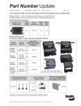
H0420
Programmable MP3 Audio Controller for Exhibitions and Kiosk Applications
User Guide
ITB CompuPhase
Tel.: +31 (0)35 6939261
Eerste Industriestraat 19-21
Fax.: +31 (0)35 6939293
1401 VL Bussum, The Netherlands
[email protected]
www.compuphase.com
2009-05-05
1
Table of Contents
Preliminary..............................................................................................................................................2
Anti-static handling precautions...............................................................................................................2
Power supply voltage range......................................................................................................................2
Legal disclaimer.......................................................................................................................................2
Overview of the H0420............................................................................................................................3
Connecting the H0420.............................................................................................................................3
CompactFlash card...................................................................................................................................3
Power connector.......................................................................................................................................4
Audio outputs...........................................................................................................................................4
Button inputs............................................................................................................................................4
General purpose input/output pins............................................................................................................5
LCD connection.......................................................................................................................................6
RS232.......................................................................................................................................................7
Mechanical montage................................................................................................................................7
Contents of the CD-ROM........................................................................................................................9
Installing the development tools..............................................................................................................9
Using the ready-made scripts...................................................................................................................9
Writing scripts.........................................................................................................................................9
Further reading.......................................................................................................................................12
Transferring files...................................................................................................................................12
MP3 file requirements............................................................................................................................13
Track duration & seeking to a position...................................................................................................13
ID3 Tags and synchronized events.........................................................................................................13
Adding “synchronized lyrics” to an MP3 file.........................................................................................14
Trouble shooting....................................................................................................................................15
Specifications.........................................................................................................................................16
General...................................................................................................................................................16
Audio......................................................................................................................................................16
Control...................................................................................................................................................16
Mechanical.............................................................................................................................................16
Operating conditions..............................................................................................................................16
Firmware................................................................................................................................................16
Preliminary
Anti-static handling precautions
Please observe anti-static handling precautions when handling the device, as it contains components that are
sensitive to static discharges.
Power supply voltage range
Please verify the power supply voltage to be within the range that the device supports, and that the polarity is
correct. See page 15 for the specifications and page 4 for the power connector. Voltages outside the
appropriate range may cause malfunction. Voltages above the high limit or with inverted polarity may
damage the device.
Legal disclaimer
ITB CompuPhase shall not be liable for the incidental or consequential losses or damage to tangible property,
injury or death of a person in connection with the use of this device. Although the examples in this guide
have been tested with care, they may contain errors and they are not guaranteed for any particular purpose.
2
Overview of the H0420
The H0420 is a compact and solid state general purpose controller with an embedded MP3-audio
decoder that runs under the control of a scripting language. The audio fragments and the script that
controls the operation and behaviour of the MP3 player are stored on a CompactFlash card. Auxiliary
devices, such as an LCD, (electronic) switches or data terminals may be attached through a 16-bit
general purpose I/O bus, a standard header connector supporting 16 switches, and an RS232
connector respectively.
This booklet introduces the scripting capabilities of the H0420 MP3 controller. For technical details
and a programming reference, please see the documentation that is provided in Adobe Acrobat
format on the CD-ROM that comes with the product.
The script controls the operation of the H0420 and the peripherals. The script must be written in the
PAWN language and be stored (in compiled form) on the CompactFlash card under the name of
“AUTORUN.AMX” in the root directory. In absence of a script, the H0420 plays all MP3 files on the
CompactFlash card in a random sequence. To react on switches or I/O pins and to communicate over
RS232 or an optional LCD, a PAWN script is required.
Connecting the H0420
CompactFlash card
Connector K1 accepts CompactFlash cards types 1 and 2. The firmware supports cards formatted
with FAT16 and FAT32, and it uses the first suitable partition. The firmware supports subdirectories,
encrypted volumes (partitions) and encrypted MP3 tracks, using strong encryption with a 128-bit key.
The CompactFlash card must contain all MP3 audio tracks. Typically, it will also contain a
programmed “script” that determines how the device responds to various inputs —for example, by
playing different audio tracks for each switch that is pressed.
3
Power connector
The power connector is a standard low
voltage power connector with a pin size of
2.1 mm. The pin is the plus pole.
Inverting the polarity
damages the device.
Audio outputs
Two RCA connectors provide analogue
stereo output. The red connector is for the
right channel. RCA connectors are also
called “phono” connectors, or “CINCH”
connectors.
For good sound quality, the input impedance
of the equipment (e.g. an amplifier) that is
attached to the audio outputs should be at
least 2.7 kΩ. When connecting the audio
outputs to equipment with low impedance,
low frequencies are cut off.
Button inputs
Connector block J5 allows up to 16 switches to be
attached to the controller.
A switch is “down” when the “sense” pin is
shorted to the respective “ground” pin (see the
table below). Each sense pin has a weak pull-up, a
bounce filter and a Schmitt trigger (hysteresis
circuit).
The maximum switch frequency that can be
detected is 50 Hz.
The switch inputs may also be used to detect logic levels from other digital equipment (such as TTL
levels). Because of the internal pull-up resistors, open-drain outputs can be connected to the “sense”
pins as well.
J5 is a 2.54 mm pitch IDC header. The triangle on the connector indicates pin 1.
4
J5
1
3
5
7
9
11
13
15
17
19
21
23
25
27
29
31
33
2
4
6
8
10
12
14
16
18
20
22
24
26
28
30
32
34
Switch 0 sense pin
Switch 1 sense pin
Switch 2 sense pin
Switch 3 sense pin
Switch 4 sense pin
Switch 5 sense pin
Switch 6 sense pin
Switch 7 sense pin
Switch 8 sense pin
Switch 9 sense pin
Switch 10 sense pin
Switch 11 sense pin
Switch 12 sense pin
Switch 13 sense pin
Switch 14 sense pin
Switch 15 sense pin
Not connected
Ground
Ground
Ground
Ground
Ground
Ground
Ground
Ground
Ground
Ground
Ground
Ground
Ground
Ground
Ground
Ground
Ground
General purpose input/output pins
J6 and J7 are 2.54 mm pitch IDC headers that
provide, in total, 16 digital pins. Each digital
pin can be configured as input or output. The I/
O pins are filtered to a maximum switching
frequency of approximately 50 kHz; however
the maximum I/O switching rate is
approximately 4 kHz.
In addition to the digital pins, J6 provides one
analogue output pin. In addition to a fixed
voltage between 0 and 5 V, this pin can produce
a wave signal at a frequency between 0.001 Hz
and 10 kHz (sine, square, triangle and sawtooth).
When configured as inputs, the pins are TTL-compatible, with high impedance and weak pull-up
resistors.
When configured as outputs, each pin either provides a TTL-level signal, or it can drive a LED (or
similar load, like an opto-coupler); usually no external current limiting resistor is needed for driving
a LED because each output pin is equipped with an internal current limiting resistor (220 Ω). The
current limit depends on the LED's forward voltage; it is ~14mA at 2V. The current for all the pins
(16 digital) combined may not exceed 160mA. Because of the current limiting resistors, outputs are
TTL compatible only under the following conditions:
High level................................>2 V at < 10 mA source
Low..........................................<0.8 V at < 0.9 mA sink
The triangle on the connectors indicate pin 1 (see the pictures above and below).
5
1
3
5
7
9
11
13
15
2
4
6
8
10
12
14
16
Ground
Analogue out (0 to 5V)
IO9
IO0 (Digital I/O pin 0)
IO2
IO4
IO6
Power supply, 5V
Logic power supply, 5V
IO8 (Digital I/O pin 8)
IO10
IO1
IO3
IO5
IO7
Ground
J6
The combination of all I/O pins and the filtered power supply at pin 2 may draw 160 mA maximum.
Pin 15 of connector JP6 is connected directly to the power connector; you can use this pin to draw
higher currents.
1
3
5
7
9
2
4
6
8
10
Ground
Ground
Ground
Ground
Ground
IO11
IO12
IO13
IO14
IO15
J7
LCD connection
Connector block J6 can serve as an LCD
connector. The pin lay-out conforms to the
standard LCD-interface with HD44780 controller
(see the table below). J6 is a 16-pin IDC header
with a pitch of 2.54 mm.
Connector J6 provides either LCD driving
function, or eleven digital I/O pins and one
analogue output pin. The choice between these
two functionalities is software-controlled.
The LC-driving voltage on pin 3 is a softwarecontrolled voltage between 0 and 5 V. LCDs that use a positive LC-driving voltage (Vo) are directly
supported; LCDs that needs a negative LC-driving voltage should use a voltage inverter on pin 3.
When attaching a backlight unit to the connector on pins 15 and 16, you may need to put a resistor in
the power line (pin 15). In the H0420, pin 15 is connected directly to the power connector.
The triangle on the connector indicates pin 1 (see the picture).
6
1
3
5
7
9
11
13
15
2
4
6
8
10
12
14
16
Ground (Vss)
LC-driving supply (Vo)
Read/write (R/W)
Data bit (DB0)
Data bit (DB2)
Data bit (DB4)
Data bit (DB6)
Backlight power, 5V (A)
Logic power supply, 5V (Vdd)
Register Select (RS)
Enable (E)
Data bit (DB1)
Data bit (DB3)
Data bit (DB5)
Data bit (DB7)
Backlight ground (K)
J6
RS232
The device provides a standard 9-pin RS232
connector, and it is configured as a DCE
device (Data Communications Equipment).
Internally, the DTR and DSR lines are
connected, and the RTS and CTS lines are
connected too. A standard “straight
connection” cable should therefore be
suitable (do not use a null-modem cable).
The RS232 interface optionally supports the
XON/XOFF protocol (software
handshaking). Hardware handshaking protocols are not supported.
The settings of the RS232 interface (baud rate, number of stop and data bits) is controlled by the
script on the CompactFlash card.
RS232
1
2
3
4
5
N.C.
TxD
RxD
Internally connected to pin 6
Ground
6
7
8
9
Internally connected to pin 4
Internally connected to pin 8
Internally connected to pin 7
N.C.
Optionally, you can also use the RS232 to upload or download files to/from the CompactFlash card,
using the “FileLink” utility, see page 11.
Mechanical montage
Four mounting holes with a diameter of 3.1 mm (suitable for M3 screws or 1/8” screws) are spaced at
90 mm horizontally and 60 mm vertically. Ensure at least 3 mm of clearance below the PCB. See the
datasheet for details and drawings.
The mounting holes are (electrically) connected to the digital and analogue ground of the device.
When the H0420 ground must be isolated from a (grounded) metal enclosure, use nylon washers and
nylon machine screws for fastening.
7
Contents of the CD-ROM
The product comes with a CD-ROM containing:
• Several ready-to-run and fully documented scripts that can be configured through an “INI” file and
a “playlist” file. No programming is required to run these scripts.
• The PAWN development tools: the compiler, the debugger and configuration files.
• Auxiliary utilities, such as a file transfer utility and a serial monitor program.
• An assortment of example scripts in source code form, to get you starting with programming the
H0420 MP3 controller.
• Extensive documentation in Adobe Acrobat format: the PAWN language manual, the H0420
programming reference, and the H0420 datasheet with detailed electrical and mechanical
information.
• Example MP3 tracks, for testing purposes.
Installing the development tools
On Microsoft Windows, run the application called “Setup” on the CD-ROM. Then follow the
directions of the installation utility. The installer allows you to choose various optional components
for installation.
The CD-ROM also contains all files and tools in uncompressed form. This may be convenient if you
do not wish to install the entire package. Many of the tools also run directly from the CD-ROM.
Using the ready-made scripts
You may first want to try whether one of the standard, ready-made scripts fits your requirements. The
ready-made scripts are documented in HTML pages, an links to these pages appear in the “Program
Files” menu (after installing the CD-ROM).
The ready-made scripts ready the audio tracks to play from a playlist that conforms to the WinAmp
M3U specification. The scripts may optionally be configured through a standard text file in “INI” file
format. All configuration options are described in the aforementioned HTML pages.
The ready-made scripts may also serve as more advanced examples for coding your own scripts.
Each of the ready-made scripts comes with the full and commented source code. To use the scripts,
no programming or build step is required, because the scripts come in a form that is directly usable
by the MP3 controller (“pre-compiled”).
Writing scripts
Scripts for the H0420 are in the PAWN language. To type in and build the scripts, you use the
“Quincy IDE” that is part of the PAWN development tools, or any standard text editor. When saving
the script's source code, we suggest the extension “.p” or “.pawn”.
8
The Quincy IDE
A minimal script, that plays one file on power-on and then stops, is:
@reset()
play "track1.mp3"
The H0420 controller does not interpret the source code of the script directly, but it executes a
compiled form of the script. You can compile directly from the Quincy IDE, or use the separate
PAWN compiler in a console window or “DOS box”.
The PAWN compiler generates the file “AUTORUN.AMX” from the input file —which is the name that
the H0420 requires. The next steps are to copy the “AUTORUN.AMX” file to the CompactFlash card (in
the root directory), insert that card in the H0420 controller and restart the controller. In the Quincy
IDE you can also adjust the output path so that the source file gets compiled directly onto the
CompactFlash card.
Typically, a script must do a lot more than play just a single file. At the very least, it should allow to
re-start playing one or more audio files without needing to power-cycle the device. More commonly,
the script must react on (user) input in the form of switches or digital levels from sensors.
Below is an example script that reacts on eight switches and plays a “track” in response to each
switch. In addition, it configures I/O pin 15 as output and toggles it on when playing a track (and
back off when playback stops).
const BusyPin = 15
new
current = -1
@reset()
{
configiopin BusyPin, Output
}
@button(pin, status)
{
/* if already playing the selected track, ignore this button press */
if (current != pin && status)
{
current = pin
9
}
switch (pin)
{
case 0: play
case 1: play
case 2: play
case 3: play
case 4: play
case 5: play
case 6: play
case 7: play
}
}
"Track1.mp3"
"Track2.mp3"
"Track3.mp3"
"Track4.mp3"
"Track5.mp3"
"Track6.mp3"
"Track7.mp3"
"Track8.mp3"
@audiostatus(AudioStat: status)
{
if (status == Stopped)
{
setiopin BusyPin, 0
current = -1
}
else
setiopin BusyPin, 1
}
The script starts by defining a constant, “BusyPin”, to indicate pin 15. Although not required, it is
good practice to give symbolic names to constants such as pin numbers. Next is the definition of a
global variable that holds the track currently begin played (or -1 if none). On power-up, the device
will first execute the function “@reset()”; this function is therefore the place to do any initializations.
In the above script, it configures I/O pin 15 as output and sets it to zero.
Function @reset() only runs on power-up or reset of the device. When and event occurs, or the status
of the device changes, it invokes an appropriate “public function”. In the case of the H0420, all
public functions start with an “@” symbol, please see below for a list of available public functions.
This example script uses two public functions: “@button()” is invoked on a switch press or switch
release (whether it concerns a press or a release is in the parameter “status”), and “@audiostatus()”
executes when the device starts or stops playing.
If you attach a LED between pins 14 and 15, this will light up when audio output is active (in other
words, the LED is a “busy” indicator). No resistor is required in from of the LED, as the H0420 has
internal current-limiting resistors on all digital I/O pins.
If a switch is pressed while the controller plays audio, the controller switches to the new track —
aborting the current track. There is an exception when the chosen track already plays: the track will
not restart from the beginning in this case.
As is apparent from the example script, the PAWN language contains all common control constructs:
loops, conditional execution, compound blocks, etc. It also provides an assortment of “native
functions”, such as “setiopin()” or “play()”. These are built-in routines that the H0420 MP3 controller
provides. All native and public functions for the H0420 are documented in the “H0420 programming
reference”.
Further reading
For starting to script your H0420, the first book to reach for is the H0420 “Programming Guide &
Reference”. Next to the documentation for all public and native functions, this book also contains an
assortment of programming examples, ranging from simple to extensive.
10
If you are new to the PAWN language, the introductory chapter of the book “The PAWN booklet —
The Language” will give you a tutorial with example programs and a gentle introduction to
programming. This book also describes the error messages of the PAWN compiler, with hints for how
to fix the syntax or pointers to more information. The “Language Guide” also contains the official
specification of the PAWN language.
To connect the H0420 to other devices (computers, amplifiers, sensors, switches, etc.), refer to the
product's datasheet for hardware specifications and mechanical drawings.
The CompuPhase web site features an assortment of Application Notes describing special use (and
special extensions) of the H0420. Examples of such notes are:
• Introduction to programming the H0420: responding to switches
• Using a remote control (for television and VCR) to control the H0420
• Synchronizing events with music, using the ID3 tag
• Synchronizing the internal clock of the H0420 on the DCF77 or MSF time code
• Connecting the H0420 to a MIDI chain (create or react on MIDI events)
• Connecting an LCD that needs a negative LC-driving voltage
See http://www.compuphase.com/mp3/ for details.
Transferring files
The FileLink utility on the CD-ROM allows you to transfer files between the H0420 and a PC
(running Microsoft Windows) over an RS232 connection. After starting the FileLink utility, the
H0420 must be reset (via the reset button, a power cycle, or a programmatic reset).
The FileLink utility
11
MP3 file requirements
Originally, the abbreviation “MP3” stood for MPEG version 1, Layer 3 audio. For MPEG
compressed audio, there now exist various versions and the name “MP3” denotes the class of MPEG
layer 3 formats regardless of the version. The H0420 is compatible with versions 1, 2 and 2.5 in
Layer 3 format. Versions 2 and 2.5 of the MP3 format extend it to lower sampling frequencies and
lower bit rates, so that voice audio or low/medium quality music could be compressed more
compactly than with version 1. The H0420 does not support layers 1 or 2 of the MPEG audio format.
These formats have become obsolete.
Track duration & seeking to a position
Within the format for MPEG Layer 3 audio, there are the encoding varieties “constant bit rate”
(CBR), “variable bit rate” (VBR) and “average bit rate” (ABR). The H0420 supports all three types.
For VBR and ABR files must have a “Xing” header to support “direct jumps” to a specific position
in the MP3 track. Without this header, jumps to a position may be inaccurate for VBR and ABR files
and the reported track duration is inaccurate as well. Reported durations and direct jumps are always
accurate for CBR files.
ID3 Tags and synchronized events
The scripting language gives the programmer access to the information in an ID3 tag (version 2),
with information on the artist, album & track, full title, copyright, duration. Details and “informal
standards” of the ID3 tags are available on the web site http://www.id3.org/.
The supported frames in the ID3 tag are:
Tag
Description
TIT2
Song title
TPE1
Performing artist
TALB
Album title
COMM
Comment
TCOP
Copyright
TYER
Year
TRCK
Track (on the album)
TLEN
Duration of the audio track in milliseconds
SYLT
Synchronized lyrics
In addition to the standard “authoring” information, the H0420 supports the optional “synchronized
lyrics” frame in the ID3 tag. The contents in this frame will cause scriptable events to be “fired” on
the time stamps that are attached to each line of lyrics. Although the synchronized lyrics frame was
originally designed for purposes of karaoke and sub-titling songs, another use would be to tag timestamped cues or commands at specific positions in a song or audio fragment.
Adding “synchronized lyrics” to an MP3 file
The first step in making a script react on synchronized events in an MP3 file is to attach an ID3 tag
with the “SYLT” frame to that file. Many ID3 tag editors are available, both freeware and
12
commercial, but only few support the SYLT frame that is needed for synchronized lyrics. When
choosing an ID3 tag editor, verify that it has the required capabilities.
Synchronized lyrics is a set of plain text strings where each string has a time-stamp, in milliseconds
from the start of the audio track. After having added the public function “@synch()” to your script,
this function will be invoked (or called) at the precise time-stamps of each string and with the text of
the string as a parameter.
For purposes of Karaoke, the text strings will indeed be the lyrics of the piece. For other applications,
the time-stamped text may consist of strings like “Close-valve #1”, or “Next_slide”. It is up to your
script to interpret the text strings that it receives and to act upon them.
Encrypted MP3 tracks
The H0420 supports MP3 tracks that are encrypted with 128-bit device key, plus an optional 32-bit
user key. The device key is hard-coded in the device; only H0420 units with the correct key can play
back the encrypted tracks. When ordering a series of MP3 players, a customer may request a unique
device key for that series. In addition to the key, the customer also receives a programs for encrypting
MP3 tracks.
ID3 tag information (version 2) is preserved and non-encrypted. However, the ID3 tag should not be
modified after encrypting the file.
13
Troubleshooting
If you have a multimeter, verify the voltage and the polarity of the power supply. Refer to page 15 for
the power requirements and to page 4 for the polarity. A tension that is too high or an inverted
polarity may damage the device.
To verify the basic operation of the device, reformat the CompactFlash card with FAT or FAT32 and
put a single MP3 file on the CompactFlash card. The card should not contain any script
(“AUTORUN.AMX”). The name of the MP3 track is not important, but the file extension must be
".mp3". Connect power to the H0420 and then insert the CompactFlash card. After a short delay (1 or
2 seconds) the LED behind the RS232 connector should light up and stay on for the duration of the
MP3 track. If you connect the audio outputs of the MP3 controller to an amplifier (or to amplified
speakers), you will be able to hear the track playing. For MP3 tracks that contain large ID3 tags (see
page 12), it may take several seconds before audio output starts.
If the above test fails, remove power and the CompactFlash card. Then, connect a serial cable
between the H0420 MP3 controller and a PC; this must be a straight cable —do not use a nullmodem cable. If your PC lacks a serial (RS232) port, you can alternatively use a converter from USB
to RS232. On the PC, launch The "Termite" utility that comes with the H0420 (other serial terminal
programs work too). Please verify that the COM port is correct and that the serial settings are:
Baud rate
57600
Data bits
8
Parity
none
Stop bits
1
Hardware handshake
none
With the serial cable connected, but without CompactFlash card inserted, plug the power cable into
the H0420 MP3 controller. If the device was already powered, disconnect the power plug and
reconnect it after a two-second delay —this is called a “power cycle”. After connecting the power,
the terminal program should display a message similar to:
H0420-C 1.7 (4036)
The letter "C" may also be a "CE" (depending on the options); "1.7" is the version number of the
firmware and "(4036)" is an internal revision number.
If the above line of text does not appear, check the serial cable, and the settings of the terminal
program. Make sure that you use the correct COM port. If the H0420 persists in remaining silent,
please verify the power supply.
After passing the above test, insert the CompactFlash card in the H0420 MP3 controller (without
removing the power connector). The terminal window should display "Start-up" and start playing the
MP3 track on the card after a short delay. If the terminal window shows anything else than the line
"Start-up", the H0420 failed to read the CompactFlash card. The text of the message tells you why
the H0420 failed to read the card (e.g. wrong file system).
14
Specifications
General
Power input requirements.....................4.1 V to 5.5 V DC.
Current consumption.............................140 mA with audio output; 50 mA in stand-by mode.
Storage medium....................................CompactFlash cards, types 1 and 2.
EMC / ESD...........................................I/O lines and pins are EMC-filtered and ESD-protected.
Conformity............................................EN 55022, EN 55024 (European Community); RoHS.
Audio
Frequency response...............................20 Hz to 20 kHz.
Dynamic range......................................98 dB (typical).
Distortion...............................................THD < 0.025% at 1 kHz.
Noise.....................................................SNR 98 dB (typical).
Treble / bass adjustment........................software controlled; configurable frequency and gain; max.
attenuation/enhancement is ± 18 dB.
Volume adjustment...............................software controlled; max. attenuation is 96 dB.
Output impedance.................................100 Ω.
Output level (nominal)..........................± 1.5 V.
Auto-mute.............................................auto-mute based on “zero-output detection”.
Audio out connectors............................2 × RCA (cinch).
Control
RS232 interface.....................................9-pin D-Sub connector, configured as DCE; standard I/O signal
levels.
Switch inputs.........................................16 inputs, equipped with schmitt-trigger and bounce-filter.
Digital I/O.............................................16 pins; TTL-level at max. 10 mA source / 0.9 mA sink; filtered to
max. ~50 kHz; max. switching rate ~4 kHz; configurable per pin.
Analogue output....................................1 pin; 0 to 5 V, software-controlled.
Real-Time clock....................................accurate to ± 2.5 seconds per 24 hours.
Mechanical
Dimensions............................................70 × 100 × 18 mm (length × width × height); the CompactFlash card
exceeds the edge with max. 3 mm.
Weight...................................................0.065 kg.
Mounting...............................................4 holes Ø 3.1 mm spaced (centre to centre) at 90 mm horizontally
and 60 mm vertically; mounting holes are (electrically) connected to
digital/analogue ground; 3 mm of clearance is needed below the
PCB.
Operating conditions
Temperature..........................................designed for -40 ºC to +85 ºC.
Firmware
Operating System...................................FreeRTOS version 3.2.4, see http://www.freertos.org/
Virtual Machine.....................................PAWN “AMX”, see http://www.compuphase.com/pawn/
Encryption..............................................Block TEA (amended version), 128-bit key, see Fast Software
Encryption 2, ISBN 3540605908
15