1
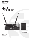
Model UHF-R™ Wireless User Guide
Model UHF-R™ Wireless User Guide
©2005, Shure Incorporated
27NS8849B (Rev. 2)
Printed in U.S.A.
English
! IMPORTANT SAFETY INSTRUCTIONS !
1.
2.
3.
4.
5.
6.
7.
8.
9.
10.
READ these instructions.
KEEP these instructions.
HEED all warnings.
FOLLOW all instructions.
DO NOT use this apparatus near water.
CLEAN ONLY with dry cloth.
DO NOT block any ventilation openings. Install in accordance with the manufacturer's instructions.
DO NOT install near any heat sources such as radiators, heat registers, stoves,
or other apparatus (including amplifiers) that produce heat.
DO NOT defeat the safety purpose of the polarized or grounding-type plug. A
polarized plug has two blades with one wider than the other. A grounding type
plug has two blades and a third grounding prong. The wider blade or the third
prong are provided for your safety. If the provided plug does not fit into your outlet, consult an electrician for replacement of the obsolete outlet.
PROTECT the power cord from being walked on or pinched, particularly at plugs,
convenience receptacles, and the point where they exit from the apparatus.
This symbol indicates that there are important operating and
maintenance instructions in the literature accompanying this unit.
11.
12.
13.
14.
15.
ONLY USE attachments/accessories specified by the manufacturer.
USE only with a cart, stand, tripod, bracket, or table
specified by the manufacturer, or sold with the
apparatus. When a cart is used, use caution when
moving the cart/apparatus combination to avoid
injury from tip-over.
UNPLUG this apparatus during lightning storms or when unused for long periods of
time.
REFER all servicing to qualified service personnel. Servicing is required when the
apparatus has been damaged in any way, such as power-supply cord or plug is damaged, liquid has been spilled or objects have fallen into the apparatus, the apparatus
has been exposed to rain or moisture, does not operate normally, or has been
dropped.
DO NOT expose the apparatus to dripping and splashing. DO NOT put objects filled
with liquids, such as vases, on the apparatus.
This symbol indicates that dangerous voltage constituting a
risk of electric shock is present within this unit.
WARNING: Voltages in this equipment are hazardous to life. No user-serviceable parts inside. Refer all servicing to qualified service personnel. The
safety certifications do not apply when the operating voltage is changed from the factory setting.
3
English
Contents
Important Safety Instructions . . . . . . . . . . . . . . . . . . . . . . . . . . . . . . . . . . . . . . . . . . . . . . 3
Feature Overview . . . . . . . . . . . . . . . . . . . . . . . . . . . . . . . . . . . . . . . . . . . . . . . . . . . . . . 6
System Components . . . . . . . . . . . . . . . . . . . . . . . . . . . . . . . . . . . . . . . . . . . . . . . . . . . . 7
Receiver Controls and Connectors . . . . . . . . . . . . . . . . . . . . . . . . . . . . . . . . . . . . . . . . . 8
Receiver LCD Interface . . . . . . . . . . . . . . . . . . . . . . . . . . . . . . . . . . . . . . . . . . . . . . . . . . 9
Receiver Parameters . . . . . . . . . . . . . . . . . . . . . . . . . . . . . . . . . . . . . . . . . . . . . . . . . . . . 9
Automatic Frequency Selection . . . . . . . . . . . . . . . . . . . . . . . . . . . . . . . . . . . . . . . . . . . 11
Networking Receivers . . . . . . . . . . . . . . . . . . . . . . . . . . . . . . . . . . . . . . . . . . . . . . . . . . 12
Handheld and Bodypack Transmitter Controls and Connectors . . . . . . . . . . . . . . . . . . 13
Transmitter LCD Interface . . . . . . . . . . . . . . . . . . . . . . . . . . . . . . . . . . . . . . . . . . . . . . . 13
Transmitter Batteries . . . . . . . . . . . . . . . . . . . . . . . . . . . . . . . . . . . . . . . . . . . . . . . . . . . 13
Transmitter Parameters . . . . . . . . . . . . . . . . . . . . . . . . . . . . . . . . . . . . . . . . . . . . . . . . . 14
Setting Transmitter Gain . . . . . . . . . . . . . . . . . . . . . . . . . . . . . . . . . . . . . . . . . . . . . . . . 14
RF Safety Mode . . . . . . . . . . . . . . . . . . . . . . . . . . . . . . . . . . . . . . . . . . . . . . . . . . . . . . 14
Automatic Transmitter Sync . . . . . . . . . . . . . . . . . . . . . . . . . . . . . . . . . . . . . . . . . . . . . 15
Troubleshooting . . . . . . . . . . . . . . . . . . . . . . . . . . . . . . . . . . . . . . . . . . . . . . . . . . . . . . . 16
Specifications . . . . . . . . . . . . . . . . . . . . . . . . . . . . . . . . . . . . . . . . . . . . . . . . . . . . . . . . 17
Replacement Parts and Accessories . . . . . . . . . . . . . . . . . . . . . . . . . . . . . . . . . . . . . . 19
UHF-R Wireless System Compatibility Guide . . . . . . . . . . . . . . . . . . . . . . . . . . . . . . . . 69
5
Shure UHF-R Wireless
Feature Overview
The UHF-R™ Wireless Microphone System uses the latest wireless technology, delivers outstanding audio clarity, and is rugged and
reliable. It is easy to set up and operate with advanced features for professional installations requiring multiple wireless microphone
systems.
Frequency Band Selection
Shure offers wireless systems in a selection of bands that conform to the different government regulations of specific nations or geographic regions. These regulations help limit radio frequency (RF) interference among different wireless devices and prevent interference with local public communications channels, such as television and emergency broadcasts.
The system’s band and frequency range are identified on the face of the receiver and transmitter. For example, “H4 518–578 MHz.”
For information on bands available in your area, consult your local dealer or phone Shure. More information is also available at Shure’s
website (www.shure.com).
Groups and Channels
To transmit audio through a wireless system, the transmitter and receiver must be set to the same radio frequency, or channel. A wide
selection of channels allows more microphones to be used at the same time, since each microphone must operate on a different channel. It also provides a greater choice of open channels—those that are free from interference from television broadcasts, electronic
devices, or other wireless systems.
A group is a selection of compatible channels. Wireless microphones work better together when set to channels in the same group.
Automatic Frequency Selection
The following features scan the RF environment to find the best group and channel settings for a particular installation.
• Group Scan—finds the group with the most open channels, then sets all networked receivers to channels in that group.
• Channel Scan—finds the first open channel in the currently selected group and sets the receiver to that channel.
Follow the steps on page 11 for instructions on using these features.
Automatic Transmitter Sync
This feature automatically transfers the group and channel settings from a receiver to a transmitter. You can also program other transmitter settings on a receiver and transfer those settings too. See page 15.
Interface Lock
This feature locks the receiver and transmitters so that users cannot change settings. The transmitter power switch can also be disabled so that the transmitter remains on if the power switch is accidentally toggled during a performance.
Audio Gain Structure
The following settings allow you to adjust audio gain throughout the system:
• Sensitivity (bodypack only). A 25 dB range of gain adjustment at the bodypack transmitter input.
• Transmitter Gain. A 30dB range of audio gain adjustment within the transmitter (affects audio level at the receiver, as indicated by
the Audio LEDS.)
• Output Level. 32 dB of attenuation at the receiver output, plus a mute setting.
• Mic/Line switch. –30 dB pad for matching audio levels at the receiver XLR output.
Networking
Each receiver has an RJ-45 port on the back for connecting to other receivers over an Ethernet network. Networking receivers allows
you to automatically set channels for all the receivers with a single group scan command. You can also control and monitor all networked receivers through the Shure Wireless Workbench PC software.
Shure Wireless Workbench Software
The Shure Wireless Workbench software on the supplied CD includes a variety of useful tools for installing and managing multiple
wireless systems. Simply install the software on your computer and connect it to a network of receivers to monitor and control receivers
and transmitters throughout the network. (See page 12 for more information on networking.)
Instructions on using the Wireless Workbench software are available in the online help files after you install the software.
6
English
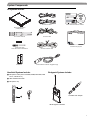
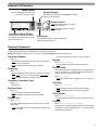
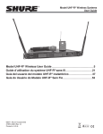
System Components
All systems include:
Two Antenna Cables
Shure’s Wireless Workbench Software
UR4S or UR4D Receiver
(UR4D pictured)
IEC Power Cable
Two 1/2 Wave Antennas
Transmitter Carrying Case
2 Antenna hole plugs
4 Rack Mount Screws with Washers
IEC Power Extension Cable
AA Batteries
Ethernet Network Cable with “Ruggedized” plug
Bodypack Systems Include:
Handheld Systems Include:
쐃 Microphone Head (choice of
87A™, or Beta 87C™)
SM58®,
SM86, Beta
58A®,
Beta
쐇 UR2 handheld transmitter
쐋 Microphone clip
쐃
쐇
Threaded TA4F Adapter
쐋
UR1 Bodypack Transmitter
7
Shure UHF-R Wireless
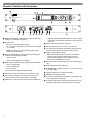
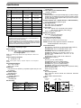
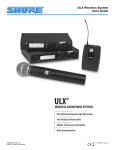
Receiver Controls and Connectors
18
17
2
4
5
RF
Audio
XX YYY-ZZZ MHz
Navigate
Monitor
Control
POWER
OFF
UR4S
Wireless Receiver
with Audio Reference Conpanding
ENTER
OL
3
sync
push
Monitor Clip
EXIT
A
push
B
�
6
antenna B in
receiver outputs
balanced low Z
7
networking
8
antenna A in
200Ω
network
activity
line
12.7V
out
mic
150mA
9
10
11
12
lift
GND
13
14
ethernet
RJ-45
15
쐃 SYNC Infrared (IR) port. Transmits group, channel, and other
settings to a transmitter. See page 15.
쐇 Squelch LEDs.
17
11
• Monitor Clip LED indicates headphone audio is clipping.
• Dual models: Push the knob to switch from receiver one to receiver two.
• Blue (On) = Transmitter signal detected
쐊 Power switch. Powers the unit on and off.
• Off = no signal or signal squelched because of poor reception
or no tonekey
쐎 AC mains power input, IEC connector. 100–240 Vac.
NOTE: The receiver will not output audio unless at least
one blue LED is illuminated.
쐋 RF LEDs. Indicate RF signal strength from the transmitter at
each antenna and diversity condition.
• Amber = normal
• Red = overload (greater than –25 dBm)
쐏 Audio LEDs. Indicate audio signal strength from transmitter.
• Green = signal present
• Yellow = normal peak
• Red = overload
To correct this level, adjust the transmitter gain.
쐄 Indicates the name and range of receiver frequency band.
쐂 LCD Interface. Provides a convenient way to program the
receiver from the front panel (see detail on next page).
쐆 Monitor. 1/4” output jack and volume knob for headphones.
8
16
12.7V
out
150mA
쐅 AC mains power passthrough (unswitched). Use with an IEC
extension cable to supply AC power to another device.
쐈 Diversity antenna inputs A and B.
Note: Antenna inputs are DC biased. Use only antenna
combiners and accessories listed in page 19. Some
types of antenna splitters or other products may short
the DC power and damage the receiver.
쐉 Mic/Line switch. Changes output level –30 dB (XLR output
only).
씈 Electrically balanced XLR output jack
씉 Lift/GND switch. Lifts ground from Pin 1 of the XLR connector (default = GND).
씊 Impedance balanced 1/4” output jack (200Ω)
씋 USB jack for computer interface.
씌 RJ-45 jack for Ethernet network interface. Accepts both regular and “ruggedized” RJ-45 plugs.
씍 Temperature-activated fan ensures top performance in high
temperature environments. Clean fan screen as needed to
English
Receiver LCD Interface
Menu Access
Press the Navigate key next to the
menu item you want to select.
SHURE
Radio
524-025 MHz TV: 32
Audio
G: 3 Ch: 1 Out: -0dB
Util
+ +12 dB
Hi
Accept Changes
After changing a parameter, the ENTER button flashes.
Press it to save the value.
Cursor Control
Push the Control wheel to move the
cursor to the next item.
Turn the Control wheel to change a
parameter value.
F, P, FP Sync
Transmitter Status Display
Everything under the dotted line reflects
the settings for the transmitter, if present.
(main title screen only).
Exit/Cancel
Press the Exit button to cancel changes and
return to the previous menu.
Receiver Parameters
Use the following instructions to set parameters through the LCD interface.
NOTE: After adjusting a parameter, you must press the flashing ENTER button to accept the change.
Group and Channel
Menu: Radio
• Push the Control wheel to move the cursor to the Group (G)
or Channel (Ch) parameter.
• Turn the Control wheel to change the parameter.
Frequency
Menu: Radio
• Push the Control wheel to move the cursor to the integer
value (741.000 MHz) or fractional value (741.025).
• Turn the Control wheel to change the value.
Automatic Transmitter Sync
Menu: Sync
• See page 15.
Receiver Name
Menu: Util
• Turn the Control wheel to change the letter.
• Push the Control wheel to move to the next letter.
Output Level
Menu: Audio
This setting adjusts the signal level at the XLR and 1/4” audio
output jacks.
• Turn the Control wheel to change the relative level in dB.
(0 dB to –32 dB).
• Turn the wheel all the way down to mute the outputs.
Squelch
Menu: Radio > Squelch
• Turn the Control wheel to change the parameter
Receiver Lock
When locked, the receiver settings cannot be changed from the
front panel. However, you can still navigate the LCD menu to
view the settings (and turn the lock off).
Menu: Util > Lock
• Turn the Control wheel to toggle the lock on or off (ON or
OFF).
LCD View
Menu: Util > Title
• Turn the Control wheel to mark an item for display.
• Push the Control wheel to move to the next item.
LCD Contrast
Menu: Util > Contrast
• Turn the Control wheel to increase or decrease contrast.
Tonekey
Menu: Radio > Squelch > Tonekey
Tonekey squelch mutes the outputs unless the receiver detects
a transmitter. Tonekey should be left on (On) except for certain
troubleshooting operations.
9
Shure UHF-R Wireless
Network Parameters
NOTE:
• The receiver reboots after you press ENTER to accept network parameter changes
• In dual models (UR4D), these settings affect both receivers
(the dual receiver is treated as a single network device).
Set the Receiver Network Mode
Menu: Util > Network
1. Push the Control wheel to move the cursor to the Mode
parameter.
2. Turn the Control wheel to set the receiver to one of the
following values:
• DHCP: use this setting when connecting the receiver to a
DHCP server.
• Manual: allows you to set the receiver to a specific IP address or subnet.
IP Address and Subnet
Menu: Util > Network
NOTE: To change these settings, the network mode must be
set to Manual.
1. Push the Control wheel to move the cursor to any of the
following parameters:
• IP (IP address)
• Sub (Subnet mask)
2. Turn the Control wheel to change the value.
Device ID
Assists in identifying receivers through the Wireless Workbench Software (has no effect on network identification).
Menu: Util > Network
1. Push the Control wheel to move the cursor to the
DevID parameter.
2. Turn the Control wheel to set the receiver to change the
value.
Custom Groups
This feature allows you to create your own groups of
frequencies.
Creating new groups...
Menu: Radio > Custom
1. Turn the Control wheel to select a custom group number
(U1, U2, U3, etc.)
2. Push the Control wheel to move to the
10
English
Automatic Frequency Selection
Follow these steps to use the channel scan and group scan features.
Before you begin...
• Install the receivers in the location where they will be used and power them on.
• Mute all inputs on mixing devices connected to receivers.
• Turn off all bodypack or handheld transmitters for the systems you are setting up.
• Turn on potential sources of interference such as other wireless systems or devices, computers, CD players, effects processors, and
digital rack equipment so they are operating as they would be during the presentation or performance.
Single Receiver
1.
2.
3.
4.
5.
Select Radio > Scan > Chan Scan using the Navigate keys on the receiver LCD interface.
Turn the Control wheel to select a group.
Press Chan Scan. The display indicates that the receiver is searching. Once it has finished, it displays the selected channel.
Press the flashing ENTER button to accept the suggested channel.
Sync the transmitter (see page 15).
Networked or Dual Receivers
With networked or dual receivers, you can take advantage of the group scan feature to set group and channel settings for all the receivers at the same time. (See page 12 for instructions on networking.)
Perform a group scan from any receiver...
1. Select Radio > Scan > Group Scan using the Navigate keys on the receiver LCD interface. The display indicates that
the receiver is searching (Scan In Progress). Once it has finished, it displays the group with the most open channels.
2. If you wish, turn the Control wheel to change groups. The number of open channels for each group is displayed.
3. Press the flashing ENTER button to set all receivers to open channels in that group.
NOTE: The group scan feature only works for receivers in the same frequency band. For example, if you did a group scan on a
“H4” band receiver, all “H4” band receivers would be set up, but not “J5” band receivers.
Multiple Receivers—Not Networked
If your receivers are not networked (or in different bands), the group scan cannot automatically set their group and channel settings.
However, you can still take advantage of the group scan feature to find the group with the most open channels and the channel scan
feature to find open channels in that group.
Find the group with the most open channels...
Perform a group scan using the steps for a networked receiver (above). However, make a note of the selected group before pressing
the flashing ENTER button to accept it.
Set the receivers to open channels in that group...
Perform a channel scan on the remaining receivers using the steps for a single receiver (above). Make sure to select the same group
for each receiver before performing the channel scan.
IMPORTANT: After setting the channel for the first receiver, immediately sync the transmitter for that receiver and leave it on so
that the next receiver detects that channel during its channel scan. Otherwise, all the receivers will be set to the same open
channel.
NOTE: Receivers in different bands (H4, J5, L3, etc.) do not need to be set to the same group.
11
Shure UHF-R Wireless
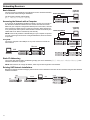
Networking Receivers
Basic Network
Connect receivers to an Ethernet router with DHCP service. Use Ethernet switches to extend the network for larger installations.
Computer
(optional)
Router with DHCP
Use the receiver’s default network setting
(Util > Network > Mode = DHCP).
Accessing the Network with a Computer
If you want to use the Wireless Workbench software, connect your computer to
the network and install the software from the CD that came with the receiver.
Make sure your computer is configured for DHCP (from Control Panel, click Network Connections. Double-click on Local Area Connection. Select Internet Protocol (TCP/IP) and click Properties. Select Obtain IP address automatically and
Obtain DNS server address automatically and click OK).
Computer
(optional)
Router with DHCP
NOTE: Some security software or firewall settings on your computer can prevent
you from connecting to the receivers. If using firewall software, allow connections
on port 2201.
Switch
Using USB...
Connect the computer to the USB port on any of the receivers to access the
whole network.
Ethernet
Switch
USB
Static IP Addressing
The receiver also supports static IP addressing. Assign your own IP addresses ( Util > Network > Mode = Manual). See
“Network Parameters” on page 10.
NOTE: Dual receivers use a single IP address, which may be set through either LCD interface.
Existing UHF Network Installations
Both Shure’s UHF-R receivers and legacy UHF receivers can be networked to the same PC and accessed using the latest Wireless
Workbench software.
U888
UHF
12
RS-232
USB
UHF-R
English
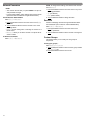
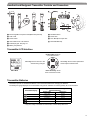
Handheld and Bodypack Transmitter Controls and Connectors
쐆
�
쐊
쐋
�
쐅
쐇
�
�
쐎
�
�
쐏
쐄
쐂
쐃 Interchangeable microphone head (BETA 87A pictured).
쐆 Flexible Antenna.
쐇 LCD Panel.
쐊 Power LED.
쐋 Power Switch.
쐎 4-Pin Microphone Input Jack.
쐏 Control buttons for LCD interface.
쐅 Reversible Belt Clip.
쐄 Infrared (IR) port. See page 15.
쐂 Battery compartment.
Transmitter LCD Interface
Up Arrow Key. Scroll up
or increase a value.
779.475MHz
exit Key. Move to the left, or exit
without saving changes.
enter Key. Press to select parameters
and accept the selected value.
Down Arrow Key. Scroll
down or decrease a value.
Main Menu
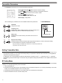
Transmitter Batteries
Transmitters operate on standard AA batteries. Turn off the transmitter before changing the batteries.
The battery fuel gauge displayed on the transmitter LCD gives an indication of remaining battery life, as shown below.
Transmitter Display
Approximate Hours Remaining
(alkaline batteries)
Normal Power
High Power*
7.5 to 9.5
5.75 to 7.5
4 to 5.75
2 to 4
15 minutes to 2 hours
5 to 6
4 to 5
3 to 4
1.5 to 3
10 minutes to 1.5
* High power setting not available with models sold in countries that prohibit its use.
13
Shure UHF-R Wireless
Transmitter Parameters
Press ENTER from the main menu to access the following parameters:
G:34 Ch:21
Group (G) and Channel (Ch). Must match the receiver’s settings.
Frequency (MHz). Manual frequency selection in 0.025 MHz increments.
779.475MHZ
Gain (Gain). Adjusts audio level from –10 dB to +20 dB.
Gain +20dB
Sensitivity (Sens) (bodypack only).
Sets audio input to +15 dB, 0 dB, or –10 dB.
SHURE INC.
Name Display. 12-digit ASCII.
Use the following key combinations to access additional features and parameters:
hold
tap
LCD Panel
Changes LCD Panel
hold
tap
Frequency Lock
Toggles setting. When enabled, frequency cannot be changed, and a
transmitter sync will not overwrite the frequency setting.
Lock Indicators
Power Lock
hold
tap
Power Lock
Toggles power lock. When locked, power switch does not turn off
transmitter.
hold
hold
RF power level setting*
Use the arrow keys to select normal (10 mW) or high power (50/100 mW**). Use the normal power setting
to conserve batteries or prevent RF overload at the receiver.
Frequency Lock
* High power setting not available with models sold in countries that prohibit its use.
** High power value varies with model.
Setting Transmitter Gain
Adjust the transmitter gain and input sensitivity so that the Audio LEDs on the receiver peak within the yellow range during use. On
the bodypack transmitter, you can change the sensitivity setting to compensate for different audio levels when connecting different
intruments or microphones to the input.
To adjust gain, turn on the transmitter and press the enter button. Scroll down to the Gain parameter or the Sens parameter
(bodypack only) and press enter again. Use the arrow keys to adjust the setting and press enter to save it (Exit cancels without
saving).
RF Safety Mode
This special feature temporarily mutes RF broadcast. This allows you to change frequency settings on a transmitter without accidentally
“cutting in” on a channel being used by another transmitter.
1. Turn the transmitter off.
2. Hold down exit key while turning on the transmitter power (for handheld microphones, you need to pull the battery cover off the
handle). The LCD flashes while the unit is in RF safety mode.
3. Change group and channel settings as you normally would—the transmitter will not broadcast.
4. Power the transmitter off and on to exit RF safety mode.
14
English
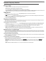
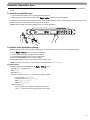
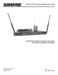
Automatic Transmitter Sync
This feature automatically updates a bodypack or handheld transmitter’s group and channel settings to match those of a selected
receiver.
To perform a transmitter sync...
1. Open the transmitter battery cover to display the infrared (IR) port.
2. With the IR port exposed to the receiver, select Sync > sync from the receiver LCD interface.
The display on the receiver indicates whether the sync was successful. If the sync fails, try again, making sure that the IR port on the
transmitter is exposed and directly faces the IR port on the receiver.
NOTE: Close the battery door before performing a sync on other transmitters.
®
RF
Audio
ABJ
779-810 MHz
Navigate
RF
Audio
ABJ
779-810 MHz
Navigate
Monitor
Control
Power
1
OL
OL
ENTER
2
push
UR4D
Monitor Clip
Wireless Receiver
with Audio Reference
Companding
EXIT
sync
sync
To transfer other transmitter settings...
Optionally, you can transfer other transmitter settings from a receiver when you perform a sync. Use the following steps:
1. Select Sync > Setup from the receiver LCD interface.
2. Turn the Control wheel to change parameter settings.
3. Push the Control wheel to move to the next parameter.
4. Push the flashing ENTER button to save the settings.
The transmitter settings you set on the receiver remain for future syncs.
NOTE: If you don’t want the sync to send a setting, set the parameter to No Change
Available Settings...
The following settings are available from the Sync > Setup menu:
• Sensitivity (Sens) bodypack only
• Gain (Gain)
• RF Power (Pwr)
• Power and Frequency Lock (Lock), which has the following values:
Power lock only: (Pwr Only)
Frequency lock only: (Freq only)
Both: (Freq and Pwr)
Neither: (Unlocked)
• Custom Groups (CG):
On (ON): Send custom groups to transmitters during sync
Off (OFF): Do not send custom groups (reduces sync time)
15
Shure UHF-R Wireless
Troubleshooting
Issue
No sound
Faint Sound or Distortion
Lack of range, unwanted noise bursts, or
drop outs
Cannot turn transmitter off or change frequency
settings, or can’t program receiver
Excessive hum or buzzing
See Solution...
Power, Cables, or RF
Gain
RF
Interface Locks
Ground lift
Power
Make sure that the transmitter and receiver are receiving
sufficient voltage. The receiver requires at least 90 Vac. Check
the battery indicator on the transmitter and replace battery if
necessary.
Gain
Adjust the transmitter gain and sensitivity settings
(see page 14) or the receiver output level (page 9), or toggle
the mic/line switch on the back of the receiver.
Cables
Check that all cables and connectors are in working order.
Ground Lift
Lifting the ground on pin 1 of the XLR output on the receiver
can sometimes remove hum or buzz in the audio signal. Set the
GND/LIFT switch on the receiver to LIFT if you are using the
XLR connector.
Interface Locks
Both the transmitter and receiver can be locked to prevent accidental changes. On transmitters, look for a lock symbol on the
LCD and use the key combinations illustrated on page 14 to
turn it off.
To turn off the receiver interface lock, see page 9.
Radio Frequency (RF)
Using the RF LEDs
If neither blue RF LED is illuminated, then the receiver is not detecting the presence of a transmitter.
The amber RF LEDs indicate the amount of signal being received. This signal could be from the transmitter, or it could be
from an interfering source, such as a television broadcast. Turn
the transmitter off. If more than one or two of the amber RF
LEDs are still illuminated, then that channel has too much interference, and you should try a different channel.
The red RF LED indicates RF overload. This will usually not
cause a problem unless you are using more than one system
at the same time, in which case, it can cause interference between systems.
16
Compatibility
• Perform a transmitter sync, or make sure the transmitter and
receiver are set to the same group and channel.
• Look at the label on the transmitter and receiver to make sure
they are in the same band (H4, J5, L3, etc...).
Reducing Interference
• Use a different channel or perform an automatic group or
channel scan (see page 11).
• For multiple systems, check that all systems are set to channels in the same group (systems in different bands do not
need to be set to the same group).
• Maintain a line of sight between transmitter and receiver antennas
• Move receiver antennas away from metal objects or other
sources of RF interference (such as CD players, computers,
digital effects, network switches, network cables and Personal Stereo Monitor (PSM) wireless systems).
• Eliminate RF overload (see below).
Increasing Range
If the transmitter is more than 6 to 60 m (20 to 200 ft) from the
receiver antenna, you may be able to increase range by doing
one of the following:
• Reduce interference (see above)
• Increase transmitter RF power level (see page 14).
• Use an active directional antenna, antenna distribution system, or other antenna accessory to increase RF range (see
page 19).
Eliminating RF Overload
If you see the red RF LED on a receiver, reduce the transmitter
RF power level (see page 14) or move the transmitter further
away from the receiver—at least 6 m (20 ft). If you are using active antennas, reduce antenna or amplifier gain.
English
Specifications
Frequency Range and Transmitter Output Power
Band
Range
H4E,
H4
J5E,
J5
L3E,
L3
Q5
R9
Q6
A24
518-578 MHz
Transmitter power (mW)
Handheld
Bodypack
10 / 50
10 / 50
10 / 50
10 / 100
578-638 MHz
(578-608, 614-638)
10 / 50
10 / 50
10 / 50
10 / 100
638-698 MHz
10 / 50
10 / 50
10 / 50
10 / 100
740-814 MHz
790-865
740-752 MHz
779-788 / 797-806
MHz
JBX 806-810 MHZ
Q10 740-798 MHz
10 / 50
10 / 50
10
10
10 / 50
10 / 50
10
10
10
10 / 50
10
10 / 50
NOTE
This Radio equipment is intended for use in musical professional
entertainment and similar applications.
This Radio apparatus may be capable of operating on some frequencies not authorized in your region. Please contact your national
authority to obtain information on authorized frequencies and RF
power levels for wireless microphone products.
RF Carrier Frequency Range
518-865 MHz, depending on region
Working Range
UR1, UR2: 150 m (500 ft.), under typical conditions
500 m (1600 ft) line-of-sight, outdoors
for a single system
NOTE: Actual working range depends on RF signal absorption, reflection and
interference
Audio Frequency Response
40 – 18,000 Hz, ±1 dB.
NOTE: Overall system frequency response depends on the microphone
element
Gain Adjustment Range
UR1: –20 to +35 dB
UR2: –10 to +20 dB
Modulation
FM (45 kHz max. deviation), compander system with pre- and
de-emphasis
RF Power Output
See table above.
Dynamic Range
>105 dB, A-weighted
Image Rejection
>110 dB typical
RF Sensitivity
Spurious Rejection
>90 dB typical
Ultimate Quieting (ref. 45 kHz deviation)
>100 dB, A-weighted
Signal Polarity
Positive pressure on microphone diaphragm (or positive voltage
applied to tip of WA302 phone plug) produces positive voltage
on XLR output pin 2 with respect to XLR pin 3 and on the tip of
the 1/4-inch output jack.
System Distortion (ref. ± 45 kHz deviation, 1 kHz modulation)
<0.3% Total Harmonic Distortion typical
Power Requirements
UR1, UR2: Two 1.5V AA batteries
UR4:100 to 240 Vac, 50/60 Hz
Current Drain
UR1, UR2: 180 mA max. (normal RF power setting)
240 mA max. (high RF power setting)
UR4D, UR4S: 0.8 Amps max.
Battery Life (Typical)
UR1, UR2: 9.5 hours (low power)
6 hours (high power)
Operating Temperature Range
–18° to +57° C (0° to +135° F)
NOTE: Battery characteristics may limit this range
NOTE: Electrical safety approval is based on a maximum
ambient temperature of 35°C (95°F).
Overall Dimensions
UR1: 98 mm L x 60 mm W x 17 mm D (3.84 x 2.38 x 0.66 in.)
UR2/SM58: 261 mm L x 51 mm Dia. (10.27 x 2 in.)
UR2/SM86: 261 mm L x 51 mm Dia. (10.27 x 2 in.)
UR2/SM87A: 254 mm x 51 mm Dia. (10 x 2 in.)
UR2/BETA 58: 258 mm L x 51 mm Dia. (10.15 x 2 in.)
UR2/BETA 87A, UR2/BETA 87C: 254 mm x 51 mm
Dia. (10 x 2 in.)
UR4S/UR4D: 44 mm H x 483 mm W x 366 mm D
(1.72 x 19.00 x 14.39 in.)
Net Weight
UR1: 97 g (3.4 oz.) without battery
UR2/SM58: 356 g (12.6 oz.) without battery
UR2/BETA 58: 314 g (11.1oz.) without battery
UR2/SM86: 317 g (11.2 oz.) without battery
UR2/SM87A: 298 g (10.5 oz.) without battery
UR2/BETA 87A, U2/BETA 87C: 325 g (11.5 oz) without battery
UR4S: 4.8 kg (10.6 lbs)
UR4D: 5.0 kg (11.0 lbs)
Housing:
UR1: Cast magnesium
UR2: Aluminum die-cast handle and aluminum machined
battery cup
UR4S, UR4D: Galvanized steel
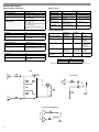
Wiring
MICROPHONE
ELEMENT
TA4F
Connector
TA4M
Connector
UR1 MIC JACK BOARD
UR4S
UR4D
–110 dBm Typical
12 dB SINAD
–107 dBm Typical
12 dB SINAD
–105 dBm Typical
30 dB SINAD
–102 dBm Typical
30 dB SINAD
Active Load
Audio
Ground
NOTE: LAVALIER MIC TIES PINS 3 AND 4 TOGETHER—GUITAR CABLE DOES NOT.
17
Shure UHF-R Wireless
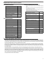
Inputs and Outputs
UR1 Transmitter Audio Input
Receiver Input
Connector:
4-Pin male mini connector (TA4M)
Antenna
Power
Input Configuration:
Unbalanced, active
Connector Type:
BNC
IEC
Actual Impedance:
>1 MΩ
Actual Impedance:
50 Ω
-
Maximum Input Level:
+10 dBu (unpadded)
+20 dBu (padded)
Nominal Input Level:
–95 to –30 dBm
100-240 VAC,50/60 Hz
Maximum Input
Level:
–20 dBm
240 VAC, + 10%, 50/60 Hz
Pin Assignments:
Shell = Ground
Center = Signal
IEC Standard
Bias Voltage*
12.2 Vdc @ 150 mA
maximum
N/A
TA4M Connector
Pin Assignments:
Pin 1: Ground
Pin 2: +5 Vdc bias
Pin 3: Audio
Pin 4: Tied through active load (on main
board) to Ground.
(On instrument adapter cable, Pin 4
floats)
UR1 Transmitter RF Output
* For remote antenna amplifiers
Receiver Audio Output
Connector:
SMA
Actual Impedance:
50 Ω
Pin Assignments:
Shell = Ground
Center = Signal
UR2 Transmitter Audio Input
Input Configuration:
Unbalanced, active
Actual Impedance:
>1 MΩ
Maximum Input Level:
3 Vp-p (0.5 dBV) for 1% THD at
minimum gain setting using 1 kHz
signal.
Monitor (1/4”
Headphone)
1/4” Phone
XLR
Output Configuration:
Unbalanced
mono, 1/4 inch
Impedance
Balanced
Electrically
Balanced
Actual Impedance:
50 Ω
200 Ω
200 Ω (active
balanced)
(150 Ω mic)
Maximum Output Level
1 Watt @ 63 Ω
+18 dBu
+24 dBu
(–6 dBu mic)
with 100 Hz
modulating tone
Pin Assignments:
Tip = Hot
Ring = Hot
Sleeve = Gnd
Tip = Hot
1 = Ground
Ring = no signal 2 = Audio +
Sleeve = Gnd
3 = Audio –
Phantom Power
Protection?
No
Yes
UR2 Transmitter RF Output
Connector:
SMA
Actual Impedance:
50 Ω
Pin Assignments:
Shell = Ground
Center = Signal
Yes
Computer/Network Interface
Ethernet
USB*
RJ45
USB Series B Receptacle
* USB-IF logo is a trademark of Universal Serial Bus Implementers Forum, Inc.
XLR
1/4” Phone
1/4” Monitor/headphone
18
English
Replacement Parts and Accessories
Furnished Accessories
Antenna Combiners and Accessories
Microphone Stand Adapter (UR2)
WA371
Zipper Bag (UR1)
26A13
Zipper Bag (UR2)
26A14
Antenna Extension Cables (2)
95A9023
Hardware Kit, Locking Connector
WA340
Antenna (UR1), 518-578 MHz
UA710
Antenna (UR1), 578-698 MHz
UA720
Antenna (UR1), 740-865 MHz
UA730
Two Antennas (UR4), Band
Dependent (see table)
UA820
Transmitter Carrying Case
• Antennas and receivers must be from the same frequency
band.
• The supplied 1/2 wave antennas can be remotely mounted or
mounted directly to the UA845.
• Antennas and cables for use with the UA845 can also be
used with stand-alone UHF-R receivers.
Passive Antenna/Splitter Combiner Kit
(recommended for 2 receivers)
UA221
UHF Antenna Power Distribution Amplifier
(recommended for 3 or more receivers)
UA845-
95A9053
U.S.A.
UA845US
Europe
UA845E
UK
Optional Accessories
UA845UK
SM58 Head with Grille
RPW112
1/2 Wave, Omnidirectional, Wideband
Antenna
SM86 Head with Grille
RPW114
Active Directional Wideband Antenna
UA870WB
BETA 58 Head with Grille
RPW118
Wideband In-Line RF Amplifier
UA830WB
BETA 87A Head with Grille
RPW120
Passive Unidirectional Wideband Antenna
PA805WB
BETA 87C Head with Grille
RPW122
1/2 wave antennas (2)
SM87A Head with Grille
RPW116
H4E, H4 Bands
RK143G
J5E, J5 Bands
UA820J
RPM266
L3E, L3 Bands
UA820L3
RK265G
Q5, Q6, Q10 Bands
UA820Q
Black Grille (SM87)
RK214G
R9, ABJ Bands
UA820A
Matte Silver Grille (BETA 87A)
RK312
25’ Antenna Cable (RG-8/X)
UA825
Matte Silver Grille (BETA 87C)
RK312
50’ Antenna Cable (RG-8/X)
UA850
Black Grille (BETA 58)
RK323G
100’ Antenna Cable
UA8100
Matte Silver Grille (SM58)
Matte Silver Grille (SM86)
Matte Silver Grille (BETA 58)
Black Grille (BETA 87A/BETA 87C)
RK324G
Belt Clip
44A8031
Body-Pack Pouch (Black), UR1
WA580B
Body-Pack Pouch (White), UR1
WA580W
UA860WB
UA820H4
Architects' and Engineers' Specifications
The wireless system shall operate in the UHF band between 518 MHz and 865 MHz, with the specific range being dependent on the
user's locale. The system shall include the option of changing the operating frequency in order to avoid RF interference, enabling up
to 108 systems to operate simultaneously in the same location. Preconfigured group, channel and frequency setups shall be available
to ensure that multiple systems in use do not interfere with one another.
All transmitters shall be powered by 2 AA batteries and shall have a power on/off switch. The bodypack will have an LED indicating
that power is on. Available transmitters shall include: a body pack for use with electric guitars, basses, and other electric instruments,
and a handheld microphone for vocals. The transmitters shall have a DC/DC converter to ensure consistent performance, even if battery voltages change.
The receiver shall have a user-programmable, menu-driven LCD showing group, channel, frequency, name, squelch level, and
locked/unlocked status. The system shall use technology such as MARCAD signal combining circuitry to improve reception, minimize
signal dropouts, and achieve the best possible signal-to-noise ratio. An equalizer, tone key squelch, and noise squelch circuitry shall
be built into the system to provide optimal sound quality and minimize unwanted noise. The receiver shall include dual RF meters (one
for each antenna), an audio level meter, and a Networking Interface connector for computer control and monitoring. The receiver shall
have a volume control and an adjustable noise squelch control.
The system shall be the Shure UHF-R Wireless.
19
Shure UHF-R Wireless
Certification
UR1, UR2: Type Accepted under FCC Parts 74 (FCC ID: "DD4UR1" & "DD4UR2"). Certified by IC in Canada under RSS-123 and RSS102 ("IC: 616A-UR1" and "IC: 616A-UR2"). Meets the essential requirements of the European R&TTE Directive 99/5/EC (ETSI EN 300422 Parts 1 & 2, EN 301 489 Parts 1 & 9) and is eligible to carry the CE marking.
UR4S, UR4D: Authorized under the Declaration Of Conformity provision of FCC Part 15. Certified under Industry Canada to RSS-123
("IC: 616A-UR4"). Meets the essential requirements of the European R&TTE Directive 99/5/EC (EN 301 489 Parts 1 & 9, EN 300 422
Parts 1 and 2). Eligible to carry the CE marking.
Conforms to Australian EMC requirements and is eligible for C-Tick marking.
N108
Have been granted the following Country Safety Approvals:
cULus Mark for US and Canada: Meets UL6500 and CSA/CAN E60065. UL GS-Certified to EN60065.
LICENSING INFORMATION:
Licensing: A ministerial license to operate this equipment may be required in certain areas. Consult your national authority for possible
requirements.
Changes or modifications not expressly approved by Shure Incorporated could void your authority to operate the equipment. Licensing of
Shure wireless microphone equipment is the user's responsibility, and licensability depends on the user's classification and application,
and on the selected frequency. Shure strongly urges the user to contact the appropriate telecommunications authority concerning proper
licensing, and before choosing and ordering frequencies.
Information to User
This equipment has been tested and found to comply with the limits for a Class B digital device, pursuant to Part 15 of the FCC Rules.
These limits are designed to provide reasonable protection against harmful interference in a residential installation. This equipment generates, uses and can radiate radio frequency energy and, if not installed and used in accordance with the instructions, may cause harmful
interference to radio communications. However, there is no guarantee that interference will not occur in a particular installation. If this
equipment does cause harmful interference to radio or television reception, which can be determined by turning the equipment off and on,
the user is encouraged to try to correct the interference by one or more of the following measures:
• Reorient or relocate the receiving antenna.
• Increase the separation between the equipment and receiver.
• Connect the equipment into an outlet on a circuit different from that to which the receiver is connected.
• Consult the dealer or an experienced radio/TV technician for help.
This Class B digital apparatus complies with Canadian ICES-003.
Cet appareil numérique de la classe B est conforme à la norme NMB-003 du Canada.
Operation of this device is subject to the following two conditions: (1) this device may not cause interference, and (2) this device must
accept any interference, including interference that may cause undesired operation of the device.
Note: EMC conformance testing is based on the use of supplied and recommended cable types. The use of other cable types may
degrade EMC performance
SHURE Incorporated http://www.shure.com
United States, Canada, Latin America, Caribbean:
5800 W. Touhy Avenue, Niles, IL 60714-4608, U.S.A.
Phone: 847-600-2000 U.S. Fax: 847-600-1212 Intl Fax: 847-600-6446
Europe, Middle East, Africa:
Shure Europe GmbH, Phone: 49-7131-72140 Fax: 49-7131-721414
Asia, Pacific:
Shure Asia Limited, Phone: 852-2893-4290 Fax: 852-2893-4055
20