1
Qik 2s12v10 User's Guide
© 2001–2012 Pololu Corporation
Qik 2s12v10 User's Guide
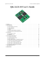
1. Overview . . . . . . . . . . . . . . . . . . . . . . . . .
2. Contacting Pololu . . . . . . . . . . . . . . . . . . . . .
3. Connecting the Qik . . . . . . . . . . . . . . . . . . . .
3.a. Power and Motor Connections . . . . . . . . . .
3.b. Logic Connections . . . . . . . . . . . . . . . .
3.c. Included Hardware . . . . . . . . . . . . . . . .
3.d. Jumpers . . . . . . . . . . . . . . . . . . . . . .
3.e. Indicator LEDs and Phases of Operation . . . . .
3.f. Board Dimensions and Mounting Information . .
4. Serial Interface . . . . . . . . . . . . . . . . . . . . . .
4.a. TTL and RS-232 Serial . . . . . . . . . . . . . .
4.b. Baud Rates . . . . . . . . . . . . . . . . . . . .
4.c. Command Protocols . . . . . . . . . . . . . . . .
5. Serial Parameters and Commands . . . . . . . . . . . .
5.a. Configuration Parameters . . . . . . . . . . . . .
5.b. 0x81: Get Firmware Version . . . . . . . . . . .
5.c. 0x82: Get Error Byte . . . . . . . . . . . . . . .
5.d. 0x83 & 0x84: Get & Set Configuration Parameter
5.e. 0x86 & 0x87: Motor M0 & M1 Variable Brake .
5.f. 0x88 – 0x8F: Set Motor Forward/Reverse . . . .
5.g. 0x90 & 0x91: Get Motor M0 & M1 Current . . .
5.h. 0x92 & 0x93: Get Motor M0 & M1 Speed . . . .
6. Cyclic Redundancy Check (CRC) Error Detection . . .
6.a. CRC Computation in C . . . . . . . . . . . . . .
7. Troubleshooting . . . . . . . . . . . . . . . . . . . . .
8. Arduino Library . . . . . . . . . . . . . . . . . . . . .
http://www.pololu.com/docs/0J29
.
.
.
.
.
.
.
.
.
.
.
.
.
.
.
.
.
.
.
.
.
.
.
.
.
.
.
.
.
.
.
.
.
.
.
.
.
.
.
.
.
.
.
.
.
.
.
.
.
.
.
.
.
.
.
.
.
.
.
.
.
.
.
.
.
.
.
.
.
.
.
.
.
.
.
.
.
.
.
.
.
.
.
.
.
.
.
.
.
.
.
.
.
.
.
.
.
.
.
.
.
.
.
.
.
.
.
.
.
.
.
.
.
.
.
.
.
.
.
.
.
.
.
.
.
.
.
.
.
.
.
.
.
.
.
.
.
.
.
.
.
.
.
.
.
.
.
.
.
.
.
.
.
.
.
.
.
.
.
.
.
.
.
.
.
.
.
.
.
.
.
.
.
.
.
.
.
.
.
.
.
.
.
.
.
.
.
.
.
.
.
.
.
.
.
.
.
.
.
.
.
.
.
.
.
.
.
.
.
.
.
.
.
.
.
.
.
.
.
.
.
.
.
.
.
.
.
.
.
.
.
.
.
.
.
.
.
.
.
.
.
.
.
.
.
.
.
.
.
.
.
.
.
.
.
.
.
.
.
.
.
.
.
.
.
.
.
.
.
.
.
.
.
.
.
.
.
.
.
.
.
.
.
.
.
.
.
.
.
.
.
.
.
.
.
.
.
.
.
.
.
.
.
.
.
.
.
.
.
.
.
.
.
.
.
.
.
.
.
.
.
.
.
.
.
.
.
.
.
.
.
.
.
.
.
.
.
.
.
.
.
.
.
.
.
.
.
.
.
.
.
.
.
.
.
.
.
.
.
.
.
.
.
.
.
.
.
.
.
.
.
.
.
.
.
.
.
.
.
.
.
.
.
.
.
.
.
.
.
.
.
.
.
.
.
.
.
.
.
.
.
.
.
.
.
.
.
.
.
.
.
.
.
.
.
.
.
.
.
.
.
.
.
.
.
.
.
.
.
.
.
.
.
.
.
.
.
.
.
.
.
.
.
.
.
.
.
.
.
.
.
.
.
.
.
.
.
.
.
.
.
.
.
.
.
.
.
.
.
.
.
.
.
.
.
.
.
.
.
.
.
.
.
.
.
.
.
.
.
.
.
.
.
.
.
.
.
.
.
.
.
.
.
.
.
.
.
.
.
.
.
.
.
.
.
.
.
.
.
.
.
.
.
.
.
.
.
.
.
.
.
.
.
.
.
.
.
.
.
.
.
.
.
.
.
.
.
.
.
.
.
.
.
.
.
.
.
.
.
.
.
.
.
.
.
.
.
.
.
.
.
.
.
.
.
.
.
.
.
.
.
.
.
.
.
.
.
.
.
.
.
.
.
.
.
.
.
.
.
.
.
.
.
.
.
.
.
.
.
.
.
.
.
.
.
.
.
.
.
.
.
.
.
.
.
.
.
.
.
.
.
.
.
.
.
.
.
.
.
.
.
.
.
.
.
.
.
.
.
.
.
.
.
.
.
.
.
.
.
.
.
.
.
.
.
.
.
.
.
.
.
.
.
.
.
.
.
.
.
.
.
.
.
.
.
.
.
.
.
.
.
.
.
.
.
.
.
.
.
.
.
.
2
4
5
6
8
10
11
12
14
15
15
16
16
19
19
23
23
24
25
25
27
27
29
30
32
33
Page 1 of 33
Qik 2s12v10 User's Guide
© 2001–2012 Pololu Corporation
1. Overview
The qik 2s12v10 adds a comprehensive yet easy-to-use, high-power option to Pololu’s line of motor controllers.
The compact board—it’s almost the same size as the dual VNH2SP30 carrier board [http://www.pololu.com/catalog/
product/708] by itself—allows any microcontroller or computer with a serial port to drive two brushed DC motors
with full direction and speed control, providing up to 13 A (continuous) per motor channel and tolerating peaks
as high as 30 A. The improvements over competing products include:
• high-frequency PWM to eliminate switching-induced motor shaft hum or whine
• a robust, high-speed communication protocol with user-configurable error condition response
• visible LEDs and a demo mode to help troubleshoot problematic installations
• reverse power protection on the power supply
Main Features of the Qik 2s12v10
• Simple bidirectional control of two DC brush motors.
• 6 V to 16 V motor supply range.
• 13 A maximum continuous current per motor (30 A peak).
• Logic-level, non-inverted, two-way serial control for easy connection to microcontrollers or robot
controllers.
• RS-232-level, one-way serial control for easy connection to a PC serial port.
• Optional automatic baud rate detection from 1200 bps to 115.2 kbps.
• Seven on-board indicator LEDs (power, status/heartbeat, error indicator, and motor indicators) for
debugging and feedback.
• Error output to make it easier for the main controller to recover from an error condition.
• Jumper-enabled demo mode allowing initial testing without any programming.
• Optional CRC error detection eliminates serial errors caused by noise or software faults.
• Optional motor shutdown on error or serial timeout for additional safety.
Specifications
Motor channels:
2
Operating voltage:
6 – 16 V
Continuous output current per channel:
13 A
Peak output current per channel:
30 A
Auto-detect baud rate range:
1200 – 115,200 bps
Available fixed baud rates:
115,200 bps, 38,400 bps, 9600 bps
Available PWM frequencies:
19.7 kHz, 9.8 kHz, 2.5 kHz, 1.2 kHz, 310 Hz, 150 Hz
Reverse voltage protection?:
Y
Motor driver:
VNH2SP30 x2
1. Overview
Page 2 of 33
Qik 2s12v10 User's Guide
© 2001–2012 Pololu Corporation
Important safety warning
This product is not intended for young children! Younger users should use this product only under adult
supervision. By using this product, you agree not to hold Pololu liable for any injury or damage related to
the use or to the performance of this product. This product is not designed for, and should not be used in,
applications where the malfunction of the product could cause injury or damage. Please take note of these
additional precautions:
• This product contains lead, so follow appropriate handling procedures, such as not licking the product and
washing hands after handling.
• Since the PCB and its components are exposed, take standard precautions to protect this product from
ESD (electrostatic discharge), which could damage the on-board electronics. When handing this product to
another person, first touch their hand with your hand to equalize any charge imbalance between you so that
you don’t discharge through the electronics as the exchange is made.
• Review the instructions carefully before making any electrical connections, and do all wiring while the
power is turned off. Incorrect or reversed wiring could cause an electrical short or unpredictable behavior
that damages this product and the devices it is connected to.
• This product is designed to be connected to motors, which should be operated safely. Wear safety glasses,
gloves, or other protective equipment as appropriate, and avoid dangerous situations such as motors spinning
out of control by designing appropriate safeguards and limits into your projects.
1. Overview
Page 3 of 33
Qik 2s12v10 User's Guide
© 2001–2012 Pololu Corporation
2. Contacting Pololu
You can check the qik 2s12v10 dual serial motor controller page [http://www.pololu.com/catalog/product/1112] for
additional information. We would be delighted to hear from you about any of your projects and about your
experience with the qik motor controller. You can contact us [http://www.pololu.com/contact] directly or post on our
forum [http://forum.pololu.com/]. Tell us what we did well, what we could improve, what you would like to see in
the future, or anything else you would like to say!
2. Contacting Pololu
Page 4 of 33
Qik 2s12v10 User's Guide
© 2001–2012 Pololu Corporation
3. Connecting the Qik
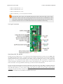
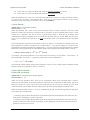
Connecting to the qik can be as simple as hooking up power, your motors, and your serial connections. Many
applications can leave the jumpers off and the remaining logic connections unconnected. The qik’s serial transmit
line, TX, is only necessary if you want to get feedback from the controller.
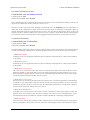
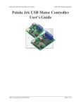
The qik logic and power connections and key components are shown above; the pins are labeled on the back side
of the motor controller. All square pads are ground.
3. Connecting the Qik
Page 5 of 33
Qik 2s12v10 User's Guide
© 2001–2012 Pololu Corporation
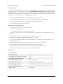
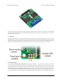
3.a. Power and Motor Connections
Power
The qik motor controller is powered via the large VIN and GND pads on the power side of the board (do not
power the controller through the VIN and GND pads on the logic side of the board!), as shown in the picture
above. The input voltage can be between 6 and 16 V and is the voltage that the motors will see. An integrated
voltage regulator produces the 5 V that powers the board’s logic, so no separate logic power supply is necessary.
Both the input voltage and regulated voltage can be accessed as outputs on the left side of the board (i.e. the logic
connections). See Section 3.b for more information. Please ensure that your power source can supply the current
your motors will draw.
3. Connecting the Qik
Page 6 of 33
Qik 2s12v10 User's Guide
© 2001–2012 Pololu Corporation
Qik 2s12v10 power and motor connections.
Motors
The qik can independently drive up to two bidirectional brushed DC motors, referred to as M0 and M1. The
two terminals of each motor should be connected to the qik as shown above. Variable speed is achieved with
7-bit or 8-bit pulse width modulated (PWM) outputs at one of several selectable frequencies. 7-bit control allows
for PWM frequencies of 19.7 kHz, 2.5 kHz, and 310 Hz; 8-bit control allows for PWM frequencies of 9.8 kHz,
1.2 kHz, and 150 Hz. The highest achievable frequency of 19.7 kHz is ultrasonic, which can result in quieter
motor control. Lower frequencies might make the motors louder, but they can help decrease power losses due to
switching and affect the relationship between PWM duty cycle and motor RPM. The resolution and frequency can
be set via the qik’s PWM configuration parameter (see Section 5.a).
The motor direction convention used in this document is that “forward” corresponds to holding the + output at
VIN while PWMing the - output between ground and high impedance. “Reverse” is the same as forward but with
the outputs flipped: - is held at VIN while + is PWMed between ground and high impedance. As a result, the
motor is rapidly alternating between drive and coast when the direction is “forward” or “reverse”. Variable speed
control is achieved by varying the fraction of the cycle that the motor outputs are driving. Full speed arises when
the motor outputs are driving 100% of the time (one motor output is held at VIN and the other at ground). See
Section 5.f for more information.
The qik 2s12v10 allows for variable braking. In this mode, the motor’s + and - outputs are PWMed between
ground and high impedance. While the outputs are high-impedance, the motor coasts, and while the outputs are
tied to ground the motor brakes. See Section 5.e for more information.
The qik 2s12v10 motor controller uses VNH2SP30 motor driver integrated circuits. These motor drivers have
maximum current ratings of 30 A continuous, but the chips by themselves will overheat at lower currents (see
the table below for typical values). The actual current the qik can deliver will depend on how well the motor
drivers are kept cool. The qik’s printed circuit board is designed to draw heat out of the motor driver chips, but
performance can be improved by adding a heat sink. In our single-driver tests, we were able to deliver 30 A for
a fraction of a second and 20 A for several seconds without overheating the IC. At 6 A, the chip gets just barely
noticeably warm to the touch. For high-current installations, the motor and power supply wires should also be
soldered directly instead of going through the supplied terminal blocks, which are rated for up to 15 A.
3. Connecting the Qik
Page 7 of 33
Qik 2s12v10 User's Guide
© 2001–2012 Pololu Corporation
• Time to overheat at 30 A: < 1 s
• Time to overheat at 20 A: 35 s
• Time to overheat at 15 A: 150 s
• Time to overheat at ≤ 13 A: N/A (does not overheat)
Note that these above times were obtained using only one driver with 100% duty cycle at room
temperature without a heat sink. Drawing high currents from both drivers simultaneously could
cause them overheat faster. Switching-induced power losses arising from duty cycles below 100%
could also cause the drivers to overheat faster and lower the continuous current rating.
3.b. Logic Connections
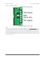
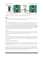
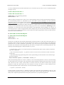
Serial Lines: RX, TX, and SIN
The qik can accept a logic-level (0 – 5 V), non-inverted serial input connected to its serial receive line, RX, and it
can handle baud rates from 1200 – 115,200 bps. This type of serial is often referred to as TTL and is an interface
method commonly used by microcontrollers. The voltage on this pin should not exceed 5 V. The qik provides
logic-level (0 – 5 V), non-inverted serial output on its serial transmit line, TX, in response to commands that
request information. Information requests always result in the transmission of a single byte per request. If you
aren’t interested in receiving feedback from the qik, you can leave this line disconnected.
The qik can also accept RS-232 serial input connected to the serial receive line, SIN. A computer serial port
typically communicates via RS-232 serial, which is inverted and uses voltages that would be out of spec for the
rest of the qik’s inputs (e.g. -12V to 12V), so SIN is the only pin to which it is safe to make a direct RS-232
connection. The qik does not have an RS-232 output, so you will need to use an RS-232 level converter connected
to the logic-level output if you want RS-232 feedback from the qik.
3. Connecting the Qik
Page 8 of 33
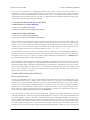
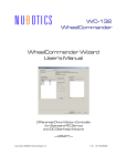
Qik 2s12v10 User's Guide
Qik 2s12v10 TTL serial connection example
(transmit and receive).
© 2001–2012 Pololu Corporation
Qik 2s12v10 RS-232 serial connection example
(qik receive only).
Both RX and SIN connect to the same serial port on the qik, so you should not use both of these inputs
simultaneously. Don’t forget to connect your serial source’s ground to the qik’s ground!
Reset
The reset line, RST, is an active-low input, which means that it resets the qik when driven low. This pin is
internally pulled to 5 V, so many applications can leave this pin disconnected.
Error
The error line, ERR, is an output that is connected to the red error LED and drives high (5 V) in response to an
error (which in turn lights the LED). Once an error occurs, the pin outputs high until a serial command is issued to
read the error byte, at which point the pin goes to a high-impedance state that is pulled low through the LED. This
allows you to connect the error lines of multiple qiks to the same digital input. Please note, however, that doing
this will cause the error LEDs of all connected qiks to turn on whenever one qik experiences an error; the ERR
output of the qik experiencing the error will drive the LEDs of any other qiks it is connected to, even though they
are not experiencing error conditions themselves. For more information on the possible error conditions, please
see Section 5.c. If you don’t care about error detection, you can leave this pin disconnected.
5V (out)
This line connects to the 5 V output of the qik’s voltage regulator and can be used to power additional electronics
in your system. It can safely supply up to 70 mA beyond what the board draws when VIN is 16 V. The closer the
input voltage is to 5 V, the more current the regulator can deliver without overheating.
VIN (out)
This is a convenient connection point to the input voltage that can be used as a power source for additional
electronics. Note that this pin is not intended to handle high currents, so it should not be used to power the qik
(use the large VIN and GND pads on the other side of the board for this). Do not attempt to draw more than 1 A
from this pin.
Connecting to a 3.3 V Microcontroller
The logic components on the qik 2s12v10 run at 5 V, but it is still possible to interface with a 3.3 V
microcontroller. The RX high input threshold is 3 V, so you can directly connect your microcontroller’s transmit
line to the qik’s TTL serial receive line (i.e. no additional components are required for sending commands to the
qik from a 3.3 V MCU).
If your microcontroller digital inputs are 5V-tolerant, you can make direct connections to the ERR and TX outputs
and RST input, which is weakly pulled to 5 V on the qik. If not, you can leave these optional outputs unconnected,
or you can use external components to decrease the voltage to a range your MCU can handle. A simple way to
accomplish this is by placing voltage dividers between each qik output and your MCU.
3. Connecting the Qik
Page 9 of 33
Qik 2s12v10 User's Guide
© 2001–2012 Pololu Corporation
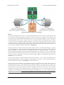
3.c. Included Hardware
The qik ships with a 12×1 straight 0.100" male header strip [http://www.pololu.com/catalog/product/965], a 3×2
straight 0.100" male header strip [http://www.pololu.com/catalog/product/966], three 2-pin terminal blocks
[http://www.pololu.com/catalog/product/2440], and three red shorting blocks [http://www.pololu.com/catalog/product/971].
For the most compact installation, you can solder wires directly to the qik pins themselves and skip using the
included hardware. For high-current installations, you should avoid using the supplied terminal blocks, which are
rated for up to 15 A, and instead directly solder the motor and power supply wires to the pads.
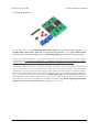
The included hardware allows you to make less permanent connections. You can break the 12×1 header strip
into a 6×1 piece and two 2×1 pieces and solder these strips into the qik’s logic pins where you plan on making
connections, or you can use a pair of pliers to pull out the two header pins in the original 12×1 strip for which the
qik has no holes and solder the entire strip to the qik’s logic pins. You can see this latter approach in the picture
below. You can then make your own cables that have female headers [http://www.pololu.com/catalog/category/50] on
them and plug these onto the male headers on your qik, or you can solder the pins to the other side of the board
and simply plug your qik into a breadboard. You might also consider using a 0.100" right-angle male header
strip [http://www.pololu.com/catalog/product/967] (not included) for a lower profile.
3. Connecting the Qik
Page 10 of 33
Qik 2s12v10 User's Guide
© 2001–2012 Pololu Corporation
The 3×2 header strip can be soldered to the jumper pins as shown above, which lets you make use of the included
shorting blocks, and the included terminal blocks lock together to make a single, 6-pin strip that you can solder to
the power side of the board.
3.d. Jumpers
The qik jumpers allow you to easily alter the behavior of the device. These jumpers can be left off for most
applications. If you use a jumper, it must be in place when the unit first starts up; changing the jumpers while
the unit is running does not take effect until the qik is reset or power is cycled. The only exception to this is the
removal of the demo mode jumper while the qik is in demo mode, which takes the qik out of demo mode.
Fixed-Baud Modes
The jumpers labeled BAUD1 and BAUD2 on the bottom of the qik (i.e. the two closest to the logic connection
side of the board) can be used to set the qik to fixed-baud mode when a shorting block is in place across one or
both jumper locations. When neither of these jumper locations has a shorting block, the qik is in auto-detect mode
and determines the baud rate automatically when it receives the first 0xAA (170 in decimal) byte. If you have a
noisy serial connection or find that the automatic baud detection is not working well for your application, you can
use a shorting block or some other jumper to ground pins BAUD1 and/or BAUD2 (the circular pads right next to
3. Connecting the Qik
Page 11 of 33
Qik 2s12v10 User's Guide
© 2001–2012 Pololu Corporation
the silkscreen labels). This sets the baud rate to a predetermined value, as described in the table below, and the qik
skips the automatic baud detection phase that normally occurs on start-up.
BAUD1 BAUD2
Baud Mode
Jumper Jumper
OFF
OFF
auto-detect baud rate (1200 – 115,200 bps)
ON
OFF
fixed baud rate at 115,200 bps
OFF
ON
fixed baud rate at 38,400 bps
ON
ON
fixed baud rate at 9,600 bps
Enable-CRC Mode
The jumper labeled CRC on the bottom of the qik enables cyclic redundancy check (CRC) mode when the
shorting block is in place. This allows you to increase the robustness of your qik connection through the addition
of a CRC error-checking byte to the end of the command packets you send to the qik. The default behavior of
the qik is to simply respond to a command packet once it receives the last byte. Grounding pin CRC (the circular
pad right next to the “CRC” silkscreen label) causes the qik to expect an additional CRC byte at the end of every
command packet. The CRC byte is the result of a CRC-7 computation on the entire command packet, as described
in Section 6. If this byte does not match the expected CRC, the qik ignores the command and uses the ERR pin
to announce a CRC error. When in this mode, the green heartbeat LED will flicker twice per heartbeat rather than
the single flash that occurs when CRC error checking is disabled.
Demo Mode
If you short pin BAUD1 to pin BAUD2 (the circular pads right next to the silkscreen labels) and reset the qik, it
enters demo mode and remains in demo mode for as long as the short is maintained. Demo mode gives you an easy
way to test your qik and troubleshoot your application for potential problems. In demo mode, the qik smoothly
ramps motor M0 from stopped to full-speed forward to full-speed reverse to stopped again over a few seconds. It
then does the same for motor M1. The red (error) LED is on while motor M0 is active and off while motor M1 is
active. The green (status) LED is on while the active motor is driving forward and off while the active motor is
driving in reverse. The motor indicator LEDs also light in response to the motor driver outputs.
Demo mode can help you determine before you’ve even written any code if you have an issue with your power
supply, such as insufficient ability to supply the current your motors are drawing or interference from motor noise.
While in demo mode, any serial data that is received by the qik on the RX line is echoed on the TX line, giving
you an easy way to test your serial connection. It accomplishes this by repeatedly checking the state of the serial
input pin and setting the state of the output pin to match. This process works reliably at low baud rates, but it is
not fast enough to keep up well at higher baud rates, which can result in an echoed byte that does not match the
one you transmitted.
3.e. Indicator LEDs and Phases of Operation
LED Overview
The qik has seven LEDs that are used to provide feedback about its state of operation:
• Power LED (blue): This blue LED is lit when the board is receiving power. It is located on the logic side
of the board.
• Status LED (green): This green LED provides a heartbeat to let you know that your qik is alive and what
state the qik is in, and it also acts as a serial activity indicator. It is located on the logic side of the board near
the jumpers.
3. Connecting the Qik
Page 12 of 33
Qik 2s12v10 User's Guide
© 2001–2012 Pololu Corporation
• Error LED (red): This red LED is tied to the ERR output pin and lights when the ERR pin drives high in
response to an error. Once an error occurs, the LED remains lit until a serial command is issued to read the
error byte, at which point the LED turns off. For more information on the possible error conditions, please
see Section 5.c. It is located on the logic side of the board.
• Motor Indicator LEDs: Each motor has a green and red indicator LED tied directly to the motor driver
outputs, for a total of four motor indicator LEDs. The color of the lit LED tells you the direction the motor
driver would turn an attached motor (green corresponds to “forward”), and the brightness of the LED gives
you feedback about the speed. Please note that it is normal for both of a motor’s red and green indicator
LEDs to appear lit simultaneously when a motor is attached and driven below full speed. This is because the
inductance of the motor keeps the current flowing during the coast phase of the PWM cycle, and since the
current cannot flow back through the driver, the only path it has is back through the LED that corresponds to
the opposite direction. These LEDs are located on the power side of the board.
Automatic Baud Detection Phase
When the qik first starts up in automatic baud detection mode, it enters a phase in which it is waiting to receive the
byte 0xAA (170 in decimal) at a baud rate that is within the range of 1200 bps to 115,200 bps. If the serial receive
line RX is pulled high, as is expected for an idle TTL serial line and the default state of an unconnected RX, the
green status LED fades in and out evenly every 0.8 s. If the serial receive line, RX, is held low (or, equivalently,
the SIN line is held high), this is indicative of a bad serial connection and the red error LED cycles between being
on for 0.4 s and off for 0.4 s (with the green status LED off).
If a serial byte other than 0xAA is received in this mode, or if 0xAA is transmitted at an invalid baud rate, the red
error LED turns on and stays on until the automatic baud detection phase ends. This gives you feedback that the
baud has not yet successfully been set and the controller is still in the automatic detection phase. Once the baud is
detected, this phase ends and the qik proceeds to normal operation.
Normal Operation
In normal operation, the green status LED very briefly flashes a heartbeat every 1.3 seconds. If the qik is in
enable-CRC mode, the heartbeat LED flickers twice in rapid succession; if not, it pulses just once per heartbeat. If
any serial activity is detected, the green status LED turns on until the next heartbeat turns it off. If an error occurs,
the red error LED turns on and remains on until you issue a get-error command (see Section 5.c).
Demo Mode
In demo mode, the status and error LEDs cycle through the pattern:
1. red (error) and green (status) ON
2. red (error) ON and green (status) OFF
3. red (error) OFF and green (status) ON
4. red (error) and green (status) OFF
This cycle takes five seconds, and each of the four LED states corresponds to a different output state of the qik’s
motor ports. When the red error LED is on, motor M0 is active, and when the red error LED is off, motor M1
is active. When the green status LED is on, the active motor is moving forward, and when the green status LED
is off, the active motor is moving in reverse. If you don’t have any motors connected, the motor indicator LEDs
light according to this pattern, and you can see them fade in and out as the motor speed ramps up and back down.
3. Connecting the Qik
Page 13 of 33
Qik 2s12v10 User's Guide
© 2001–2012 Pololu Corporation
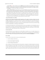
3.f. Board Dimensions and Mounting Information
The qik 2s12v10 measures 2.15" x 1.86" x 0.28" (54.6 x 47.2 x 7.1 mm) and weighs 0.5 oz (14 g) without the
header pins or terminal blocks installed. It has four mounting holes, one in each corner. The holes have a diameter
of 0.125" and are designed for #4 or M3 screws.
3. Connecting the Qik
Page 14 of 33
Qik 2s12v10 User's Guide
© 2001–2012 Pololu Corporation
4. Serial Interface
You can use the serial interface for three general purposes: querying the qik for information, setting its
configuration parameters, and sending it motor commands. Motor commands are strictly one-way; the qik
responds to all other commands by transmitting a single byte that either represents information that has been
requested or feedback on the effect of the issued command.
4.a. TTL and RS-232 Serial
The qik requires a logic-level (0 to 3.3-5 V, or “TTL”), non-inverted serial input connected to its serial receive
line, RX, or an RS-232 (inverted, ±3-15 V) serial input connected to its SIN pin. The serial interface is
asynchronous, meaning that the sender and receiver each independently time the serial bits; asynchronous serial
is available in computer serial ports (typically RS-232) and as hardware modules called “UARTs” on many
microcontrollers (typically TTL). Asynchronous serial output can also be “bit-banged” by a standard digital
output line under software control.
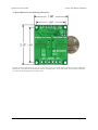
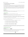
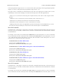
The data format is 8 data bits, one stop bit, with no parity, which is often expressed as 8-N-1. The diagram below
depicts a typical asynchronous, non-inverted TTL serial byte:
Diagram of a non-inverted TTL serial byte.
A non-inverted TTL serial line has a default (non-active) state of high. A transmitted byte begins with a single
low “start bit”, followed by the bits of the byte, least-significant bit (LSB) first. Logical ones are transmitted as
high (Vcc) and logical zeros are transmitted as low (0 V), which is why this format is referred to as “non-inverted”
serial. The byte is terminated by a “stop bit”, which is the line going high for at least one bit time. Because each
byte also requires start and stop bits, each byte takes 10 bit times to transmit, so the fastest possible data rate
in bytes per second is the baud rate divided by ten. At the maximum baud rate of 115,200 bits per second, the
maximum realizable data rate, with a start bit coming immediately after the preceding byte’s stop bit, is 11,520
bytes per second.
The voltage on the RX pin should not go below 0 V and should not exceed 5 V. The qik can accept a 3.3 V
serial input on this line, so you can send commands to the qik with a microcontroller running at 3.3 V. The qik
provides logic-level (0 – 5 V) serial output on its serial transmit line, TX, in response to commands that request
4. Serial Interface
Page 15 of 33
Qik 2s12v10 User's Guide
© 2001–2012 Pololu Corporation
information. Information requests result in the transmission of a single byte per request. If you aren’t interested in
receiving feedback from the qik, you can leave this line disconnected.
Note: Only the SIN line is compatible with RS-232 serial, which is inverted and uses voltages that
would be out of spec (e.g. -15 to 15 V). You should not connect RS-232 serial lines to RX or TX.
The qik does not provide RS-232 serial output.
4.b. Baud Rates
The qik 2s12v10 can handle baud rates between 1200 and 115,200 bps. In its default state, the qik starts up in an
automatic-baud-detection phase and waits to receive the byte 0xAA (decimal 170). The qik detects the baud rate
from this byte and proceeds to the normal operation phase at this baud rate. If you have the one or both of the
fixed-baud jumpers in place, the qik skips the autodetect phase and instead immediately begins normal operation
at a baud rate as indicated in the table below.
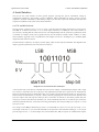
BAUD1 BAUD2
Baud Mode
Jumper Jumper
OFF
OFF
auto-detect baud rate (1200 – 115,200 bps)
ON
OFF
fixed baud rate at 115,200 bps
OFF
ON
fixed baud rate at 38,400 bps
ON
ON
fixed baud rate at 9,600 bps
Please see Section 3.d for more information on the fixed-baud jumpers.
4.c. Command Protocols
Once the qik has entered the normal operation phase, you can control it by issuing serial commands. If your qik
is set to automatically detect the baud, you must first send it the byte 0xAA (170 in decimal) in order to exit
autodetect mode and enter normal operation.
The qik serial command protocol is fairly simple. Communication is achieved by sending command packets
consisting of a single command byte followed by any data bytes that command requires. Command bytes always
have their most significant bits set (i.e. they range from 128 – 255, or 0x80 – 0xFF in hex) while data bytes always
have their most significant bits cleared (i.e. they range from 0 – 127, or 0x00 – 0x7F in hex). This means that each
data byte can only transmit seven bits of information.
One significant improvement over earlier Pololu serial controllers is the qik’s error handling, which allows the
user to specify responses to serial errors (including unknown commands, incorrectly formatted commands, and
hardware-level serial errors), motor fault errors, and motor over-current errors. The qik has a configuration
parameter that determines if the motors shut down when various errors occur, but the qik itself continues running
and accepting commands.
The qik responds to two sub-protocols:
Compact Protocol:
This is the simpler and more compact of the two protocols; it is the protocol you should use if your qik is the only
device connected to your serial line. The qik compact protocol command packet is simply:
command byte (with MSB set), any necessary data bytes
4. Serial Interface
Page 16 of 33
Qik 2s12v10 User's Guide
© 2001–2012 Pololu Corporation
For example, if we want to set motor M1 to full speed forward using the compact protocol, we could send the
following byte sequence:
in hex: 0x8D, 0x7F
in decimal: 141, 127
The byte 0x8D is a command for M1 forward, and the data byte contains the motor speed. Note that every qik
command byte starts with 0x8_ or 0x9_ when using the compact protocol.
Pololu Protocol:
This protocol is compatible with the serial protocol used by our other serial motor and servo controllers. As such,
you can daisy-chain a qik on a single serial line along with our other serial controllers (including additional qiks)
and, using this protocol, send commands specifically to the desired qik without confusing the other devices on the
line.
The Pololu protocol is to transmit 0xAA (170 in decimal) as the first (command) byte, followed by a devicenumber data byte. The default device number for the qik is 10, but this is a configuration parameter you can
change. Any qik on the line whose device number matches the specified device number accepts the command
that follows; all other Pololu devices ignore the command. The remaining bytes in the command packet are the
same as the compact protocol command packet you would send, with one key difference: the compact protocol
command byte is now a data byte for the command 0xAA and hence must have its most significant bit cleared.
Therefore, the command packet is:
0xAA, device # byte, command byte with MSB cleared, any necessary data bytes
For example, if we want to set motor M1 to full speed forward for a qik with device number 10, we could send
the following byte sequence:
in hex: 0xAA, 0x0A, 0x0D, 0x7F
in decimal: 170, 10, 13, 127
Note that 0x0D is the command 0x8D with its most significant bit cleared. Since all compact-protocol command
bytes start with 0x8n or 0x9n, these bytes all turn into data bytes 0x0n or 0x1n, respectively.
The qik responds to both the Pololu and Compact protocols on the fly; you do not need to use a jumper or
configuration parameter to identify which protocol you are using.
Procedure for Daisy-Chaining
Daisy-chaining multiple qiks together on the same serial line is simple. Individually assign each qik a different
device ID using the set configuration parameter command (see Section 5.d), and then connect your TTL serial
transmit line to each qik’s RX line or your RS-232 serial transmit line to each qik’s SIN line. If you wish, you
can connect all of the qiks’ ERR lines to a single input on your controlling module. When you issue your first
Pololu-protocol command, the qiks all automatically detect the baud from the initial 0xAA byte.
Connecting multiple serial outputs to one serial input is more complicated. Each device only transmits when
requested, so if each unit is addressed separately, multiple units will not transmit simultaneously. However, the
outputs are driven, so they cannot simply be wired together. Instead, you can use an AND gate (since the idle state
is high).
4. Serial Interface
Page 17 of 33
Qik 2s12v10 User's Guide
© 2001–2012 Pololu Corporation
If you want to daisy-chain a qik with other Pololu devices that use 0x80 as an initial command byte, the
procedure becomes slightly more complicated. You should first transmit the byte 0x80 so that these devices can
automatically detect the baud rate, and only then should you send the byte 0xAA so that the qik can detect the
baud rate. Once all devices have detected the baud rate, Pololu devices that expect a leading command byte of
0x80 should ignore command packets that start with 0xAA, and qiks will ignore command packets that start with
0x80.
4. Serial Interface
Page 18 of 33
Qik 2s12v10 User's Guide
© 2001–2012 Pololu Corporation
5. Serial Parameters and Commands
5.a. Configuration Parameters
The qik 2s12v10 has twelve configuration parameters that are saved in non-volatile memory, which means that
once set, these parameters will retain their values even if the unit is powered off. Commands 0x83 and 0x84 are
used to read and write these parameter values, respectively (see Section 5.d). Please note that the memory used to
store these parameters is only rated for approximately 100,000 erase/write cycles, so you should avoid putting setparameter commands within loops that are executed many times a second; it is intended that these parameters will
initially be configured as desired and then only changed occasionally. The parameters are numbered as follows:
0: Device ID
default value: 10
allowed values: 0 – 127
This parameter determines which device ID the unit responds to when the Pololu protocol is used. You should
only have one qik on your serial line at a time when setting this parameter.
1: PWM Parameter
default value: 0 (high-frequency, 7-bit mode—PWM frequency of 19.7 kHz)
allowed values: 0 – 5
This parameter determines resolution and frequency of the pulse width modulation (PWM) signal used to control
motor speed. Note that setting this parameter while the motors are running causes them to stop.
The least-significant bit (bit 0) selects for 7-bit resolution when cleared (i.e. a speed of 127 results in full voltage
to the motors) and 8-bit resolution when set (i.e. a speed of 255 results in full voltage to the motors). A PWM with
7-bit resolution has twice the frequency of one with 8-bit resolution.
Bits 1 and 2 give you additional control over the PWM frequency. When combined with the resolution bit, PWM
parameter can be set to the following six values:
• 0 = 7-bit resolution, high-frequency (PWM frequency of 19.7 kHz, which is ultrasonic)
• 1 = 8-bit resolution, high-frequency (PWM frequency of 9.8 kHz)
• 2 = 7-bit resolution, medium-frequency (PWM frequency of 2.5 kHz)
• 3 = 8-bit resolution, medium-frequency (PWM frequency of 1.2 kHz)
• 4 = 7-bit resolution, low-frequency (PWM frequency of 310 Hz)
• 5 = 8-bit resolution, low-frequency (PWM frequency of 150 Hz)
Using a PWM parameter of zero produces the highest PWM frequency of approximately 20 kHz, which is outside
the range of human hearing and can help make your motors quieter. Using lower frequencies has the benefit of
decreasing power losses due to switching.
2: Shut Down Motors on Error
default value: 1 (stop motors on any serial error)
allowed values: 0 – 7
This parameter controls whether motors M0 and M1 are stopped in response to the various error conditions that
can occur. The three least-significant bits of the parameter let you specify whether the motors are stopped if a
serial error occurs, a motor-over-current error occurs, or a motor-fault error occurs:
• bit 0: if this bit is set, stop motors M0 and M1 when any serial error occurs.
5. Serial Parameters and Commands
Page 19 of 33
Qik 2s12v10 User's Guide
© 2001–2012 Pololu Corporation
• bit 1: if this bit is set, stop motors M0 and M1 when any motor-over-current error occurs.
• bit 2: if this bit is set, stop motors M0 and M1 when any motor-fault error occurs.
When this parameter has a value of 7, both motors M0 and M1 are stopped as a safety precaution whenever
any error occurs; conversely, if this parameter has a value of 0, no error causes the motors to stop. For more
information on the various types of errors that can occur, see Section 5.c.
3: Serial Timeout
default value: 0 (serial timeout disabled)
allowed values: 0 – 127
When this parameter has a value of zero, the serial timeout feature is inactive. Otherwise, the value of this
parameter controls how much time can elapse between receptions of valid command packets before a serial
timeout error is generated. This can be used as a general safety feature to allow the qik to identify when
communication with the controlling device is lost and shut down the motors as a result. Note: The shut-downmotors-on-error parameter must have bit 0—its serial error shut down bit—set for the timeout error to turn off the
motors.
The timeout duration is specified in increments of 250 ms (a quarter of a second) and is calculated as the four
least-significant bits (which are interpreted as a number from 0 – 15) times the quantity 2 to the three mostsignificant bits (which are interpreted as a number from 0 – 7) power. If the four least-significant bits are called L
and the three most-significant bits are called M, the equation for the length of the timeout duration would be:
• timeout = 0.25 seconds * L * 2M = L * 2M-2 seconds
For example, if the timeout parameter is set as 0x5E (01011110 in binary), we have that L = 1110 (binary) = 14
(decimal) and M = 101 (binary) = 5 (decimal), which results in a timeout duration of:
• 0.25s * 14 * 25 = 112 seconds.
The maximum timeout duration (arising from a parameter value of 127) is 8 minutes and the minimum timeout
duration (arising from a parameter value of 1) is 250 ms.
4: Motor M0 Acceleration
5: Motor M1 Acceleration
default value: 0 (controlled speed ramping disabled)
allowed values: 0 – 127
When one of these parameters has a value of zero, acceleration control of the associated motor is inactive.
Otherwise, the M0 and M1 acceleration parameters control the rate at which the the M0 and M1 speeds are
allowed to increase over time, respectively. These parameters provide a great way to smooth out your motor
control and reduce current spikes caused by sharp increases in motor speed or changes in motor direction.
When acceleration control is active, a set-motor command tells the qik your desired target direction and speed.
One of three cases can then occur:
• If the target speed is lower than the motor speed and the target direction matches the current direction, the
motor speed is immediately set to the target speed.
• If the target speed is higher than the motor speed and the target direction matches the current direction, the
qik linearly ramps the motor speed up to the target speed by adding the value of the associated acceleration
parameter to the speed every 40 ms.
5. Serial Parameters and Commands
Page 20 of 33
Qik 2s12v10 User's Guide
© 2001–2012 Pololu Corporation
• If the target direction does not match the current direction, the motor speed is immediately set to zero, and
the qik then proceeds to ramp the motor speed linearly from zero to the target speed by adding the value of
the associated acceleration parameter to the speed every 40 ms.
For example, if the M0 acceleration parameter is 1, it takes a stationary motor M0 5.08 s (127 * 40 ms) to reach
a speed of 127. If the M0 acceleration parameter is 127, it takes a stationary motor M0 40 ms to reach a speed of
127. The qik actually updates the motor speed 100 times per second, so the speed is really being incremented by
a quarter of the acceleration parameter every 10 ms, which results in even smoother acceleration.
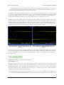
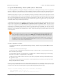
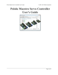
The following oscilloscope captures show qik acceleration in action. When the yellow line is low, the motor driver
is in coast mode, and when the yellow line is high, the motor driver is driving with one output at VIN and the
other at ground. The left capture shows the effect of using an acceleration of 127, and the right capture shows a
more gradual acceleration using a parameter value of 28. The captures were taken with a low PWM frequency
(310 Hz) to make it easier to see the effect of the acceleration on the motor driver output.
Qik 2s12v10 motor driving from speed 0 to 127
with acceleration of 127 and PWM frequency of
310 Hz.
Qik 2s12v10 motor driving from speed 0 to 127
with acceleration of 28 and PWM frequency of
310 Hz.
Please note that acceleration does not apply to braking or to a speed decrease that does not also result in a change
of direction. Motor speed can also be influenced by current-limit settings, which impose additional constraints on
the logic detailed above. Please see the current-limit parameters, which are documented later in this section, for
more information.
6: Motor M0 Brake Duration
7: Motor M1 Brake Duration
default value: 0 (braking on direction change disabled)
allowed values: 0 – 127
When one of these parameters has a value of zero, requested changes of direction for the associated motor occur
immediately. Otherwise, the M0 and M1 brake duration parameters control the amount of time motors M0 and
M1 spend braking before the motor direction is changed from forward to reverse or vice versa. Along with the
acceleration parameters, these parameters provide a great way to smooth out your motor control and reduce
current spikes caused by changes in motor direction.
These parameters represent a time duration in units of 10 ms, so a value of 127 results in a brake duration of
1.27 s. For example, if the M0 brake duration has a value of 50 and M0 is moving forward, issuing an M0-reverse
5. Serial Parameters and Commands
Page 21 of 33
Qik 2s12v10 User's Guide
© 2001–2012 Pololu Corporation
set-motor command sets motor M0 to full brake for 0.5 s before the qik acts on the set-motor command and starts
moving in reverse.
8: Motor M0 Current Limit / 2
9: Motor M1 Current Limit / 2
default value: 0 (current-limiting disabled)
allowed values: 0 – 127
When one of these parameters has a value of zero, current limiting is inactive for the associated motor. Otherwise,
the current-limiting behavior is determined by the current-limit response parameters (see their parameter
description below for more details). Please note that these parameters specify one half of the desired current
limit for each motor. For example, if you want the current limit to be 16 (which corresponds to approximately
2.4 A), you should set this parameter to 8. The current limit is compared to the an 8-bit representation of the motor
current; you can request these motor currents by issuing a get-motor-current command (see Section 5.g for more
information). To convert this 8-bit current representation to an approximate current, multiply it by 150 mA. To
convert this parameter value to an approximate current, multiply it by 300 mA (since this parameter is multiplied
by two before being compared to the motor current). Please note that the approximate current can differ from the
actual current by as much as 20%.
10: Motor M0 Current-Limit Response
11: Motor M1 Current-Limit Response
default value: 4
allowed values: 0 – 127
The qik lets you limit the current motors M0 and M1 are allowed to draw. It does this by decreasing power to
the motors if their currents exceed the current limits that have been set (see the description of the current-limit
parameters above for more information). Specifically, every time the motor speed is updated, which happens
100 times per second, the current being drawn by the motors is compared to the current-limit parameters. The
following current-limiting logic is then performed every 10 ms:
• If current limit = 0, there is no current limit; take no actions based on motor current, and use acceleration
logic only, if applicable.
• Else if current-limit response = 0, generate a motor-over-current error if the motor current exceeds the
current limit.
• Else add the following signed change to the motor speed, making sure the result does not exceed the target
speed or go negative:
min( acceleration, response * ( current limit – current ) ) / 4
If the current-limiting feature for a motor is enabled (i.e. the current limit parameter is not zero), current limiting
can affect that motor’s acceleration. The current-limit response parameters determine how the motors react when
their currents are in the vicinity of their limits. If a motor’s current is just under the limit and its response
parameter is small, the motor speed may not be allowed to increase as much as would be dictated by the
acceleration parameter alone. If the current is over the current limit, the quantity:
• response * ( current limit – current )
becomes negative, and the effect is a reduction in motor speed. The motor speed continues to drop at a rate
proportional to the difference between the current and the limit until the current equals the limit. You will most
likely need to empirically determine the best response parameter for your particular application.
5. Serial Parameters and Commands
Page 22 of 33
Qik 2s12v10 User's Guide
© 2001–2012 Pololu Corporation
5.b. 0x81: Get Firmware Version
Command 0x81 (129): Get Firmware Version
Compact protocol: 0x81
Pololu protocol: 0xAA, device ID, 0x01
This command returns the a single ASCII byte that represents the version of the firmware running on the qik. All
qik 2s12v10’s produced so far have firmware version ‘1’ or ‘2’.
Firmware version 2 fixes a bug in the handling of motor fault errors (see Section 5.c for more information on
motor fault errors). Hardware-level motor errors cause the motor driver ICs on the qik to latch their outputs off
until the appropriate inputs are toggled. Firmware version 1 does not correctly toggle these inputs, so qiks with
firmware version 1 must have their power cycled in order to re-enable a motor driver that has experienced the
error. Firmware version 2 performs the necessary toggling automatically whenever a motor fault error occurs.
5.c. 0x82: Get Error Byte
Command 0x82 (130): Get Error Byte
Compact protocol: 0x82
Pololu protocol: 0xAA, device ID, 0x02
The qik maintains an error byte, the bits of which, when set, reflect various errors that have occurred since the byte
was last read using this command. If we call the least-significant bit 0, the bits of the error byte are as follows:
• bit 0: Motor 0 Fault
A hardware-level error signaled by motor M0’s driver to indicate overtemperature or a short-circuit condition
on the output.
• bit 1: Motor 1 Fault
A hardware-level error signaled by motor M1’s driver to indicate overtemperature or a short-circuit condition
on the output.
• bit 2: Motor 0 Over Current
This error bit is set when the motor M0 current exceeds the motor M0 current limit parameter, current
limiting is enabled (i.e. the current limit is not zero), and the current limit response parameter is set to zero.
If the current limit response parameter is not zero, the qik automatically decreases the average motor voltage
to keep the current at the limit, and this error bit is not set.
• bit 3: Motor 1 Over Current
This error bit is set when the motor M1 current exceeds the motor 1 current limit parameter, current limiting
is enabled (i.e. the current limit is not zero), and the current limit response parameter is set to zero. If the
current limit response parameter is not zero, the qik automatically decreases the average motor voltage to
keep the current at the limit, and this error bit is not set.
• bit 4: Serial Hardware Error
A hardware-level error that occurs when a byte’s stop bit is not detected at the expected place or when the
hardware serial receive buffer is full. The former condition can occur if you are communicating at a baud
rate that differs from the qik’s baud rate. The latter condition should not occur during normal operation.
• bit 5: CRC Error
This error occurs when the qik is running in CRC-enabled mode (i.e. the CRC-enable jumper is in place) and
the cyclic redundancy check (CRC) byte at the end of the command packet does not match what the qik has
5. Serial Parameters and Commands
Page 23 of 33
Qik 2s12v10 User's Guide
© 2001–2012 Pololu Corporation
computed as that packet’s CRC. In such a case, the qik ignores the command packet and generates a CRC
error. See Section 6 for more information on cyclic redundancy checking.
• bit 6: Format Error
This error occurs when the qik receives an incorrectly formatted or nonsensical command packet. For
example, if the command byte does not match a known command, data bytes are outside of the allowed range
for their particular command, or an unfinished command packet is interrupted by another command packet,
this bit is set.
• bit 7: Timeout
It is possible to use a configuration parameter to enable the qik’s serial timeout feature (see Section 5.a).
When enabled, the qik sets this bit if the timeout period set by the configuration parameter has elapsed. The
timeout timer is reset every time a command packet is received. A timeout error can be used to shutdown the
motors in the event that serial communication between the qik and its controller is disrupted.
In response to an error, the qik lights the red status LED and drives the ERR pin high until this command is called.
Calling this command clears the error byte, turns the red status LED off, and sets the ERR pin to high-impedance
(the error LED pulls it low). The shut-down-on-error configuration parameter can be used to stop motors M0 and
M1 as a safety precaution when a serial error occurs, a motor-fault error occurs, or a motor-over-current error
occurs. See Section 5.a for more information on this configuration parameter.
5.d. 0x83 & 0x84: Get & Set Configuration Parameter
Command 0x83 (131): Get Configuration Parameter
Compact protocol: 0x83, parameter number
Pololu protocol: 0xAA, device ID, 0x03, parameter number
This command lets you request the current value of any of the twelve configuration parameters detailed in Section
5.a. This command prompts the qik to transmit a single byte that represents the requested parameter value. If you
request an invalid parameter (i.e. if parameter number ≥ 12), the value transmitted by the qik (typically 0xFF) has
no meaning and a format error is generated.
Command 0x84 (132): Set Configuration Parameter
Compact protocol: 0x84, parameter number, parameter value, 0x55, 0x2A
Pololu protocol: 0xAA, device ID, 0x04, parameter number, parameter value, 0x55, 0x2A
This command lets you set the value of any of the twelve configuration parameters detailed in Section 5.a. The
final two bytes of the command packet—0x55 (85) and 0x2A (42)—are format bytes that make it more difficult
for this command to be accidentally sent, as might result from a noisy serial connection or buggy user code. If
either of the format bytes differs from the expected value, the command is ignored and a format error is generated.
It takes the qik approximately 4 ms to finish processing this command, at which point the qik transmits a single
return byte that contains information about whether the process was successful. You should not send commands
to the qik until you have received this return byte, or until at least 4 ms have elapsed. The return byte can have the
following values:
• 0: Command OK (success)
• 1: Bad Parameter (failure due to invalid parameter number)
• 2: Bad value (failure due to invalid parameter value for the specified parameter number)
Failure results in a format error.
5. Serial Parameters and Commands
Page 24 of 33
Qik 2s12v10 User's Guide
© 2001–2012 Pololu Corporation
Once you have set the value of a configuration parameter, that value is saved in non-volatile memory, so it
will persist even if the qik is subsequently turned off or reset. Please note that the memory used to store these
parameters is only rated for approximately 100,000 erase/write cycles, so you should avoid putting this command
within loops that are executed many times a second; it is intended that the configuration parameters will initially
be set as desired and then only changed occasionally.
5.e. 0x86 & 0x87: Motor M0 & M1 Variable Brake
Command 0x86 (134): Motor M0 Brake
Compact protocol: 0x86, brake amount
Pololu protocol: 0xAA, device ID, 0x06, brake amount
Command 0x87: Motor M1 Brake
Compact protocol: 0x87 (135), brake amount
Pololu protocol: 0xAA, device ID, 0x07, brake amount
These commands will set the specified motor to variable brake based on the brake amount data byte. When brake
amount is zero, the motor outputs are high impedance, which lets the motor turn freely (coast). When brake
amount is 127, the motor outputs are both tied to ground, which causes the motor to brake. For values of brake
amount between 0 and 127, the motor outputs will PWM between high impedance (coast) and ground (brake),
with the percentage of the time the motor spends braking given by (brake amount / 127) * 100%.
Please note that a brake amount value of 127 always results in full braking, even when the PWM configuration
parameter selects for 8-bit resolution. Braking is not affected by the acceleration parameters, and transitioning
from brake to drive or vice versa does not produce a change-of-direction “brake duration” (see Section 5.a for
more information about these configuration parameters).
You can familiarize yourself with motor coasting and braking using nothing more than a motor. First, with your
motor disconnected from anything, try rotating the output shaft and note how easily it turns. Then hold the two
motor leads together and try rotating the output shaft again. You should notice significantly more resistance while
the leads are shorted together. A brake amount of zero is equivalent to disconnecting your motor and letting it turn
freely; a brake amount of 127 is equivalent to shorting the motor leads together. All other brake amount values
produce a mixture of the two scenarios.
5.f. 0x88 - 0x8F: Set Motor Forward/Reverse
Motor Control Overview
The qik can independently drive up to two bidirectional brushed DC motors, referred to as M0 and M1, using
two VNH2SP30 motor drivers. Variable speed is achieved with 7-bit or 8-bit pulse width modulated (PWM)
outputs at one of several selectable frequencies. 7-bit control allows for PWM frequencies of 19.7 kHz, 2.5 kHz,
and 310 Hz; 8-bit control allows for PWM frequencies of 9.8 kHz, 1.2 kHz, and 150 Hz. The highest achievable
frequency of 19.7 kHz is ultrasonic, which can result in quieter motor control. Lower frequencies might produce
louder motor noise, but they can help decrease power losses due to switching. The resolution and frequency can
be set via the qik’s PWM configuration parameter (see Section 5.a).
The motor direction convention used in this document is that “forward” corresponds to holding the + output at
VIN while PWMing the - output between ground and high impedance. “Reverse” is the same as forward but with
the outputs flipped: - is held at VIN while + is PWMed between ground and high impedance. As a result, the
motor is rapidly alternating between drive and coast when the direction is “forward” or “reverse”. Variable speed
control is achieved by varying the fraction of the cycle that the motor outputs are driving. Full speed arises when
the motor outputs are driving 100% of the time (one motor output is held at steady at VIN and the other steady
at ground). In 7-bit mode, motor speed ranges from stopped (high-impedance outputs, or “coast”) to full speed
5. Serial Parameters and Commands
Page 25 of 33
Qik 2s12v10 User's Guide
© 2001–2012 Pololu Corporation
as the speed parameter ranges from 0 to 127. In 8-bit mode, motor speed ranges from stopped (high-impedance
outputs, or “coast”) to full speed as the speed parameter ranges from 0 – 255.
The eight set-motor commands are enumerated below, but some users might prefer to think of the set-motor
command byte in terms of the meanings of various bits in the byte (bit 0 is the least-significant bit):
• bit 7 (sync bit): Set this bit when using the Compact Protocol; clear this bit when using the Pololu
Protocol.
• bits 6:3 (set motor command bits): for this command, set bit 3 and clear bits 4 – 6.
• bit 2 (motor bit): Set this bit for motor M1; clear this bit for motor M0.
• bit 1 (direction bit): Set this bit for “reverse”; clear this bit for “forward”.
• bit 0 (speed mode bit): This is the eighth motor speed bit when the qik is in 8-bit PWM mode (i.e. set this
bit to add 128 to the speed data byte). This bit has no effect when the qik is in 7-bit PWM mode.
Motor M0 Commands
Commands 0x88 – 0x8B apply to motor M0. In 8-bit mode, commands 0x89 and 0x8B set the motor speed to
128+motor speed; in 7-bit mode, command 0x89 is identical to command 0x88 and command 0x8B is identical
to command 0x8A.
For example, in 8-bit mode, the command packet 0x88, 0x7F sets motor M0 speed to 127 out of a maximum
of 255, which turns the motor at half speed. The command packet 0x89, 0x7F sets motor M0 speed to 127+128
= 255, which turns the motor at full speed. In 7-bit mode, both commands set motor M0 speed to 127 out of a
maximum of 127, which turns the motor at full speed.
Command 0x88 (136): Motor M0 Forward
Compact protocol: 0x88, motor speed
Pololu protocol: 0xAA, device ID, 0x08, motor speed
Command 0x89 (137): Motor M0 Forward (speed + 128; used in 8-bit mode)
Compact protocol: 0x89, motor speed
Pololu protocol: 0xAA, device ID, 0x09, motor speed
Command 0x8A (138): Motor M0 Reverse
Compact protocol: 0x8A, motor speed
Pololu protocol: 0xAA, device ID, 0x0A, motor speed
Command 0x8B (139): Motor M0 Reverse (speed + 128; used in 8-bit mode)
Compact protocol: 0x8B, motor speed
Pololu protocol: 0xAA, device ID, 0x0B, motor speed
Motor M1 Commands
Commands 0x8C – 0x8F apply to motor M1. In 8-bit mode, commands 0x8D and 0x8F set the motor speed to
128+motor speed; in 7-bit mode, command 0x8D is identical to command 0x8C and command 0x8F is identical
to command 0x8E.
For example, in 8-bit mode, the command packet 0x8C, 0x7F sets motor M1 speed to 127 out of a maximum
of 255, which turns the motor at half speed. The command packet 0x8D, 0x7F sets motor M1 speed to 127+128
5. Serial Parameters and Commands
Page 26 of 33
Qik 2s12v10 User's Guide
© 2001–2012 Pololu Corporation
= 255, which turns the motor at full speed. In 7-bit mode, both commands set motor M1 speed to 127 out of a
maximum of 127, which turns the motor at full speed.
Command 0x8C (140): Motor M1 Forward
Compact protocol: 0x8C, motor speed
Pololu protocol: 0xAA, device ID, 0x0C, motor speed
Command 0x8D (141): Motor M1 Forward (speed + 128; used in 8-bit mode)
Compact protocol: 0x8D, motor speed
Pololu protocol: 0xAA, device ID, 0x0D, motor speed
Command 0x8E (142): Motor M1 Reverse
Compact protocol: 0x8E, motor speed
Pololu protocol: 0xAA, device ID, 0x0E, motor speed
Command 0x8F (143): Motor M1 Reverse (speed + 128; used in 8-bit mode)
Compact protocol: 0x8F, motor speed
Pololu protocol: 0xAA, device ID, 0x0F, motor speed
5.g. 0x90 & 0x91: Get Motor M0 & M1 Current
Command 0x90 (144): Get Motor M0 Current
Compact protocol: 0x90
Pololu protocol: 0xAA, device ID, 0x10
Command 0x91 (145): Get Motor M1 Current
Compact protocol: 0x91
Pololu protocol: 0xAA, device ID, 0x11
These commands return 8-bit representations of the average motor currents over the last 5 ms. To convert the
returned value to an approximate current, multiply it by 150 mA. Please note that the actual current could differ
from this value by as much as 20%, so you might consider empirically characterizing the current feedback from
each motor driver to obtain a more accurate relationship between the values returned by this command and the
actual driver output current.
5.h. 0x92 & 0x93: Get Motor M0 & M1 Speed
Command 0x92 (146): Get Motor M0 Speed
Compact protocol: 0x92
Pololu protocol: 0xAA, device ID, 0x12
Command 0x93 (147): Get Motor M1 Speed
Compact protocol: 0x93
Pololu protocol: 0xAA, device ID, 0x13
These commands return the present motor speeds, which can be useful in determining the current state of an
accelerating motor or the speed that results from active current limiting. Please note that this command returns the
speeds to which the qik is trying to set the motors, not necessarily their actual speeds. For example, if the qik is
trying to drive a stalled motor at full speed, the returned speed might be 255 (0xFF) even though the actual motor
5. Serial Parameters and Commands
Page 27 of 33
Qik 2s12v10 User's Guide
© 2001–2012 Pololu Corporation
speed is zero. To get a measure of actual motor speed, you would need to obtain external feedback, such as from
an encoder.
The values returned by these commands range from 0 to 127 in 7-bit mode and from 0 to 255 in 8-bit mode. The
returned motor speed is zero if the associated motor is braking.
5. Serial Parameters and Commands
Page 28 of 33
Qik 2s12v10 User's Guide
© 2001–2012 Pololu Corporation
6. Cyclic Redundancy Check (CRC) Error Detection
For certain applications, verifying the integrity of the data you’re sending and receiving can be very important.
Because of this, the qik has optional 7-bit cyclic redundancy checking, which is similar to a checksum but more
robust as it can detect errors that would not affect a checksum, such as an extra zero byte or bytes out of order.
When the CRC jumper is in place, cyclic redundancy checking is enabled. In CRC mode, the qik expects an extra
byte to be added onto the end of every command packet. The most-significant bit of this byte must be cleared, and
the seven least-significant bits must be the 7-bit CRC for that packet. If this CRC byte is incorrect, the qik will
set its CRC error bit in the error byte and ignore the command. The qik does not append a CRC byte to the data it
sends back, which always consists of just one byte.
A detailed account of how cyclic redundancy checking works is beyond the scope of this document, but you can
find a wealth of information using Wikipedia [http://en.wikipedia.org/wiki/Cyclic_redundancy_check]. The quick version
is that a CRC computation is basically a carryless long division of a CRC “polynomial”, 0x91, into your message
(expressed as a continuous stream of bits), where all you care about is the remainder. The qik uses CRC-7,
which means it uses an 8-bit polynomial (whose most-significant bit, or MSB, must always be 1) and, as a result,
produces a 7-bit remainder. This remainder is the lower 7 bits of the CRC byte you tack onto the end of your
command packets.
The CRC implemented on the qik is the same as on the jrk [http://www.pololu.com/catalog/product/1392]
motor controller but differs from that on the TReX [http://www.pololu.com/catalog/product/777] motor
controller. Instead of being done MSB first, it is LSB first, to match the order in which the bits
are transmitted over the serial line. In standard binary notation, the number 0x91 is written as
10010001. However, the bits are transmitted in this order: 1, 0, 0, 0, 1, 0, 0, 1, so we will write it
as 10001001 to carry out the computation below.
The CRC-7 algorithm is as follows:
1. Express your 8-bit CRC-7 polynomial and message in binary, LSB first. The polynomial 0x91 is written
as 10001001.
2. Add 7 zeros to the end of your message.
3. Write your CRC-7 polynomial underneath the message so that the LSB of your polynomial is directly
below the LSB of your message.
4. If the LSB of your CRC-7 is aligned under a 1, XOR the CRC-7 with the message to get a new message;
if the LSB of your CRC-7 is aligned under a 0, do nothing.
5. Shift your CRC-7 right one bit. If all 8 bits of your CRC-7 polynomial still line up underneath message
bits, go back to step 4.
6. What’s left of your message is now your CRC-7 result (transmit these seven bits as your CRC byte when
talking to the qik with CRC enabled).
If you’ve never encountered CRCs before, this probably sounds a lot more complicated than it really is. The
following example shows that the CRC-7 calculation is not that difficult. For the example, we will use a two-byte
sequence: 0x83, 0x01 (the command packet to get the PWM configuration parameter byte).
Steps 1 & 2 (write as binary, add 7 zeros to the end of the message):
CRC-7 Polynomial = [1 0 0 0 1 0 0 1]
message = [1 1 0 0 0 0 0 1] [1 0 0 0 0 0 0 0] 0 0 0 0 0 0 0
6. Cyclic Redundancy Check (CRC) Error Detection
Page 29 of 33
Qik 2s12v10 User's Guide
© 2001–2012 Pololu Corporation
Steps 3, 4, & 5:
_______________________________________________
1 0 0 0 1 0 0 1 ) 1 1 0 0 0 0 0 1 1 0 0 0 0 0 0 0 0 0 0 0 0 0 0
XOR 1 0 0 0 1 0 0 1 | | | | | | | | | | | | | | |
--------------- | | | | | | | | | | | | | | |
1 0 0 1 0 0 0 1 | | | | | | | | | | | | | |
shift ----> 1 0 0 0 1 0 0 1 | | | | | | | | | | | | | |
_______________ | | | | | | | | | | | | | |
1 1 0 0 0 0 0 0 | | | | | | | | | | |
1 0 0 0 1 0 0 1 | | | | | | | | | | |
_______________ | | | | | | | | | | |
1 0 0 1 0 0 1 0 | | | | | | | | | |
1 0 0 0 1 0 0 1 | | | | | | | | | |
_______________ | | | | | | | | | |
1 1 0 1 1 0 0 0 | | | | | | |
1 0 0 0 1 0 0 1 | | | | | | |
_______________ | | | | | | |
1 0 1 0 0 0 1 0 | | | | | |
1 0 0 0 1 0 0 1 | | | | | |
_______________ | | | | | |
1 0 1 0 1 1 0 0 | | | |
1 0 0 0 1 0 0 1 | | | |
_______________ | | | |
1 0 0 1 0 1 0 0 | |
1 0 0 0 1 0 0 1 | |
_______________ | |
1 1 1 0 1 0 0 = 0x17
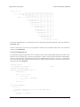
So the full command packet we would send to retrieve the PWM configuration parameter with CRC enabled is:
0x83, 0x01, 0x17
There are some tricks you can use in your programs to make the CRC calculation much faster. You can find an
example of this Section 6.a.
6.a. CRC Computation in C
The following example program shows how to compute a CRC in the C programming language. The idea is that
the CRC of every possible byte is stored in a lookup table, so that it can be quickly loaded when computing the
CRC of a longer message. The individual CRC bytes are XORed together with the C operator ^ to get the final
CRC of the message. In the example main() routine, this is applied to generate the CRC byte in the message 0x83,
0x01, that was used in Section 6.
#include <stdio.h>
const unsigned char CRC7_POLY
unsigned char CRCTable[256];
= 0x91;
unsigned char GetCRC(unsigned char val)
{
unsigned char j;
for (j = 0; j < 8; j++)
{
if (val & 1)
val ^= CRC7_POLY;
val >>= 1;
}
}
return val;
void GenerateCRCTable()
{
int i, j;
// generate a table value for all 256 possible byte values
for (i = 0; i < 256; i++)
{
CRCTable[i] = GetCRC(i);
6. Cyclic Redundancy Check (CRC) Error Detection
Page 30 of 33
Qik 2s12v10 User's Guide
}
© 2001–2012 Pololu Corporation
}
unsigned char CRC(unsigned char message[], unsigned char length)
{
unsigned char i, crc = 0;
}
for (i = 0; i < length; i++)
crc = CRCTable[crc ^ message[i]];
return crc;
int main()
{
unsigned char message[3] = {0x83, 0x01, 0x00};
int i, j;
GenerateCRCTable();
message[2] = CRC(message, 2);
}
for (i = 0; i < sizeof(message); i++)
{
for (j = 0; j < 8; j++)
printf("%d", (message[i] >> j) % 2);
printf(" ");
}
printf("\n");
return 0;
6. Cyclic Redundancy Check (CRC) Error Detection
Page 31 of 33
Qik 2s12v10 User's Guide
© 2001–2012 Pololu Corporation
7. Troubleshooting
The following are some suggestions for ways you can troubleshoot your qik:
• Test for life: With nothing more than power connected, look for a green LED heartbeat. If you do not see
the green LED flashing, you either lack sufficient power (e.g. the voltage is out of range or the power supply
is too noisy) or your qik is damaged. See Section 3.a for more information about power requirements.
• Test your serial connection: Put on the BAUD1 jumper (with the BAUD2 and CRC jumpers off),
connect your TTL serial control source to the qik’s RX pin or RS-232 serial control source to the qik’s SIN
pin, reset the board, and send 0xBF (191) at 115.2 kbps. You should see the red error LED turn on. If you
then send the command 0x82 (130) at 115.2 kbps, you should see the green LED pulse on (this might be
hard to distinguish from the heartbeat LED), the red LED turn off, and, if you have a connection to the qik’s
serial output, you should receive the byte 0x40 (64). You should try this first with a computer running our
Serial Transmitter Utility [http://www.pololu.com/docs/0J23], which will help you determine if the problem is
with your code.
• Test your motors: Try running the qik in demo mode first without motors connected and then with
motors connected (see Section 3.d for more information about demo mode). If the qik experiences problems
only with motors connected, this is a sign that your problems are likely due to insufficient motor power or
motor-induced noise. Ensure that your motor power supply can provide the current your motors are drawing,
and ensure that your motors are not trying to draw more current than the qik can supply (13 A continuous per
motor channel, 30 A peak). Take steps to limit motor noise (e.g. solder 0.1 uF capacitors across your motor
terminals and use short, twisted motor leads).
If your problems persist, please post on our support forum
[http://www.pololu.com/contact] directly.
7. Troubleshooting
[http://forum.pololu.com/]
or contact us
Page 32 of 33
Qik 2s12v10 User's Guide
© 2001–2012 Pololu Corporation
8. Arduino Library
We have written a basic Arduino library for the qik dual serial motor controllers that makes it simple to
interface the qik 2s12v10 with an Arduino [http://www.pololu.com/catalog/product/2191]. The library handles the details
of serial communication with the qik, and two example programs are included to help you configure the qik and
get started controlling two brushed DC motors. Please refer to the documentation for the library on GitHub for
more details.
8. Arduino Library
Page 33 of 33