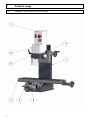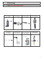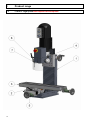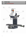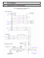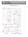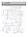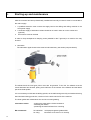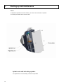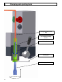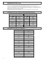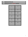
1
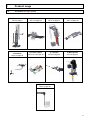
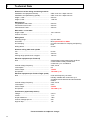
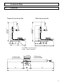
Operating Instructions Universal drilling and milling machines with linear guideways F1410 LF F1410 LF high speed CC-F1410 LF CC-F1410 LF high speed Walter Blombach GmbH Tool and Machine Factory D-42899 Remscheid Am Blaffertsberg 13 Phone: 0049 (2191) 597-0 Fax: 0049 (2191) 597-40 D-54673 Neuerburg WABECO Str. 1-10 Phone: 0049 (6564) 9697-0 Fax: 0049 (6564) 9697-25 www.wabeco-remscheid.de E-Mail: [email protected] E-Mail: [email protected] Index EC-Conformity Declaration 1. Product range 1.1 1.2 1.3 1.4 1.5 1.6 2. 3. F1410 LF with trapezoid thread spindle F1410 LF high speed with trapezoid thread spindle F1410 LF with ball bearing spindle F1410 LF high speed with ball bearing spindle CC-F1410 LF CC-F1410 LF high speed 8 10 12 14 16 18 Technical Data 20 2.1 21 Dimensions Drawings and list of parts 3.1 3.1.1 3.2 3.2.1 3.3 3.3.1 3.4 3.4.1 3.5 3.5.1 3.6 3.6.1 3.7 3.7.1 3.8 3.8.1 3.9 3.9.1 3.10 3.10.1 3.11 3.11.1 3.12 3.12.1 3.13 3.13.1 3.14 3.14.1 2 5 Protective cover with electrical equipment for F1410 LF List of parts protective cover with electrical equipment for F1410 LF Protective cover with electrical equipment for CC-F1410 LF List of parts protective cover with electrical equipment for CC-F1410 LF Protective cover List of parts protective cover Milling head with 1,4 kW motor for F1410 LF and CC-1410 LF List of parts for milling head with 1,4 kW motor for F1410 LF and CC-1410 LF Milling head high speed with 2,0 kW motor for F1410 LF high speed List of parts for milling head with 2,0 kW motor for F1410 LF high speed Milling head with 2,0 kW motor for CC-F1410 LF high speed List of parts for milling head with 2,0 kW motor for CC-F1410 LF high speed Base machine F1410 LF with trapezoid thread spindle List of parts for base machine F1410 LF with trapezoid thread spindle Base machine F1410 LF with ball bearing spindle List of parts for base machine F1410 LF with ball bearing spindle Base machine CC-F1410 LF List of parts for base machine CC-F1410 LF Vertical slide F1410 LF with trapezoid thread spindle List of parts vertical slide F1410 LF with trapezoid thread spindle Vertical slide F1410 LF with ball bearing spindle List of parts vertical slide F1410 LF with ball bearing spindle Vertical slide CC-F1410 LF List of parts vertical slide CC-F1410 LF Top slide F1410 LF with trapezoid thread spindle List of parts for top slide F1410 LF with trapezoid thread spindle Top slide F1410 LF with ball bearing spindle List of parts for top slide F1410 LF with ball bearing spindle 22 23 24 25 26 26 28 29 30 31 32 33 34 35 36 37 38 39 40 41 42 43 44 45 46 46 47 47 Index 3.15 3.15.1 3.16 3.16.1 3.17 3.17.1 3.18 3.18.1 3.19 3.19.1 3.20 3.20.1 3.21 3.21.1 3.22 3.22.1 3.23 3.23.1 3.24 3.24.1 3.25 3.25.1 3.26 3.26.1 3.27 3.27.1 4. Top slide CC-F1410 LF List of parts for top slide CC-F1410 LF Cross slide F1410 LF with trapezoid thread spindle List of parts for cross slide F1410 LF with trapezoid thread spindle Cross slide F1410 LF with ball bearing spindle List of parts for cross slide F1410 LF with ball bearing spindle Cross slide CC-F1410 LF List of parts for cross slide CC-F1410 LF Y-spindle F1410 LF with trapezoid thread spindle List of parts for Y-spindle F1410 LF with trapezoid thread spindle Y-spindel CC-F1410 LF with ball bearing spindle List of parts for Y-spindle F1410 LF with ball bearing spindle Y-spindle CC-F1410 LF List of parts for Y-spindle CC-F1410 LF Arm for control station List of parts for the arm of control station Control station milling plus 1,4 kW List of parts for control station milling plus 1,4 kW Control station milling plus 2,0 kW List of parts for control station milling plus 2,0 kW Control station nccad 1,4 kW List of parts for control station nccad 1,4 kW Control station nccad 2,0 kW List of parts for control station nccad 2,0 kW Mounting for linear measuring scales List of parts for mounting linear measuring scales 48 49 50 50 51 51 52 52 53 53 54 54 55 55 56 56 58 59 60 61 62 63 64 65 66 67 Circuit diagram 4.1 4.2 4.3 4.3.1 4.4 4.5 4.5.1 Motor 1,4 kW Motor 2,0 kW high speed Motor 1,4 kW with safety cabin Motor 2,0 kW high speed with safety cabin Drive motor of the CNC control Motor 1,4 kW nccad control Motor 2,0 kW high speed nccad control 68 69 70 71 72 73 74 5. Delivery and installation 75 6. Starting-up and maintenance 76 7. Safety devices and recommendations 79 7.1 81 CC-F1410 LF with safety machine cabin 3 Index 8. Clamping and ejecting tools 82 9. Adjustment of the r.p.m. 84 9.1 9.2 9.3 84 84 85 10. Feed motion 10.1 11. 4 Adjustment of the r.p.m. values for working aluminium and steel Adjustment of the r.p.m. for 1,4 kW motor Adjustment of the r.p.m. for 2,0 kW motor (high speed) Feed motions X, Y and Z-axis 86 Recommendations for application and operation 87 11.1 88 Swivelling of the milling head 12. Unit for lubrication coolant 89 13. Declaration of noise levels 90 14. Disposal of the drilling and milling machine 90 EC – Conformity Declaration In the name of the manufacturer Walter Blombach GmbH Tool and Machine Factory based in Remscheid and Neuerburg D-42871 Remscheid D-54673 Neuerburg Postfach 12 01 61 WABECO Str. 1-10 Phone: 0049 (2191) 597-0 Phone: 0049 (6564) 9697-0 Fax: 0049 (2191) 597-40 Fax: 0049 (6564) 9697-25 we hereby declare that the universal milling and drilling machines specified below Universal milling and drilling machine type: F1410 LF F1410 LF high speed CC-F1410 LF CC-F1410 LF high speed meet the following regulation requirements for standard serial production: - directive for machines 98/37 EG low voltage directive 73/23/EWG EMV directive 89/336/EWG In order to meet / implement the requirements of the above mentioned directives, the following applicable and previously published standards have been adhered to: EN ISO 12100-1 EN ISO 12100-2 EN 12840 EN 60204-1 D-54673 Neuerburg ________________________________ City Signature 5 Dear customer! Congratulations on choosing the WABECO Universal Drilling and Milling Machine. We have devoted great care in its manufacture and it has passed a thorough quality control test. These operating instructions are to help you to work with it safely and properly. Therefore we request that you read the respective instructions carefully and follow them exactly. After unpacking the machine please check to see if any kind of damage has occurred during transportation. Any complaints must be lodged immediately. Complaints made at a later date cannot be accepted. If you have any questions or need any spare parts, please state the machine number located on the front of the motor (see rating plate). 6 7 1 Product range 1.1 F1410 LF with trapezoid thread spindle 8 1 Product range 1.1 F1410 LF with trapezoid thread spindle 1) Base machine 2) Cross slide 3) Top slide 4) Vertical slide see 3.7 page 34 see 3.16 page 50 see 3.13 page 46 see 3.10 page 40 5) Y-spindle 6) Protective cover 7) Protective cover with electrical equipment 8) Milling head see 3.19 page 53 see 3.3 page 26 see 3.1 page 22 siehe 3.4 Seite 28 9 1 Product range 1.2 F1410 LF high speed with trapezoid thread spindle 10 1 Product range 1.2 F1410 LF high speed with trapezoid thread spindle 1) Base machine 2) Cross slide 3) Top slide 4) Vertical slide see 3.7 page 34 see 3.16 page 50 see 3.13 page 46 see 3.10 page 40 5) Y-spindle 6) Milling head 7) Protective cover see 3.19 page 53 see 3.5 page 30 see 3.3 page 26 11 1 Product range 1.3 F1410 LF with ball bearing spindle 12 1 Product range 1.3 F1410 LF with ball bearing spindle 1) Base machine 2) Cross slide 3) Top slide 4) Vertical slide see 3.8 page 36 see 3.17 page 51 see 3.14 page 47 see 3.11 page 42 5) Y-spindle 6) Protective cover 7) Protective cover with electrical equipment see 3.20 page 54 see 3.3 page 26 see 3.1 page 22 8) Milling head see 3.4 page 28 13 1 Product range 1.4 F1410 LF high speed with ball bearing spindle 14 1 Product range 1.4 F1410 LF high speed with ball bearing spindle 1) Base machine 2) Cross slide 3) Top slide 4) Vertical slide see 3.8 page 36 see 3.17 page 51 see 3.14 page 47 see 3.11 page 42 5) Y-spindle 6) Milling head 7) Protective cover see 3.20 page 54 see 3.5 page 30 see 3.3 page 26 15 1 Product range 1.5 CC-F1410 LF 16 1 Product range 1.5 CC-F1410 LF 1) Base maschine 2) Cross slide 3) Vertical slide 4) Top slide see 3.9 page 38 see 3.18 page 52 see 3.12 page 44 see 3.15 page 48 5) Arm for control mechanism 6) Control station 7) Y-spindle 8) Milling head see 3.23,3.25 page 58 see 3.21 page 55 see 3.4 page 28 9) Protective cover 10) Protective cover with electrical equipment see 3.22 page 56 see 3.3 page 26 see 3.2 page 24 17 1 Product range 1.6 CC-F1410 LF high speed 18 1 Product range 1.6 CC-F1410 LF high speed 1) Base machine 2) Cross slide 3) Vertical slide 4) Top slide see 3.9 page 8 see 3.18 page 52 see 3.12 page 44 see 3.15 page 48 5) Arm for control mechanism see 3.22 page 56 6) Control station 7) Y-spindle 8) Milling head see 3.24,3.26 page 58 see 3.21 page 55 see 3.6 page 32 9) Protective cover see 3.3 page 26 19 2 Technical Data Dimensions of the milling and drilling machine installation area (trapezoid thread)………................ installation area (ball bearing spindle)....................... height 1,4 kW............................................................ height 2,0 kW .......................................................... width 1415 mm x depth 705 mm width 1415 mm x depth 875 mm 950 mm 1100 mm Working area Longitudinal travel X-axis ......................................... 500 mm Transverse travel Y-axis ........................................... 200 mm Vertical travel Z-axis ................................................. 280 mm Work table – cross table length x width ........................................................... 700 x 180 mm number of T-slots...................................................... 3 Milling head swivelling range ....................................... ................ 90° both sides tool holder ................................................................. MT2 optional MT3 or SK30 tool clamping ............................................................ In-house innovation for clamping and ejecting tools drilling stroke ......................................................... 55 mm Distance milling table work spindle min. .......................................................... .............. 65 mm max. ......................................................... .............. 350 mm working range spindle nose –support……………….. 185 mm Electrical equipment (for F1410 LF) drive ......................................................................... single-phase inverse-speed motor as direct current model infinitely variable with continuous r.p.m. surveillance nominal voltage, frequency ...................................... 230V, 50 Hz consumption ............................................................ 6A service output .......................................................... 1,4 kW tool spindle………..................................................... 140-3000 r.p.m. Electrical equipment (for F1410 LF high speed) drive ........................................................................ motor with frequency converter infinitely variable with continuous r.p.m. surveillance and clockwise and anticlockwise rotation nominal voltage, frequency ...................................... 230V, 50 Hz consumption ............................................................ 8,6 A service output .......................................................... 2,0 kW tool spindle……......................................................... 100-7500 r.p.m Feed motors (hybrid-step motors) voltage .................................................................... current .................................................................... torque resistance..................................................... number of stepps per rev. ...................................... angle of step........................................................... 2,9 VDC 1,7 A 1 Nm 200 1,8° - Technical details are subject to change - 20 2 Technical Data 2.1 Dimensions Ball bearing spindle (2 KW H=1150 ) (2 KW H=1150 ) Trapezoid thread spindle Fixing hole in the bottom plate 4x Ø10 distance 305x225 X-Axle max. X-Axle max. 21 3 Drawing and list of parts 3.1 Protective cover with electrical equipment for F1410 LF 22 3 Drawing and list of parts 3.1.1 List of parts protective cover with electrical equipment for F1410 LF Part-No. Pieces Order-No. Designation 1 2 3 4 5 5.1 6 7 8 9 11 11.1 12 15 15.1 1 1 1 4 4 4 1 1 8 2 1 1 1 1 1 11200401 11800005 11200403 11700001 11700002 11700120 11800001 11800004 11700003 11200405 11200411 112004111 11800008 11200415 112004151 Cap Circuit board Cover Countersunk screw Hexagonal nut Locking washer ON/OFF switch Potentiometer Tapping screw Tin-plate board rest Tool draw-in bolt with thread M10 for MT2 Tool draw-in bolt with thread M12 for MT3 and SK30 Emergency OFF switch (german) Hexagonal socket key 8 mm for MT2 Hexagonal socket key 10 mm for MT3 and SK30 23 3 Drawing and list of parts 3.2 Protective cover with electrical equipment for CC-F1410 LF 24 3 Drawing and list of parts 3.2.1 List of parts protective cover with electrical equipment for CC-F1410 LF Part-No. Pieces Order-No. Designation 1 2 3 4 5 5.1 8 9 11 11.1 15 15.1 1 1 1 4 4 4 8 2 1 1 1 1 11200401 11800005 112004031 11700001 11700002 11700120 11700003 11200405 11200411 112004111 11200415 112004151 Cap Circuit board Cover Countersunk screw Hexagonal nut Locking washer Tapping screw Tin-plate board rest Tool draw-in bolt with thread M10 for MT2 Tool draw-in bolt with thread M12 for MT3 and SK30 Hexagonal socket key 8 mm for MT2 Hexagonal socket key 10 mm for MT3 and SK30 25 3 Drawing and list of parts Protective cover for F1410 LF, F1410 LF high speed, CC-F1410 LF and CC-F1410 LF high speed List of parts for protective cover for F1410 LF, F1410 LF high speed, CC-F1410 LF and CC-F1410 LF high speed 26 Part-No. Pieces Order-No. Designation 1 2 2.1 3 3.1 3.2 1 1 1 1 3 2 11270101 11270102 11840004 11270103 11700026 11700038 Protective cover Tool holder Clamping lever Guide rod Screw Washer 27 3 Drawing and list of parts 3.4 Milling head with 1,4 kW motor for F1410 LF and CC-F1410 LF 28 3 Drawing and list of parts 3.4.1 List of parts for milling head with 1,4 kW motor for F1410 LF and CC-F1410 LF Part-No. Pieces Order-No. Designation 1 2 3 4 5 6 7 8 9 10 11 12 13 14 14 14 15 16 17 19 20 21 22 23 24 25 26 27 28 29 30 31 32 33 34 36 37 38 39 1 1 2 1 1 1 1 1 1 2 1 1 3 1 1 1 1 2 1 1 1 1 1 1 2 2 1 1 1 1 1 1 1 1 1 1 1 1 1 11200101 11200102 11810001 11700005 11820001 11200106 11700006 11200108 11700046 11830001 11700027 11700011 11700123 11200114 112001141 112001142 11200115 11810002 11200117 11200119 11200120 11200121 11200122 11700018 11700010 11200125 11200126 11200127 11200128 11840001 11700016 11200131 11700004 11700012 11700013 11700015 11200137 11850001 11840002 Housing Plastic ring Ball bearing Circlip Drive belt Belt pulley Feather key Bearing flange Hexagonal socket srew Limpet washer Circlip Screw Hexagonal socket screws Tool spindle MT2 Tool spindle MT3 Tool spindle SK30 Feather Ball bearing Quill Nut Nut Feather key Pinion Limpet washer Hexagonal socket srew Spacer sleeve Motor with pinion Z12 (Wheel) hub Activating lever Handle Spiral clamp pin Graduated collar Cylinder head screw Circlip Hexagonal socket srew Hexagonal screw Depth stop Spiral spring Clamping lever 29 3 Drawing and list of parts 3.5 Milling head high speed with 2,0 kW motor for F1410 LF high speed 30 3 Drawing and list of parts 3.5.1 List of parts for milling head high speed with 2,0 kW motor for F1410 LF high speed Part-No. 1 2 3 4 5 6 7 8 9 10 11 12 13 14 14.1 14.2 15 16 17 18 19 20 21 22 23 24 25 26 27 28 29 30 31 32 33 34 35 36 37 38 39 41 42 43 44 45 48 48.1 49 49.1 50 51 Pieces 1 1 1 1 1 1 1 1 2 6 1 1 3 1 1 1 1 2 1 2 1 1 1 1 1 2 1 1 1 1 1 1 1 1 1 1 1 1 1 1 1 2 1 1 1 2 1 1 1 1 1 1 Order-No. 11202101 11200102 11700011 11700005 11820010 11202106 11700006 11200108 11810001 11700060 11700025 11700046 11700123 11200114 112001141 112001142 11200115 11810021 11200117 11810022 11200119 11200120 11200121 11200122 11700018 11700123 11202125 16400126 11200127 11200128 11840001 11700016 11200131 11700124 11700012 11700121 11202135 11700092 11200137 11850001 11840002 11700036 11700051 11202143 11202144 11700021 11200415 112004151 11200411 112004111 11800008 11202151 Designation Housing Plastic ring Hexagonal socket screw Circlip Drive belt Belt pulley Feather key Bearing flange Ball bearing Limpet washer Circlip Hexagonal socket screw Hexagonal screws Tool spindle MT2 Tool spindle MT3 Tool spindle SK30 Spring wire Spirale bearing Quill Nilosring (special seal washer) Counter nut thin Tighten nut thick Feather key Pinion shaft Limpet washer Hexagonal socket screw Flange Motor high speed (Wheel) hub Activating lever Handle Spiral clamp pin Graduated collar Cylinder head screw Circlip Hexagonal socket screw Control cover Hexagonal screw Depth stop Spiral spring Clamping lever Hexagonal socket screw Flat-headed screw Thrust washer Belt pulley motor Hexagonal socket screw Hexagon socket screw key 8 mm for MT2 Hexagon socket screw key 10 mm for MT3 and SK30 Tool draw-in bolt with thread M10 for MT2 Tool draw-in bolt with thread M12 for MT3 and SK30 Emergency OFF switch Protective cover 31 3 Drawing and list of parts 3.6 Milling head high speed with 2,0 kW motor for CC-F1410 LF high speed 32 3 Drawing and list of parts List of parts milling head high speed with 2,0 kW motor for CC-F1410 LF high speed Part-No. 1 2 3 4 5 6 7 8 9 10 11 12 13 14 14.1 14.2 15 16 17 18 19 20 21 22 23 24 25 26 27 28 29 30 31 32 33 34 35 36 37 38 39 41 42 43 44 45 48 48.1 49 49.1 51 Pieces 1 1 1 1 1 1 1 1 2 6 1 1 3 1 1 1 1 2 1 2 1 1 1 1 1 2 1 1 1 1 1 1 1 1 1 1 1 1 1 1 1 2 1 1 1 2 1 1 1 1 1 Order-No. 11202101 11200102 11700011 11700005 11820010 11202106 11700006 11200108 11810001 11700060 11700025 11700046 11700123 11200114 112001141 112001142 11200115 11810021 11200117 11810022 11200119 11200120 11200121 11200122 11700018 11700123 11202125 16400126 11200127 11200128 11840001 11700016 11200131 11700124 11700012 11700121 112021351 11700092 11200137 11850001 11840002 11700036 11700051 11202143 11202144 11700021 11200415 112004151 11200411 112004111 112021511 Designation Housing Plastic ring Hexagonal socket screw Circlip Drive belt Belt pulley Feather key Bearing flange Ball bearing Limpet washer Circlip Hexagonal socket screw Hexagonal screws Tool spindle MT2 Tool spindle MT3 Tool spindle SK30 Spring wire Spirale bearing Quill Nilosring ( special seal washer) Nut Nut Feather key Pinion shaft Limpet washer Hexagonal socket screw Flange Motor high speed (Wheel) hub Activating lever Handle Spiral clamp pin Graduated collar Cylinder head screw Circlip Hexagonal socket screw Cap Hexagonal screw Depth stop Spiral spring Clamping lever Hexagonal socket screw Flat-headed screw Thrust washer Belt pulley motor Hexagonal socket screw Hexagon socket screw key 8 mm for MT2 Hexagon socket screw key 10 mm for MT3 and SK30 Tool draw-in bolt with thread M10 for MT2 Tool draw-in bolt with thread M12 for MT3 and SK30 Protective cover 33 3 Drawing and list of parts 3.7 Base machine F1410 LF with trapezoid thread spindle 34 3 Drawing and list of parts 3.7.1 List of parts base machine F1410 LF with trapezoid thread spindle Part-No. Pieces Order-No. Designation 1 1.1 2 3 4 5 6 7 8 9 10 11 12 13 14 15 16 17 18 19 20 21 22 23 24 25 26 27 28 29 30 31 32 33 1 1 1 1 4 4 2 2 29 2 1 1 3 1 2 1 2 3 3 1 1 4 2 4 2 2 1 2 2 1 1 1 10 1 112003226 112003182 16400203 16400301 11700033 11700034 11700035 11810023 11700031 11810024 16400224 164003224 11700031 164003186 11810003 1640031810 11700087 11700018 11700015 164003183 11840005 11700019 164003184 11700046 11810007 164002101 16400342 11700125 11700031 11810025 16400222 11200320 11700026 112003187 Bevel gear Z30 Bevel gear Z15 Base plate Z-stand Hexagon cylinder screw Washer Hexagon nut Guidance ledge 460 mm Hexagon cylinder screw Guidance ledge 580 mm Spindle extension Y-axis Spindle flange Z-axis Hexagon cylinder screw Spindle flange Z-axis, cross Ball bearing Adjusting ring Locking screw Limpet washer Hexagonal screw Spindel Z-axis, cross Handwheel Hexagon nut Adjusting nut Screw Ball bearing Adjusting nut Sleeve Screw Screw O-ring End cap Z-axis Protective cover Hexagon cylinder screw Graduated collar 35 3 Drawing and list of parts 3.8 Base machine F1410 LF with ball bearing spindle 36 3 Drawing and list of parts 3.8.1 List of parts base machine F1410 LF with ball bearing spindle Part-No. Pieces Order-No. Designation 1 1.1 2 3 4 5 6 7 8 9 10 11 12 13 14 15 16 17 18 19 20 21 22 23 24 25 26 27 28 29 30 31 32 33 35 36 1 1 1 1 4 4 2 2 29 2 1 1 3 1 2 1 2 3 3 1 1 4 2 4 2 2 1 2 2 1 1 1 4 1 2 6 112003226 112003182 16400203 16400301 11700033 11700034 11700035 11810023 11700031 11810024 16400224 164003224 11700031 164003186 11810003 1640031810 11700087 11700018 11700015 164003183 11840005 11700019 164003184 11700046 11810007 164002101 16400342 11700125 11700031 11810025 16400222 112453187 11700026 16400347 16400332 11700026 Bevel gear Z30 Bevel gear Z15 Base plate Z-stand Hexagon cylinder screw Washer Hexagon nut Guidance ledge 460 mm Hexagon cylinder screw Guidance ledge 580 mm Spindle extension Y-axis Spindle flange Z-axis Hexagon cylinder screw Spindle flange Z-axis, cross Ball bearing Adjusting ring Locking screw Limpet washer Hexagonal screw Spindel Z-axis, cross Handwheel Hexagon nut Adjusting nut Screw Ball bearing Adjusting nut Sleeve Screw Screw O-ring End cap Z-axis Graduated collar Hexagon cylinder screw Cover Z-axis Guidance ledge counterbalance Hexagon cylinder screw 37 3 Drawing and list of parts 3.9 Base machine CC-F1410 LF 38 3 Drawing and list of parts 3.9.1 List of parts base machine CC-F1410 LF Part-No. Pieces Order-No. Designation 1 1.1 2 3 3.1 3.2 3.3 3.4 4 5 6 7 8 9 10 11 12 13 14 15 16 17 18 19 20 21 22 23 24 26 28 30 31 32 34 35 36 37 38 39 40 41 42 43 44 45 46 47 49 51 1 1 4 1 1 3 3 3 1 1 1 4 4 2 2 30 2 1 1 3 1 2 1 1 3 3 1 1 1 2 4 3 6 3 1 2 2 1 1 1 4 4 1 4 1 1 1 2 6 2 112003226 112003182 11900017 16410204 16400206 11700031 11700002 11700038 11800003 16400203 16400301 11700033 11700034 11700035 11810023 11700031 11810024 16400224 164003224 11700031 164003186 11810003 1640031810 11700087 11700018 11700031 112453187 164003183 11840003 164003184 16400205 16400211 11700002 16400211 16410205 11810007 164002101 16400336 11204112 11204113 16400216 11700047 11820003 11700050 11700009 16400342 16400347 16400332 11700026 11700125 Bevel gear Z30 Bevel gear Z15 Limiting switch Cover limiting switch Y-axis Rubber plate Hexagon cylinder screw Hexagon nut Limpet washer Step motor Base plate Z-column Hexagon cylinder screw Spring lock washer Hexagon nut Guidance ledge 460 mm Hexagon cylinder screw Guidance ledge 580 mm Spindle extension Y-axis Spindle flange Z-axis Hexagon cylinder screw Spindle flange Z-axis, cross Ball bearing Adjusting ring Z-axis Headless pin Limpet washer Hexagon cylinder screw Graduated collar Hexagon cylinder screw Handwheel Adjusting nut Limiting switch holder Distance limiting switch Hexagon nut Distance limiting switch Cover limiting switch Z-axis Ball bearing Adjusting nut Belt pulley Z-axis Motor holder plate with jam Jam motor holder Distance sleeve step motor Flat round screw Belt Hexagon nut Headless pin Sleeve bevel wheel Cover Z-axis Guidance ledge counterbalance Hexagon cylinder screw Hexagon cylinder screw 39 3 Drawing and list of parts 3.10 Vertical slide F1410 LF with trapezoid thread spindle 40 3 Drawing and list of parts 3.10.1 List of parts vertical slide F1410 LF with trapezoid thread spindle Part-No. Pieces Order-No. Designation 1 2 4 5 6 7 8 9 10 11 12 13 16 18 19 20 21 23 24 25 1 1 1 1 4 16 1 10 2 1 1 4 1 1 1 1 1 4 2 2 11860003 16400302 11860003 16400303 11810026 11700031 16410208 11700026 11700002 16400311 16400312 11700070 11200327 11840004 16400319 16400320 16410206 11700026 11700052 16410207 Concertina cover Z-axis, top Jam Concertina cover Z-axis, base Vertical slide Guidance sledge Hexagon cylinder screw Holding plate Z-axis, top Hexagon cylinder screw Hexagon nut Spindle nut Adjusting nut Hexagon cylinder screw Z-spindel Jam lever Jam plate Jam Cover Hexagon cylinder screw Hexagon cylinder screw Protective cover 41 3 Drawing and list of parts 3.11 Vertical slide F1410 LF with ball bearing spindle 42 3 Drawing and list of parts 3.11 List of parts vertical slide F1410 LF with ball bearing spindle Part-No. Pieces Order-No. Designation 1 2 3 3.1 3.2 3.3 3.4 4 5 6 7 8 9 10 11 12 14 15 16 17 18 19 20 21 22 23 24 25 26 27 28 1 1 1 1 1 1 2 1 4 16 1 4 2 1 1 2 1 4 6 1 4 4 4 4 4 4 1 4 1 2 2 11860003 11860003 16400302 16400319 11840004 16400320 11700026 16400303 11810026 11700031 16410208 11700026 11700002 16400337/01 16400337/02 16400341 16400340 11700089 11700026 14610206 11700031 11700018 11700019 16400339 16400338 11810027 16400220-3 11700070 16400220 11700052 14610207 Concertina cover Z-axis, top Concertina cover Z-axis, base Jam Jam plate Jam lever Jam Hexagon cylinder screw Vertical slide Guidance sledge Hexagon cylinder screw H-metal sheet holder Z-axis, top Hexagon cylinder screw Hexagon nut Rolling holder left Rolling holder right Wire rope Counter balance Headless pin Hexagon cylinder screw Cover Hexagon cylinder screw Washer Hexagon nut Coil wire rope Bolt Needle bearing Ball rolling spindle Hexagon cylinder screw Ball rolling spindle nut Hexagon cylinder screw Protective cover 43 3 Drawing and list of parts 3.12 Vertical slide CC-F1410 LF 44 3 Drawing and list of parts 3.12.1 List of parts vertical slide CC-F1410 LF Part-No. Pieces Order-No. Designation 1 3 3.1 4 5 6 7 8 9 10 15 16 17 18 19 20 21 22 23 24 25 26 27 28 29 31 32 33 1 2 2 1 1 4 16 1 4 2 1 1 2 4 1 4 1 4 1 4 4 4 4 4 4 4 1 1 11860003 16400227 11700112 11860003 16400303 11810026 11700031 16410208 11700026 11700002 16400337/01 16400337/02 16400341 11700089 16400330 11700089 16410209 11700026 16410206 11700031 11700018 11700019 16400339 16400338 11810027 11700070 16400220 16400220-3 Concertina cover Z-axis, top Cam lever Hexagon cylinder screw Concertina cover Z-axis, base Vertical slide Guidance sledge Hexagon cylinder screw Holding plate Z-axis, top Hexagon cylinder screw Hexagon nut Roll holder left Roll holder right Wire rope Headless pin Counter weight Headless pin Metal sheet holder cam lever Hexagon cylinder screw Cover Hexagon cylinder screw Washer Hexagon nut Reverse roller Bolt Needle bearing Hexagon cylinder screw Ball rolling spindle nut Ball bearing spindle 45 3 Drawing and list of parts 3.13 Top slide F1410 LF with trapezoid thread spindle 3.13.1 List of parts top slide F1410 LF with trapezoid thread spindle 46 Part-No. Pieces Order-No. Designation 1 2 3 4 5 6 7 8 9 10 11 12 13 14 15 16 1 1 2 26 1 2 1 2 2 1 1 1 1 1 1 1 164002103 16400201 11810028 11700031 16400212 11700046 16410210 11700022 11810007 11204022 11850002 11840005 1120002105 11700087 112002104 11400206 Spindle bearing Top slide Guide rail 700 mm Cylinder head screw Spindle bearing extension X-axis Cylinder head screw Connecting plate Cylinder head screw Self aligning bearing Ball D.5 Spring Handwheel Set collar Headless pin Graduated collar X-Y-axis trapezoid Trapezoid thread spindle 3 Drawing and list of parts 3.14 Top slide F1410 LF with ball bearing spindle 3.14.1 List of parts top slide F1410 LF with ball bearing spindle Part-No. Pieces Order-No. Designation 1 2 3 4 5 6 7 8 9 10 11 12 13 14 15 16 1 1 2 26 1 2 1 2 2 1 1 1 1 1 1 1 164002103 16400201 11810028 11700031 16400212 11700046 16410210 11700022 11810007 11204022 11850002 11840005 1120002105 11700087 112452104 16400220-1 Spindle bearing Top slide Guide rail 700 mm Cylinder head screw Spindle bearing extension X-axis Cylinder head screw Connecting plate Cylinder head screw Self aligning bearing Ball D.5 Spring Handwheel Set collar Headless pin Graduated collar X-Y-axis ball bearing Ball bearing spindle 47 3 Drawing and list of parts 3.15 Top slide CC-F1410 LF 48 3 Drawing and list of parts 3.15.1 List of parts top slide CC-F1410 LF Part-No. Pieces Order-No. Designation 1 2 3 4 5 6 7 9 10 11 12 13 14 15 16 17 18 19 20 21 22 23 24 25 26 27 28 29 30 31 32 33 34 1 2 1 2 26 1 2 4 1 4 1 2 1 1 1 1 2 2 2 1 1 1 1 4 1 4 2 2 1 4 4 1 4 11800003 11900017 16400201 11810028 11700031 16400212 11700046 16400211 16410211 11700002 16410210 11700022 11820003 164002103 11204112 11204113 11700115 11810007 164002101 16400218 11840003 11700087 1121021217 11700050 1121031913 16400216 1121031912 11700048 11700099 11700013 11700047 16400215 112452104 Step motor Limit switch Top slide Guide rail 700 mm Cylinder head screw Spindle bearing extension Cylinder head screw Spacer Cover limit switch Hexagon nut Connecting plate Cylinder head screw Toothed belt Spindle bearing Holder for motor Jam motor holder Cylinder head screw Self aligning bearing Adjusting nut Toothed belt disc Handwheel Headless pin Hood step motor Hexagon nut Toothed belt wheel Distance sleeve Location washer Lock ring Spiral clamping pin Cylinder head screw Truss head bolt Tube X-axis Graduated collar 49 3 Drawing and list of parts 3.16 Cross slide F1410 LF with trapezoid thread spindle 3.16.1 List of parts cross slide F1410 LF with trapezoid thread spindle 50 Part-No. Pieces Order-No. Designation 1 2 3 5 6 7 8 9 10 11 13 14 15 16 17 18 19 20 21 22 1 1 1 1 8 32 2 8 2 2 8 1 2 1 2 1 1 2 1 1 11860004 11860004 11810029 16400202 11810026 11700031 16400208 11700070 16400209 11700087 11700070 16410212 11700002 16410213 11700052 16400302 16400319 11700026 11840006 16400320 Concertina cover, rear Concertina cover, front Clamper unit Cross slide Guide carriage Cylinder head screw Nut Hexagon screw Adjusting nut Headless pin Cylinder head screw Holding plate Hexagon nut Holding plate Cylinder head screw Clamper housing Clamper plate Cylinder head screw Clamping lever Clamper 3 Drawing and list of parts 3.17 Cross slide F1410 LF with ball bearing spindle 3.17.1 List of parts cross slide F1410 LF with ball bearing spindle Part-No. Pieces Order-No. Designation 1 2 3 5 6 7 8 9 13 14 15 16 17 18 19 20 21 22 1 1 1 1 8 32 2 8 8 1 2 1 2 1 1 2 1 1 11860004 11860004 11810029 16400202 11810026 11700031 16400220 11700070 11700070 16410212 11700002 16410213 11700052 16400302 16400319 11700026 11840006 16400320 Concertina cover, rear Concertina cover, front Clamper unit Cross slide Guide carriage Cylinder head screw Ball rolling spindle nut Cylinder head screw Cylinder head screw Holding plate Hexagon nut Metal sheet holder Cylinder head screw Clamper housing Clamp lever Cylinder head screw Clamping lever Clamper 51 3 Drawing and list of parts 3.18 Cross slide CC-F1410 LF 3.18.1 List of parts cross slide CC-F1410 LF 52 Part-No. Pieces Order-No. Designation 1 2 3 4 5 6 8 9 10 11 12 13 14 16 17 18 1 1 4 1 8 32 12 1 2 1 1 1 1 2 2 8 11860004 11860004 16400227 16400202 11810026 11700031 11700070 16410212 11700002 16410213 16410214 16410215 16410216 11700026 16400220 11700070 Concertina cover Concertina cover Switch cams Cross slide Guide carriage Cylinder head screw Cylinder head screw Holding plate Y-axis Hexagon nut Holding plate Holding plate cam lever X-axis Holding plate cam lever Y-axis Linear guide cover Cylinder head screw Ball rolling spindle nut Cylinder head screw 3 Drawing and list of parts 3.19 Y-spindle F1410 LF with trapezoid thread spindle 3.19.1 List of parts Y-spindle F1410 LF with trapezoid thread spindle Part-No. Pieces Order-No. Designation 1 2 3 4 5 6 7 8 9 1 2 1 1 1 2 1 1 1 164002103 11810007 112002105 11840005 112002104 11700087 11204022 11850002 11200207 Spindle bearing Self aligning bearing Set collar Handwheel Graduated collar Headless pin Ball D.5 Spring Trapezoid thread spindle 53 3 Drawing and list of parts 3.20 Y-spindle F1410 LF with ball bearing spindle 3.20.1 List of parts Y-spindle F1410 LF with ball bearing spindle 54 Part-No. Pieces Order-No. Designation 1 2 3 4 5 6 7 8 9 1 2 1 1 1 2 1 1 1 164002103 11810007 112002105 11840005 112452104 11700087 11204022 11850002 16400220-2 Spindle bearing Self aligning bearing Set collar Handwheel Graduated collar Headless pin Ball D.5 Spring Ball bear spindle 3 Drawing and list of parts 3.21 Y-spindle CC-F1410 LF 3.21 List of parts Y-spindle CC-F1410 LF Part-No. Pieces Order-No. Designation 1 2 3 4 5 6 7 8 9 10 11 12 13 14 15 16 17 18 19 20 21 22 1 1 2 1 1 1 1 1 1 2 4 4 1 1 2 2 1 4 1 4 2 1 164002103 16400220-2 164002101 16400218 11700087 112452104 11840003 11204112 11204113 11700115 16400216 11700047 11800003 1121031913 1121031912 11700048 11700049 11700050 1121021217 11700013 11810007 11820003 Spindle bearing Ball bear spindle Adjusting nut Toothed belt disc Headless pin M6x16 DIN914 Graduated collar Handwheel Motor holder plate with jam Motor holder plate with jam Cylinder head screw Distance sleve step motor Truss head bolt Step motor Toothed belt wheel Z12 Location washer Z12 Lock ring Spiral clamping pin Hexagon nut Protective cover step motor Cylinder head screw M4x8 DIN912 Self aligning bearing Toothed belt 55 3 Drawing and list of parts 3.22 Arm for control station 3.22.1 List of parts for the arm of control station 56 Part-No. Pieces Order-No. Designation 1 2 3 4 5 6 7 1 1 4 2 1 2 4 16400501 16400502 16400503 11840004 16400500 16400504 11700079 Arm retainer Arm retainer Spacer Clamping lever Control panel arm Ring end position Headless pin 57 3 Drawing and list of parts 3.23 Control station milling plus 1,4 kW 58 3 Drawing and list of parts 3.23.1 List of parts for control station milling plus 1,4 kW Part-No. Pieces Order-No. Designation 1 2 3 4 5 6 7 8 9 10 11 12 13 14 15 16 17 18 19 20 21 22 23 1 1 1 1 1 1 1 1 1 1 2 1 1 16 1 1 4 4 5 5 12 2 5 11800009 11800008 11800004 11800001 11800005 11200504 11200501 11200508 11200509 11800013 11800021 11800010 11200513 11700003 11800022 11800012 11700116 11700117 11700050 11700118 11700088 11700070 11700119 Circuit board of CNC control Emergency OFF switch Potentiometer Main switch Circuit board Control unit housing Ventilation Circuit board plate Cap, top Transformer Bat handle switch Cam-operated switch Switch cover Tapping screw Condenser Dector bridge Cylinder head screw Washer Hexagon nut Locking washer Washer Cylinder head screw Cylinder head screw 59 3 Drawing and list of parts 3.24 Control station milling plus 2,0 kW 60 3 Drawing and list of parts 3.24.1 List of parts for control station milling plus 2,0 kW Part-No. Pieces Order-No. Designation 1 2 3 4 5 6 7 8 9 11 12 13 14 15 16 17 18 19 20 21 22 23 1 1 1 1 1 1 1 1 1 1 1 1 1 16 4 4 12 5 5 5 2 1 11800009 11800008 11800026 11200504 11200501 11200508 11200509 11800013 11800021 11800010 11200512 11800022 11800012 11700003 11700116 11700117 11700088 11700119 11700050 11700118 11700070 11800023 Circuit board of CNC control Emergency OFF switch Potentiometer Control unit housing Ventilation Circuit board plate Cap, top Transformer Bat handle switch Cam-operated switch Switch cover Condenser Dector bridge Tapping screw Cylinder head screw Washer Washer Cylinder head screw Hexagon nut Locking washer Cylinder head screw Bat handle switch 61 3 Drawing and list of parts 3.25 Control station nccad 1,4 kW 62 3 Drawing and list of parts 3.25.1 List of parts for control station nccad 1,4 kW Part-No. Pieces Order-No. Designation 1 3 4 5 6 7 8 9 10 13 14 16 17 18 19 20 21 22 23 24 25 26 1 1 1 1 1 1 1 1 1 1 16 6 5 1 1 1 1 6 3 3 3 2 11800024 11800008 11800004 11800001 11800019 11200504 11800025 11200519 11200509 11200513 11700003 11700088 11700050 11700070 11700118 11700059 11700018 11700038 11700120 11700002 11700004 11800021 4-axis control circuit board Emergency OFF switch Potentiometer Main switch Speed conrol board Control unit housing Ring transformer Circuit board plate Cap, top Switch cover Tapping screw Washer Hexagon nut Cylinder head screw Locking washer Cylinder head screw Washer Washer Locking washer Hexagon nut Cylinder head screw Bat handle switch 63 3 Drawing and list of parts 3.26 Control station nccad 2,0 kW 64 3 Drawing and list of parts 3.26.1 List of parts for control station nccad 2,0 kW Part-No. Pieces Order-No. Designation 1 3 4 5 6 7 8 9 11 12 13 15 16 17 18 19 20 21 22 23 24 1 1 1 1 1 1 1 1 1 16 6 3 3 1 3 5 1 1 1 6 2 11800024 11800008 11800026 11200504 11800025 11200519 11200509 11800021 11200511 11700003 11700088 11700004 11700002 11700118 11700120 11700050 11700070 11700059 11700018 11700038 11800023 4-axis control circuit board Emergency OFF switch Potentiometer Control unit housing Ring transformer Circuit board plate Cap, top Bat handle switch Switch cover Tapping screw Washer Cylinder head screw Hexagon nut Locking washer Locking washer Hexagon nut Cylinder head screw Cylinder head screw Washer Washer Bat handle switch 65 3 Drawing and list of parts 3.27 Mounting for linear measuring scales 66 3 Drawing and list of parts 3.27.1 List of parts mounting for linear measuring scales Part-No. Pieces Order-No. Designation 1 2 3 4 5 6 7 8 9 10 11 12 13 14 15 16 17 18 20 21 24 1 2 2 2 2 2 1 1 1 2 2 2 2 2 1 2 4 2 1 2 2 16410217 16400219 16400210 11700002 11700121 11700121 11385 16410218 11386 11700122 16400221/04 11700121 16400221/02 16400221/01 16410219 11700122 11700002 11700013 16410220 16400221/03 11700038 Cover limit switch Z-axis Spacer linear scale Spacer end switch Hexagon nut Cylinder head screw Cylinder head screw Linear measuring scale 320 mm Holding plate cam lever Z-axis Linear measuring scale 520 mm Cylinder head screw Distance sleeve 20 mm Cylinder head screw Distance sleeve 5 mm Distance sleeve 3 mm Metal sheet holder X-axis Cylinder head screw Hexagon nut Cylinder head screw Holding plate Y-axis Distance sleeve 17,3 mm Washer 67 4 Circuit diagram 4.1 Motor 1,4 kW This document shows all units of the electrical parts including the mains connection mains plug emergency OFF switch main switch 11 A2 2 1 L 21 12(k) 1 N 22(i) 2 potentiometer 1 2 3 4 5 1.1 2.2/2.13.2/3.1 date danger motor control electronics 68 4 Circuit diagram 4.2 High speed motor 2,0 kW This document shows all units of the electrical parts including the mains connection 69 4 Circuit diagram 4.3 Motor 1,4 kW with safety cabin This document shows all units of the electrical parts including the mains connection 70 4 Circuit diagram 4.3.1 High speed motor 2,0 kW with safety cabin This document shows all units of the electrical parts including the mains connection 71 4 Circuit diagram 4.4 Drive motor of the CNC control This document shows all units of the electrical parts including the mains connection 72 4 Circuit diagram 4.5 Motor 1,4 kW nccad control This document shows all units of the electrical parts including the mains connection 73 4 Circuit diagram 4.5.1 High speed motor 2,0 kW nccad control This document shows all units of the electrical parts including the mains connection 74 5. Delivery and installation The drilling and milling machines are carefully packed in our factory. Please check the following upon receipt of delivery: 1. whether the packaging has been damaged and/or: 2. whether the drilling and milling machine shows signs of transport damage or if there are reasons for complaints. In this case we request your immediate notification. Claims made at a later date cannot be considered. The drilling and milling machine must be installed on an appropriate, level and firm base. This would be, for example: a base cabinet such as in our accessories’ programme own work bench as long as it is strong enough to carry the weight of the machine without warping (see technical data and check with spirit level) and has an even surface a steel plate The drilling and milling machine must be firmly screwed down onto the base. To facilitate this, there are 10 mm holes in the machine base. Good results and a minimum of vibration during operation can only be guaranteed if the above mentioned requirements for secure mounting have been adhered to. The installation of the machine should take place where there is sufficient lighting, electrical cables with earthed sockets and 0-conductors are installed adequately near to the machine so that the mains connection lead is not subject to any tension whatsoever. The mains lead should be so that, by means of a multiple socket, a coolant or lubrication unit can also be connected. 75 6. Starting-up and maintenance After the machine has been professionally installed and securely mounted it must be connected to the mains supply: 1. A qualified electrician must connect the supply lead of the drilling and milling machine to the local power supply 2. A sufficient supply of lubrication coolant should be on hand in order to run the coolant unit (optional) 3. All functions must be checked In order to clamp workpieces a clamping screw (suitable for the T-grooves) or a machine vice may be used. 4. Lubrication The lubrication nipple shown below must be lubricated every 6-8 weeks (compare sketch) The tailstock and the feed gear pinion must also be greased. To do this, the tailstock must be moved backward and forward, putting some lubricant on the surface of the tailstock and the lateral part of the feed spindle. It is not necessary to lubricate the drilling spindle, as the ball bearings are fully enclosed and having been lubricated during production, remain so for the entire service life of the machine. The linear guides are maintenance-free and do not need greasing. 76 Lubrication means: - reducing the wear and the friction resistance - extending the lifetime - preventing the metal surfaces from corroding We recommend: for lubrication: multi-purpose grease grade 2NLGI for oiling: lubrication oil of 100 mm 2/s viscosity 6. Starting-up and maintenance Spindle nut with trapezoid thread spindle: The spindle nuts of the milling machines are adjustable. Should at some time a spindle nut of one of the three axes show some play, proceed as follows: X-axis: To adjust spindle nuts move the cross table as far as it will go to the right. After loosing the set screw, the adjusting nut is turned a little in the clockwise direction. Turning the adjusting nut like this achieves a mutual tightening of the two nuts and as a result play-free running of the threaded spindle. After the adjustment, the set screw must be re-tightened firmly. Y-axis: The readjustment of the Y-axis requires unscrewing the concertina cover of the top slide. The following procedure as per instruction for the X-axis. 77 6. Starting-up and maintenance Z-axis: To adjust the spindle nuts of the Z-axis, you have to unscrew the cover plate. The further procedure is as for the X-axis. Spindle nuts with ball rolling spindle: An adjustment is not necessary and also not possible. 78 7. Safety devices and recommendations In order to make working with our drilling and milling machines safe, we have equipped them with the following safety devices and are thus in accordance with the relevant European safety regulations. 1. Protective cover (Protective partition) attached to the machine housing, prevents reaching in and coming into contact with the work spindle. This safety device is constructed in such a way that it can be adjusted to the necessary working height (depending on the dimensions of the workpiece and tool). 2. Main switch with low voltage release In order to disconnect the electrical parts of the drilling and milling machine safely from the mains, we have provided a main switch with low voltage release besides the mains lead with plug. This under voltage release prevents the drive motor from coming on after a power cut and so excludes the danger of the work spindle moving unexpectedly. 3. Emergency OFF switch This enables a quick curtailment of dangerous movements, in particular when using devices for CNC. 4. Overload protection This device has been developed to protect the drive motor and it must be noted that after the motor has been turned off (by hand or automatically), because of overloading, a short pause of 1-3 seconds must be observed before turning the machine on again so that the relay of the electrical parts can re-establish the closed circuit condition. 5. Security machine cabin The cabin has a door which, when closed, activates a limit switch. The feed motors can only be put into motion on the axis independently by means of the CNC controls, when the door is closed. When the door is open the motor is switched to idle whereby manual operation is still possible. The main spindle can be switched on whether the door is open or closed. It is forbidden to remove the door limit switch or to put it out of action as this could lead to serious danger to the machine operator and cause severe accidents. 79 7. Safety devices and recommendations We would like to draw your attention to the following safety recommendations which are a result of a combination of the European standards and our own experience: 1. Workpieces must be secured in such a way that they cannot be propelled out of position by the torque of the drill or mill. 2. Round workpieces such as corrugated pieces, round lathe work or similar things must be fixed into position by suitable means such as prisms in conjunction with a machine vice when drilling. 3. Machine drills and mills are sharp-edged tools. In order to protect hands, these tools should only be held by the shaft and not by the cutting edge when being transported or changed. The tool cutting edges are sharp and can cause serious injury when touched. 4. Throughout the drilling and milling processes, sharp and often hot swarf is produced which is then thrown off by the momentum of the tool in operation. In order to prevent accidents it is necessary to wear goggles or a face shield. 5. It is further more recommended that well-fitting clothes are to be worn, especially on the arms (nothing loose) and in the case of long hair, a hair net should be worn to prevent anything being caught or drawn in by the rotating work spindle or when changing the workpieces. 6. By pulling the mains plug, the drilling and milling machine is disconnected from the electrical current. This should be observed when doing one of the following: a drill or mill is changed or the machine has to be serviced. 7. In order to avoid wear and tear on the tools and the drive motor, it is recommended that the tools are to be selected with care, worn tools should be exchanged for sharp ones and the feed should be calculated such that the r.p.m. of the work spindle is only slightly reduced. The depth of the feed must be selected with precision so that it is not possible to drill into the support table. 8. We recommend the installation of light which provides a level of at least 500 lux at the point of tool cutting operations. 9. Appropriate means must be used to dispose of drilling and milling swarf. 10 We strongly recommend that the drill chuck key is be fixed to the machine by means of a clamp or similar attachments only. This is in order to avoid the drill chuck key being caught by the tool spindle and being thrown around if it is fixed to the machine with anything flexible like chains or string. 11. When drilling and milling machines are not in use, we recommend installing a safety device to prevent children non authorized people switching the machine on. 12. The drilling and milling machine should be set up where no dampness, apart from the lubrication coolant, can affect it. 13. It is necessary to carry out regular checks for damages to parts and/or for the functions, on drilling and milling machines. Please do not hesitate to call us if you require original spare parts or advice! 80 7. Safety devices and recommendations 7.1 CC-F1410 LF with safety machine cabin The CNC-milling machine can be operated manually but also in CNC operation. Conventional operation requires the door to be open. CNC requires the door of the safety machine cabin to be closed. A limit switch which is operated by shutting the door is situated at the right upper side. This is the only way to operate the feed motors at the axes independently via the control. When changing from manual operation to CNC mode please proceed as follows: 1. close the door of the safety machine cabin 2. turn the stop switch from manual operation to CNC operation 3. select main spindle rotating direction left or right 4. setting of the spindle speed by means of the potentiometer 5. release the stop switch to move the axes 6. start the CNC programme 81 8. Clamping and ejecting tools Hexagon socket screw key Tool retaining/forcing screw Work spindle Holding pin Clamping chuck 82 8. Clamping and ejecting tools This is the core of the WABECO clamp and ejection system, the tool retaining/forcing screw. It operates on the principle of the screw having a fine thread located at its head and a coarse thread on the shank. Due to this construction, a special procedure has to be observed when tools with internal threads are to be clamped. It is not possible to insert a tool or tool holder with internal threads into the work spindle first and then to screw in the tool retaining/forcing screw into the internal thread afterwards! The tool or tool holder must be screwed onto the tool retaining/forcing screw. As you can see on the picture (page 82), for clarification we have cut open the protective cap and the spindle shell so that the tool retaining screw with the hexagon socket screw key can be seen. Please proceed as follows: With the aid of the hexagon socket screw key, screw the tool retaining/forcing screw into the work spindle right up to the end of its thread. Once the screw blocks, turn it back 2-3 revolutions. Now the tool is inserted by hand from underneath into the taper of the work spindle and screwed onto the tool retaining/forcing screw. While this is being done, the tool retaining screw is held tight by means of the hexagon socket screw key. Once the tool has been clamped hand-tight, the work spindle is held by means of the holding pin and the tool retaining screw can be tightened with the hexagon socket screw key without any effort. To eject tools with an internal thread, hold the work spindle tight with the holding pin and loosen the tool retaining screw with the hexagon socket screw key. Now the tool can be screwed off the tool retaining/forcing screw by hand and taken out of the work spindle taper from underneath. Tools with flat tang (without internal threads) can be clamped by first of all screwing the tool retaining screw as far back with the hexagon socket screw key as is necessary to insert the tool into the work spindle. After doing this, the tool retaining/forcing screw is screwed lightly onto the tool. To eject the tool, the holding pin is inserted into the work spindle and held tight with one hand. By turning the hexagon socket screw key to the left, the tool is released and can be easily removed from the work spindle. 83 9. Adjustment of the r.p.m. A specific cutting speed is needed when milling different materials (e.g. steel, aluminium etc.) The r.p.m. of the work spindle can be infinitely varied from 140-3000 min-1 or 100–7500 min-1 on the potentiometer respectively so that the appropriate speed for the material, the workpiece and the diameter of the cutter can be chosen every time. Please see the table showing the respective r.p.m. values for aluminium and steel as follows: 9.1 Adjustment of the r.p.m. values for working aluminium and steel ALUMINIUM 9.2 84 STEEL tool-Ø r.p.m. -1 3000 2 mm 2000 4 mm 2900 4 mm 1400 6 mm 2850 6 mm 1200 8 mm 2750 8 mm 850 10 mm 2700 10 mm 700 12 mm 2650 12 mm 590 14 mm 2600 14 mm 500 tool-Ø r.p.m. 2 mm -1 Adjustment of the r.p.m. for 1,4 kW motor potentiometer rate % r.p.m. -1 1 140 5 140 10 150 15 160 20 200 25 300 30 400 35 700 40 850 45 1000 50 1200 55 1500 60 1900 65 2500 70 2800 80 3000 90 3000 100 3000 9. Adjustment of the r.p.m. 9.2 Adjustment of the r.p.m. for 2,0 kW motor (high speed) potentiometer rate % r.p.m. -1 2 50 3 100 4 200 5 350 10 700 15 1000 20 1400 25 1700 30 2100 35 2500 40 2900 45 3200 50 3600 55 4050 60 4500 65 4800 70 5200 75 5600 80 6050 85 6500 90 6900 95 7200 100 7500 85 10. Feed motion 10.1 Feed motion X,Y and Z-axis The traverse and longitudinal motion of the cross support (X,Y-axis) is accomplished by turning the handwheels (parts-no. 4 and 12). Both slides can be blocked with the aid of clamping levers (parts-no. 21 and 3). The feed motion – drilling and milling depth (Z-axis) – is accomplished by using the handwheel (part-no. 20). To operate the milling head by means of the handwheel, loosen clamp lever (part-no. 18) and fix it again after operation. Graduated collars have been installed to enable the feed path to be read off (parts-no. 5, 15 and 33). One full rotation of the handwheel corresponds to 4 mm of the slide path and with ball rolling spindle 5 mm, one graduation on the collar corresponds to 0,05 mm on the path. Feed path of the axes: - longitudinal - transverse - vertical X-axis Y-axis Z-axis 500 mm 200 mm 280 mm Another possibility of operating the tool spindle is by turning the control lever (part-no. 29). After loosening the clamping lever (part-no. 39) the control lever can be turned. One graduation on the collar (part-no. 31) corresponds to 1 mm of travel. The work spindle has a maximum travel of 55 mm. The clamping lever must be well tightened up again afterwards. We recommend that the travel (engagement) should not be selected too generously, but that in the case of greater engagement depth this should be accomplished in multiple steps. 86 11. Recommendations for application and operation We recommend the following: the drill should be inserted and clamped with the chuck key in such a way that the drill is positioned exactly between the three clamping jaws of the toothed ring chuck, the quick action chuck or the drawing-in attachment of the drill mills with a shaft should be clamped by means of a precision draw-in attachment with morse taper MT2 and tightening thread M10 and the appropriate precision clamping collet in accordance with DIN (German Industrial Standard) mills with a bore hole (all those with a Ø of 16 mm) and a longitudinal groove should be clamped by means of precision shell end mill with mill retaining screw and feather key, MT2x16, draw-in tightening thread M10 It is important to observe the following when drilling: the appropriate r.p.m. must be set according to the diameter of the drill the contact pressure should be such that the drill can still cut with ease when the contact pressure is too high it will result in premature wear on the drills, even the possible snapping of drills or them sticking fast in the bore hole If a drill sticks fast, switch the motor off immediately, use the emergency OFF switch. when processing hard materials, i.e. steel, normal commercial drilling oil must be used the spindle must always rotate when the drill is removed from the workpiece when processing non-metallic materials, i.e. wood and when having to drill right through, splintering can be prevented by clamping a piece of waste wood under the material to be processed when processing veneered or plastic-coated workpieces of wood, always drill from the good side when processing thin metal sheeting, a piece of waste wood should always be clamped underneath It is important to observe the following when milling: choose the appropriate cutting speed: for materials with normal mechanical strength properties, e.g. steel 18-22m/min for materials with higher mechanical strength properties 10-14m/min (see also paragraph 9 - r.p.m. adjustment) regulate the contact pressure so that the cutting speed remains constant when processing hard materials use normal commercial drilling oil It is important to observe the following when clamping the workpieces: use suitable straining screws or machine vices for the T-slots of the milling machine table always remove waste material and swarf from the milling machine table of the cross support in order to clamp level and accurately 87 11. Recommendations for application and operation 11.1 Swivelling of the milling head In order to produce bore holes and chamfering at an angle which diverges from the normal vertical position of the milling head, the milling head can be swivelled up to 90° either to the right or to the left. If an adjustment is intended please proceed as follows: After loosening (turn to the left) the lock nut (part-no. 7) turn the hexagon nut as far to the right against the housing of the tool spindle until the index pin (part-no. 4) can be pulled out by hand. Loosen both the high nut (part-no. 30) and the hexagon nut (part-no. 31) on the vertical slide by then turning to the left. Now the milling head can be swivelled to the desired degree to the left or to the right. In order to fix the milling head in this position, tighten both the high nut and the hexagon nut again. In order to bring the milling head back to its normal position, loosen the high nut and the hexagon nut on the vertical slide and bring the vertical slide back to its upright position. After turning back the hexagon nut on the index pin, the latter can be pushed into the opening in the work spindle housing by hand. Now, both the hexagon nut and the lock nut of the index pin as well as the hexagon nut and the high nut on the vertical slide can all be tightened. 88 12. Unit for lubrication coolant The unit for lubrication coolant consists of: 1. Tray with lubrication coolant sump which collects the lubrication coolant mixture fort he feed pump. Content: Coolant unit Order No. 11264 13 litres Safety machine cabin Order No. 1640090 42 litres 2. Feed pump with the following electrical data: nominal voltage 230 V frequency 50/60 Hz nominal current input 0,4A nominal output 0,07 kW ON-OFF switch and mains lead with a length of 2 m complete with earthed plug 3. Adjustable, flexible pressure tubing with stop valve and nozzle: for transporting the lubrication coolant to the processing point. An increasing number of customers wish to include this fixture in their order so as to take advantage of “wet processing” for the production of their goods/workpieces and to: to cool and lubricate, in particular during lengthy processing when processing high alloy steel and aluminium extends working life of tool to improve the surface finish and accuracy of the workpieces to reduce friction heat to prevent built-up edges When using lubrication coolants, especially water based emulsions, a number of health and safety measures must be observed: 1. use concentrated products free of nitrates 2. use concentrates without secondary amins 3. use products with the lowest possible allergy potential 4. When mixing a refill of lubrication coolant, please observe the following: clean/rinse the circulation system (tray/filter) determine the concentration necessary to meet the technical demands (concentrate: water 1:5 – 1:30) check the water has a low level of nitrates (< 50 mg NO 3-, test strip) 5. A cleaning plan should determine at what intervals the system should be cleaned of swarf and other waste. 6. A service plan should determine the following: when to check the concentration in use (daily/weekly) when to check the pH values (weekly) when to check/assess the bacteria count (monthly) when to check the nitrate content (weekly) (The information in brackets can be varied according to the production circumstances) 7. In order to reduce splashing, we recommend the attachment of a splash guard and/or reducing amount sprayed from the nozzle. 8. Since steps to protect the skin must be taken, it is advisable to wear gloves and aprons. The skin should be cleaned with acidic syndets without abrasive ingredients and rich cream should be applied to regenerate the skin. 9. Please also adhere to the enclosed information on the general operating instructions. 89 13. Declaration of noise levels in accordance with DIN EN 24871 (German Industrial Standard) Noise levels while running idle Acoustic capacity level Sound pressure level on operator’s ear 78 dB (A) 62 dB (A) The stated values reflect emission levels and not necessarily working levels. Although there is a correlation between the level of emission and the level of stress, this cannot be used reliably in order to determine whether additional safety measures are necessary or not. Other factors which influence the actual stress level or employees are the characteristics of the working area, other sources of noise, i.e. the number of machines and other processes going on nearby etc. Apart from that, the permitted stress levels may vary from country to country. This information enables the user of the machine to assess the dangers and risks more accurately. However, in order to state a reference value of noise levels which could manifest itself to the ears of the operator during processing, the following measurement conditions are given: Shell end mill 10 mm, cutting depth 3 mm Spindle r.p.m. 2240 1/min, feed 0,09 mm/revolution, AlCuMgPb-cuboid workpiece The adjusted sound pressure level is 91 dB (A). 14. Disposal of the drilling and milling machine The transport and protective packaging is made by means of the following materials: corrugated cardboard polystyrene free of freon polyethelene foil non-returnable wooded pallet (untreated) Euro pallet (deposit) If you have no further need of these articles or do not wish to use them again, please dispose of them at the public recycling facilities. The drilling and milling machine consists of up to 98% of recyclable materials, i.e. steel, cast iron, aluminium and 2% of chemical materials, e.g. the coating of electrical leads, printed circuits. If you have trouble disposing of these parts in a proper manner, we would be pleased to help you: upon mutual agreement we will take the complete machine back and dispose of it. However, the costs for transporting the machine to our plant must be at your expense. 90