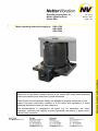
1
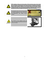
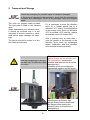
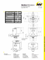
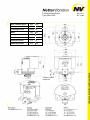
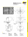
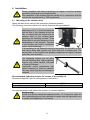
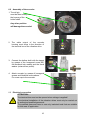
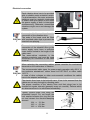
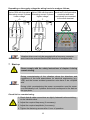
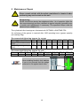
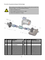
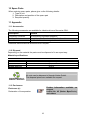
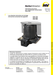
Operating Instructions for
Netter Vibration Drive
Series GSA
These operating instructions apply to:
Jan. 2012
BA No. 1264
Page 1/20
GSA 1702
GSA 2502
GSA 3502
Important note:
Before use of the Netter vibration drives of the series GSA read these operating
instructions carefully and keep them stored afterwards.
Netter GmbH does not assume liability for damage to property and persons if the
product has been technically modified or if the notes and regulations of these
operating instructions have not been observed.
This documentation is copyrighted. All rights, e.g. for translation into other
languages, reprinting and copying of these operating instructions or parts hereof
remain strictly reserved.
Contents
1
GENERAL NOTES
3
2
TECHNICAL DATA
4
3
DESIGN AND FUNCTIONING
5
4
SAFETY
6
5
TRANSPORT AND STORAGE
8
6
INSTALLATION
9
6.1
Mounting of the vibration drive
9
6.2
Assembly of the encoder
10
6.3
Electrical connection
10
7
START-UP
12
8
MAINTENANCE / REPAIR
13
9
TROUBLESHOOTING
15
10
SPARE PARTS
16
11
APPENDIX
16
11.1
Accessories
16
11.2
Disposal
16
11.3
Enclosures
16
Scope of supply
Check the packing for possible shipping damage.
If the packing is damaged, check the contents for completeness and
possible damage. In case of damage inform the transport agent.
Compare the scope of supply with the delivery note.
.
2
1 General Notes
Netter vibration drives of the series GSA
comply with the EC Machinery Directive
2006/42/EC, the Directive 2004/108/EC
relating to electromagnetic compatibility
and
the
Low
Voltage
Directive
2006/95/EC.
In
particular
the
standards
DIN EN ISO 12100, DIN EN 60529 and
EN 60034-1 have been observed.
Vibration
drives
vibrations.
generate
They can also be used in the food and
chemical industry if the respective
operating regulations of the user are
complied with.
Special features:
• 100% duty cycle
• Protection type IP 65
• Insulation class F
• High efficiency due to silicon electric
sheets
• Minimal installation dimensions
• Noise level ≤ 70 dB(A)
• Fitted with thermistor as a standard
• Earthing screw in the terminal box
circular
These vibration drives are used in Netter
dóêçShake shaking stations and shaking
tables.
Shaking stations of the series dóêçShake
are used for concrete compaction in
pre-cast part manufacturing plants.
Shaking tables loose, separate and distribute bulk material and mix liquids into
emulsions and suspensions.
In these operating instructions the following information and danger symbols are used:
DANGER
points out a possible danger which might result in death or serious injury if not avoided.
CAUTION
points out a possible danger which might lead
to personal injury or equipment damage if not
avoided.
HOT SURFACE
points out a possible danger which might lead
to personal injury or equipment damage if not
avoided.
IMPORTANT
Note containing especially useful information
and tips.
ENVIRONMENTALLY
points out the obligation to dispose of waste in
FRIENDLY WASTE
an environmentally friendly way.
DISPOSAL
3
2 Technical Data
Nominal voltage, nominal frequency:
The use of a frequency converter is mandatory for the
operation of the vibration drives!
Voltage and frequency as specified on the type plate.
Power supply with frequency converter:
At constant torque (linear Volt-Hertz curve) the frequency
converter may regulate the frequency between
0 Hz and 50 Hz
Type GSA 1702
0 Hz and 38 Hz
Type GSA 2502
0 Hz and 34 Hz
Type GSA 3502
(Observe maximum frequency on the type plate).
It must be ensured that the EMC Directive is complied with.
The operation of vibration drives of the series GSA with
frequency converters permits variable speeds.
IMPORTANT
Rotary speed ranges:
Type GSA 1702
Type GSA 2502
Type GSA 3502
maximal 750 rpm
maximal 580 rpm
maximal 510 rpm
The maximum speeds indicated on the type plate must not
be exceeded.
Ambient temperature:
0°C to +40°C
The ambient temperatures must not be exceeded or fallen
below. These values apply to operation with a duty time of
100%.
Vibration drives must not be used in hazardous areas.
Thermal overload protection:
GSA vibration drives are fitted with a PTC thermistor 130°C as a
standard.
Type
GSA 1702
GSA 2502
GSA 3502
Nominal
frequency
[Hz]
50
38
34
Max.
speed
[min-1]
750
580
510
4
Unbalance
[cmkg]
1.622
2.698
3.500
Centrifugal
force
[N]
50.000
50.000
50.000
The technical data of your vibration drive can be seen on the type plate.
Type designation
Duty time
Rotary speed
Centrifugal force
Voltage
Frequency
Current
Phases
Power
Insulation class
Manufacture year
Protection type
Serial number
Max. ambient temp.
For detailed technical data on the vibration drives see the Technical Data Sheets in the
middle section of this operating manual.
3 Design and Functioning
• The vibration drive of the series GSA
is an asynchronous motor.
• The motor shaft is made of heat
treated alloy steel.
− The stators of the asynchronous motors
are made of electrical sheet with a low
dissipation factor in order to achieve a
high efficiency at a low operating temperature of the motor.
• The
special
bearings
are
overdimensioned for excessive loads
− Motor protection
thermistor.
• The housings are made of
strength lamellar graphite cast.
by
• Rotary
speed
regulation
with
frequency converters is mandatory for
all units.
incorporated
high
• The paint finish is highly weatherresistant as well as resistant to abrasion, impacts and a wide variety of
chemicals. Colour: traffic black.
• The unbalance masses
separated from the drive.
5
can
be
4 Safety
Voltage-carrying or rotating parts can cause severe or fatal injuries.
DANGER
DANGER
The vibration drives are manufactured in accordance with the current EC
directives.
Assembly, installation, commissioning and maintenance must only be
performed by authorized qualified personnel.
During installation and operation of the vibration drives the directives and
regulations of the local associations for electrical engineering (e.g. VDE)
and the known accident prevention rules have to be complied with.
Changes to the device may affect the characteristics or even damage the
unit and cause the rejection of any warranty claims.
CAUTION
When working on the vibration drive it has to be safely disconnected from
the power supply. To do this, proceed as follows:
1. Switch off vibration drive
DANGER
2. Secure against being switched on again
3. Check for the absence of voltage
Use a suitable supply cable for the
installation. Connect cables and
protective conductors correctly.
DANGER
IMPORTANT
Circuit diagrams can be found in the
terminal box (see chapter 6.2 Electrical
connection).
The ends of the leads must be fitted
with insulated cable clips to prevent the
strands from splaying.
The maximum size of the cable clips is
AWG 16 for set screw M5.
The electric cables have to be installed carefully and it has to be ensured
that the cables are not worn through by vibrating parts.
The proper condition of the electric cables and the cable clips has to be
checked at regular intervals (as a rule every six months). Discovered
DANGER
faults have to be immediately eliminated.
Protect the cable against high temperatures, lubricants and sharp edges.
6
DANGER
DANGER
HOT
SURFACE
GSA vibration drives and other parts of the structure may come loose
due to vibration. Falling parts can cause injuries or damage to material.
Screw locks and/or Loctite or the like have to be used. Screw
connections have to be checked and possibly retightened after 1 hour of
operation and then at regular intervals (as a rule once a month).
The vibration drive must not be operated without unbalance cover! The rotating unbalances can cause severe
injuries!
The surface of the vibration drive can
reach such high temperatures that there
is a risk of burns.
7
5 Transport and Storage
Check the packaging for possible signs of transport damages.
In the event of damage to the packaging, check that the contents are
IMPORTANT complete and undamaged. If there is any damage, inform the shipping
agent.
The units are packed ready-to-install.
If it is necessary to store the vibration
The type plate is fixed on the vibration
drive for a longer period (up to a
drive.
maximum of 2 years), the temperature
When transporting the vibration drive,
in the storage room must not fall below
it should be ensured that it is not
+5°C or exceed +40°C and the relative
subjected to severe impacts or vibraair humidity must not exceed 60%.
tions which might damage the bearings.
After a storage time of more than 1
The device should be stored in a dry
year the grease in the bearing of the
and clean environment.
vibration drive must be exchanged
before installation and the vibration
drive must be tested electrically.
DANGER
The vibration drives must never be
placed directly on the encoder and
Use the transport lug in the mo- the terminal box, because the
tor shaft only for lifting the vibra- encoder and terminal box would be
tion drive.
damaged by it.
Vibration drives must always be
transported standing on the flange.
IMPORTANT
Always place sufficiently high
square timber blocks underneath
the flanges when setting the
vibration drive on the ground or
transporting it.
8
Technical Data Sheet
Type GSA 1702
750
min-1
Unbalance
1.622
cmkg
Centrifugal force
50.000
N
Mass
210
kg
Voltage
400
V
Frequency
50
Hz
Nominal current
3,5
A
Nominal power
2,55
kW
Max. rotation speed
contact surface
milled flat
Dec. 2011
No. 4506E
Technical Data Sheet
Type GSA 2502
580
min-1
Unbalance
2.698
cmkg
Centrifugal force
50.000
N
Mass
245
kg
Voltage
400
V
Frequency
38
Hz
Nominal current
3,5
A
Nominal power
2,55
kW
Max. rotation speed
contact surface
milled flat
May 2011
No. 4392E
Technical Data Sheet
Type GSA 3502
510
min-1
Unbalance
3.500
cmkg
Centrifugal force
50.000
N
Mass
273
kg
Voltage
400
V
Frequency
34
Hz
Nominal current
4
A
Nominal power
2,8
Max. rotation speed
kW
contact surface
milled flat
May 2011
No. 4393E
6 Installation
DANGER
During installation the safety instructions of chapter 4 and the accident
prevention rules have to be complied with!
The installation of the system must be carried out in compliance with the
local known regulations (e.g. VDE regulations).
6.1 Mounting of the vibration drive
Netter vibration drives can only be operated in horizontal position.
The following instructions have to be strictly observed during installation:
DANGER
The mounting surfaces must be
absolutely even (± 0,1mm evenness) so
that the feet of the vibration drives are
fully in contact with the surface and no
tensions occur in the housing when
tightening the fastening screws. There
should also be no paint residues or weld
penetrations on the surfaces. Tensions
in the housing can lead to mechanical
and/or electrical damage.
It is mandatory to use fastening screws of the quality 8.8 (DIN 931 or 933)
and secure them with counter nuts (DIN 934) and a suitable glue. The
screws have to be checked and possibly retightened at regular intervals
(generally once a month).
DANGER
The tightening torques can be taken
from the following table. Higher tightening
torques may cause fracture of screws
or tearing of threads.
Inadequate screw connections may
cause loosening of units by vibration.
This can cause injuries and damage to
material!
Recommended tightening torques for screws of the quality 8.8
(Screws as supplied, with no extra grease or lubrication):
Screw type
Torque
M 24
740 Nm
Use a torque wrench and tighten the screws in a crosswise pattern.
Retightening:
Screw connections should be retightened after 1 h of operation (after the
first commissioning) and then checked at regular intervals (generally once
DANGER a month) and retightened, if necessary.
9
6.2
Assembly of the encoder
1. The roll pin
must be fitted exactly into
the keyway of the
hollow shaft.
Any other position
will damage the encoder!
2. The cable output of the encoder
housing must show in the direction of
the terminal box of the vibration drive.
3. Connect the hollow shaft with the tappet
by means of the hexagonal screw M5,
the Nordlock lock washer and the thrust
washer (external hex profile).
4. Attach encoder by means of hexagonal
screws and Nordlock lock washers.
Fix screw cap to the encoder.
6.3
Electrical connection
ATTENTION:
The terminal box must not be opened when voltage is applied!
The electrical installation of the vibration drives must only be carried out
by authorized qualified personnel.
DANGER
The qualified personnel have to use only insulated tools that are suitable
for this area of application.
10
Electrical connection
Each vibration drive has to be provided
with a suitable motor protection switch.
For dual operation, the motor protection
switches must be mutually interlocked
to ensure that upon failure of one motor
the power supply of both is interrupted
DANGER
simultaneously. Otherwise uncontrolled
vibrations might occur and damage the
system.
Use only flexible cables for the
connection of the vibration drive.
IMThe ends of the leads must be fitted
PORTAN with insulated cable clips to prevent the
T
strands from splaying.
The conductors in the supply cable for
connection of the vibration drive to the
mains supply must have a sufficient
cross section suited to the length of the
cable used.
The green-yellow conductor is the
DANGER
earthing conductor and must be used
exclusively for connection to the earth
terminal.
When selecting the connecting cables, please consider the mechanical
demands on the cables due to vibration.
The recommended cable types for power supply operation with 400 V in
non-explosive atmosphere: rubber hose line H07 RN-F or oilflex cable
IMPORTAN 110 CY.
T
In case of other voltages or other environmental conditions the cables
have to be adapted accordingly.
The electric lines have to be laid with care. It has to be ensured that the
cables are not worn through by vibrating parts.
The proper condition of the electric lines and their plugs has to be
checked at regular intervals (generally every six months). Defects which
DANGER
are discovered are to be eliminated immediately.
Tighten junction plate nuts using the
prescribed torque. Do not forget the
lock washer between the ring and the
nut and reinsert the vibration-damping
element.
DANGER
M 4 ⇒ 3,1 Nm
M 5 ⇒ 6,1 Nm
M 6 ⇒ 10,4 Nm
11
Depending on the supply voltage the wiring has to be made as follows:
Terminal plan
The green-yellow
Series GSA with thermistor Series GSA with thermistor conductor is the protective
Alternating current 3-phase Alternating current 3-phase
conductor and must
Lower voltage
Higher voltage
exclusively be connected
to the earth terminal.
U
More terminal plans (e.g. for special voltages) on request.
Vibration drives must only be operated with a frequency converter
IMPORTANT and it has to be ensured that the EMC directive is complied with.
7 Start-up
Please comply with the safety instructions of chapter 4 during
commissioning.
CAUTION
During commissioning of the vibration drives the directives and
regulations of the local associations for electrical engineering (e.g.
VDE) and the known accident prevention rules have to be complied
with.
IMPORTANT
During initial commissioning the power consumption must be measured individually in all 3 phases and should correspond to the data on
the type plate.
Check list for commissioning:
1. Check that all cable connections are tightly fastened before switching
on the vibration drive.
2. Adjust the required frequency (if necessary).
CAUTION
3. Adjust the required amplitude (if necessary).
4. Tighten the fastening screws after 1 hour of operation.
12
8 Maintenance / Repair
Please comply strictly with the safety regulations in chapter 4 when
performing any service work on the unit.
CAUTION
DANGER
Retightening:
Screw connections should be retightened after 1 h of operation (after the
first commissioning) and then checked at regular intervals (generally once
a month) and retightened, if necessary. The specified torque must be
observed (see chapter 6.1)
The cylindrical roller bearings are lubricated with OPTIMOL LONGTIME PD2.
An exchange of the grease is required after 1000 operating hours (grease quantity
per bearing: 80g).
Recommended tightening torques for screws
Screw type
M6
M8
M10 M12
8.8 Tightening torque 10,4
25
51
87
[Nm]
12.9 Tightening torque 18
43
87
150
[Nm]
M14
140
M16
215
M18
300
M20
430
240
370
510
720
Recommended tightening torques for nuts
Nuts
M5
M6
M10
M12 M14×1,5 M18×1,5 M24×2 M30x1,5
Nm
5
9
45
70
130
270
650
1100
When installing Nordlock lock washers
it has to be ensured that the wedge
IMPORTANT surfaces lie flat against each other.
13
Procedure for grease exchange in the bearings:
When working on the vibration drive it has to be safely disconnected from
the power supply. To do this, proceed as follows:
1. Switch off vibration drive
GEFAHR
2. Secure against being switched on again
3. Check for the absence of voltage
Item Quantity Description
1
1
Housing
3
1
Rotor
5
2
Spacer
6
2
Inner ring of cylindrical
roller bearing
7
1
Flange Encoder
8
2
Rotary shaft seal
9
2
Cylindrical roller bearing
10
2
Rotary shaft seal
11
1
Flange unload
12
1
Incremental encoder
13
1
Unbalance
14
1
Lock washer
15
1
Terminal box
14
Item. Quantity Description
19
8
Socket head screw
20
8
Lock washer
21
1
Counter-sunk screw
22
6
Socket head screw
23
24
25
26
27
28
29
30
6
2
1
1
1
1
1
1
Lock washer
Seal ring
Druckscheibe
Socket head screw
Lock washer
Roll pin
Parallel key
Screw cap
9 Troubleshooting
ATTENTION:
Faults on vibration drives must only be repaired by authorized qualified
personnel.
Fault
Possible Cause
Vibration
Phase interruption
drive does
not start or is
running with Mains voltage too low
low speed
Wiring fault
Insufficient contact on a
connecting terminal
Phase interruption
Speed drop
under load
Incorrectly dimensioned
connecting cable
Overload
Mains voltage too low
One phase
without
current
Excessive
temperature
rise in the
stator
winding
Humming
vibration
drive
Phase interruption
Troubleshooting
Check fuse and
connecting cables
Check with terminal plan
Check connection in
Tighten terminal nuts
terminal box
Check fuse and
connecting cable
Check cable
cross-section
Check setting of
unbalances
Check mains voltage and
cable cross-section
Replace fuse or
connecting cable
Replace cable
Reduce unbalance
Correct mains voltage,
replace cable
Check connecting cable Replace cable
Wiring fault
Overload
Check with terminal plan
Mains voltage too low
Check mains voltage and Correct mains voltage,
cable cross section
replace cable
Phase interruption
Check fuse, mains
voltage and connecting
cable
Phase interruption
Overload
Short circuit in the winding
High power
Natural resonance range of
consumption the vibration system
Impacts
Bearing too
hot
Replace fuse or
connecting cable
Check mains voltage and Correct mains voltage,
cable cross section
replace cable
Turn-to-turn fault in the
stator winding
Circuit
breaker fails
when
switched on
Remedy
Too much grease in the
bearing
No grease in the bearing
Correct mains voltage,
replace fuse or cable
Replace vibration drive
Check fuse and
Exchange fuse or caconnecting cables
ble
Check setting of
Reduce unbalance
unbalances
Exchange vibration drive
Check power
Stiffen the device
consumption
Check power
Reduce force of
consumption
vibration drive
Fastening loose
Retighten screws
Apply correct quantity of grease Optimol
Longtime PD2
Apply correct quantity of grease Optimol
Longtime PD2
Foreign matter in the
bearing
Clean or replace bearing
15
10 Spare Parts
When ordering spare parts, please give us the following details:
1. Type of unit
2. Description and position of the spare part
3. Required quantity
11 Appendix
11.1 Accessories
The following accessories are available for vibration drives of the series GSA:
Description
Remark
Frequency converter
for frequency-regulated operation
Braking devices
permit a rapid slow-down of the vibration drives
Encoder
zur Positionsbestimmung der Unwucht
Additional electrotechnical accessories on request.
11.2 Disposal
Depending on the material the parts must be disposed of in an expert way.
Material specifications:
Steel
Aluminium
PTFE, PU, VITON
Copper with resin
ENVIRONMENTALLY
FRIENDLY DISPOSAL
GSA
Rotor, case, unbalance, flange, bearing, screws, discs and nuts
Type plate
Seals, terminal box
Winding
All units can be disposed of through Netter GmbH.
The disposal prices are available on request.
11.3 Enclosures
Further information available on
request
Leaflet No. 42 (Netter dóêçShake),
and others
Enclosure (s):
Declaration of Incorporation
16