1
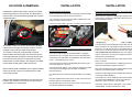
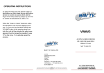
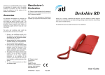
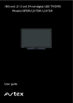
OPERATING INSTRUCTIONS
SWITCH 1 on activates RGB input
SWITCH 2 on activates AV1 input
SWITCH 5 on activates Rear Camera
SWITCH 6 on activates Factory Navigation.
To select the your added RGB source (if activated) to
appear on the screen you need to press the NAV button
on the display controls once, pressing the NAV button a
second time will select the A/V source (if activated)
Pressing the NAV button a third time will select the
factory system (if activated). The audio will change from
factory audio i.e. radio to that of the added A/V source
at the same time as the video is selected. If RGB is not
activated then pressing the NAV button once will select
the A/V input, and pressing a second time will select
factory system.
AVMMI
A/V INPUT
AUDI A4 / A5 / A6 / A8 / Q7 MMI
E.g.
If RGB input only is needed then switch 1 should be
on and all others off.
Without TV Tuner
If AV1 input only is needed then switch 2 should be
on and al others off.
NAV TV (UK) LTD
If both RGB and AV1 are needed then both switch 1
and 2 should be on.
NAV TV (UK) LTD
Unit R4
Capital Business Park
Wentloog
Cardiff
CF3 2PU
NO OTHER SWITCHES ARE NOT USED IN THIS
APLICATION.
Telephone: + 44 (0)870 801 0440
Fax telephone: + 44 (0)870 801 0441
[email protected]
Disclaimer
NAV TV (UK) Ltd is not liable for any incidental, consequential or indirect damages. In case of erratic behavior of the vehicle’s electrical
system please disconnect the NAV TV product and contact our technical support Team. NAV TV (UK) Ltd does not assume liability for any
diagnostic fees.
e11*72/245*95/54*3583*00
RoHS 2002/95/EC—2002/96/EC
LOCATION & REMOVAL
Installation is made at the screen control unit located
behind the glove box in Q7 and A8. The Glove Box is
secured with 3 screws at inside top edge and 3 screws
outside at bottom.
INSTALLATION
Power and other connections
Power connections are made at the passenger side fuse holder
and at the RED plug from the screen control unit.
12v+ Accessory can be found at the RED 10 AMP fuse in fuse
holder C (black), see photo below.
INSTALLATION
Connect the supplied optical cables to the optical cable from
the screen control unit as follows
Insert OPTICAL cable into supplied cable jointing connector
and car plug to create loop, take note of the arrows on the
plugs see diagram below.
Connect the RED cable to the 12v+ Accessory (in Fuse holder)
The screen control unit on new A4 and A5 is located
behind the CD changer and heater controls. The CD
changer is removed with AUDI removal keys.
The screen control unit is secured with 2 screws.
Remove these and unplug the unit. Next remove the
mounting plate (also 2 screws) cut the tie securing the
loom, and re-route the loom to above the mounting
bracket then re-fit the bracket. This will give you easier
access when re-fitting the screen control unit.
When re-fitting (after installation of the supplied cables)
mount the screen control unit upside-down to make
cable routing easier.
Remove the dashboard side panel to access the fuse
holders, this is where you can find 12v+ (Accessory)
see installation for more details.
The Following Connections are made at the RED plug removed
from the screen control unit
Connect the WHITE cable to the WHITE/GREY or (WHITE /
YELLOW A8 / A6 / A5) Cable found in pin 16 of the RED plug
Connect the YELLOW cable to the RED/YELLOW cable found
in pin 1 of the RED plug (12v+ Perm)
Connect the BLACK cable to the BROWN cable found in pin 2
of the RED plug (12v– Ground)
Connect the BLUE cable to a 12v+ supply to trigger the reverse
camera input (reverse light) (No Dip switch is needed for
Reverse Camera)
Plug this loom into the interface (marked POWER 1 & POWER
2)
Plug the supplied lead into the screen control unit, and into the
interface (marked TO CONTROL UNIT)
Plug the black plug (removed from the screen control unit) into
the interface (marked TO SCREEN)
You will need to insert the (out) fibre optic cable from the
factory connector into the supplied Jointing connector an
press shut, you will need to push out the small locking insert
to remove it, You will then need to insert the other supplied
cable (marked into the interface) into the now empty (out)
location of the factory connector and replace the small
locking insert. (shown above)
Note; Do not remove the fibre optic cable marked in from the
factory connector.
When loop is complete insert the supplied plug into the
interface (marked MOST OPTICAL IN/OUT)
Plug in the supplied loom to the socket marked AV INPUTS
and insert your VIDEO signals as required.
Insert your AUDIO signals to the RED/BLACK cable sockets
in the plug marked POWER 2.
The interface can use an RGB input this loom is inserted into
the socket marked RGB INPUT and if used will need
SWITCH 1 down. The loom is colour coded,
*Red=Red, *Green=Green, *Blue=Blue, *Sync=White,
*Shield=Black, *Guide Voice/Talk over= Grey.