1
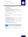
OMS Antriebstechnik OHG
Bahnhofstraße 12
36219 Cornberg
Deutschland
Telefon: +49 (0) 5650 / 969-0
Telefax: +49 (0) 5650 / 969-100
Operating Instructions
According to Annex I of the EC Directive 98/37/EC Mechanical Equipment
– Part 1.7.4
Elevator Machine
Model: omsHypodrive AZHP1
Please archive this document for future reference
OMS No.
Date of Manufacture
Month / Year
Operating Instructions AZHP 1
(Technical changes reserved – Last Changes 09/2005)
List of Contents
Page
1
INTRODUCTION
4
2
SAFETY INSTRUCTIONS FOR OMS ELEVATOR MACHINES
5
Applicable Use
None Applicable Use
Warranty and Liability for the Elevator Drive
Dangers, that are associated with the Elevator Drive
Instructions for Safe Use
Requirements and Qualification - Installation and Maintenance
Personnel
General Information
5
6
8
8
9
2.1
2.2
2.3
2.4
2.5
2.6
2.7
3
3.1
3.2
3.3
3.4
3.5
3.6
4
4.1
4.2
5
5.1
5.2
5.3
5.4
6
6.1
6.2
6.3
6.4
6.5
6.6
6.7
CONSTRUCTION AND FUNCTION
Technical Data
Noise Emission Information
Manufacturers Identification Plate
Modules and Additional Parts – Spare Parts
Alternative Configurations
Gearbox Variations and Applicable Mounting Configurations
TRANSPORT AND STORAGE
Transport
Storage
PREPARING FOR USE
Assembly
The Brake
Emergency Release – Installation and Operation
Installing the Rope Clamp
9
9
10
11
11
11
12
12
13
15
15
15
17
17
20
21
22
REGULAR USE AND MAINTENANCE
23
Recommended Routine Maintenance
Error – Troubleshooting Errors
Gearbox Oil
Replacing the Traction Sheave
Brake Maintenance
Replacing the Incremental Encoder
Replacing the Motor
23
24
24
27
28
30
31
Page 2 of 47
Operating Instructions AZHP 1
(Technical changes reserved – Last Changes 09/2005)
7
7.1
7.2
8
A
B
C
D
E
F
DISASSEMBLY
Disassembly of the Elevator Drive
Scrapping the Elevator Drive
ADDENDUM
Technical Data Oms Elevator Machine AZHP 1
Dimensions Sheet Elevator Machine AZHP 1
Electrical Connections
Technical Data Disc Brake
Traction sheave
Technical Releases, Declaration of Conformity
32
32
32
33
34
35
36
39
44
46
Page 3 of 47
Operating Instructions AZHP 1
(Technical changes reserved – Last Changes 09/2005)
1 Introduction
These instructions include pictograms for commenting on Warnings and Safety Issues.
Application Tip: Additional Comments and
Information, no danger involved
Warning: of a general risk for the machine or a
human safety hazard
Warning: of dangerous currents, a liability of
serious damage to health or death
Warning: of hot surfaces, a liability of serious
damage to health and / or serious material
damage
Warning: of crush injuries, a liability of serious
damage to health
Warning: of drawing in, a liability of serious
damage to health
Warning: DANGER
Risk for the machine or a human safety hazard,
a liability of serious damage to health or death
Page 4 of 47
Operating Instructions AZHP 1
(Technical changes reserved – Last Changes 09/2005)
2 Safety Instructions for OMS Elevator Machines
2.1
Applicable Use
The OMS-Elevator Machine AZHP 2 is for operating electrically driven sheave drive
elevators for passengers or goods according to EN 81-1. The installation and use of
the AZHP 2 for other purposes is not applicable. The OMS ANTRIEBSTECHNIK OHG
are not liable for personal injury and or damage resulting from none applicable applications.
All Planning, installations and maintenance work may only be carried out by qualified personnel. Qualified personnel are such who having studied for qualifications,
or are experienced, or have received instruction and have the knowledge relating to
the relevant standards and directives, safety regulations and local knowledge required to install and maintain the machine and be able to recognise and access the
risks appertaining to this machine. (Qualified Personnel, as defined in IEC 364).
This OMS – Elevator Drive is applicable to the 9th Directive of the Machine and
Product Safety Law (9. Verordnung zum Geräte- und Produktsicherheitsgesetz (Maschinenverordnung) and the 98/37EC Machine Directive. It is part of a plant that it is to implemented in an elevator system and is therefore not liable for CE certification. The
required manufacturers release is included within these instructions (Page 47).
The commencement of regular use is not permitted until the erection (according to
Elevator Directive 98/16 EC) has been completed in the pre determined elevator
system and the CE label has been applied to the elevator to show that the safety
requirements have been fulfilled for the machine as supplied by the manufacturer.
All other required regulations and certificates (e.g. applicable to general use, maintenance and inspections) remain in force.
The drive manufacturer only respects the warranty for operation and safety of the
drive if it is has been erected, maintained and operated according to the printed
specifications supplied individually with each drive. The warranty is void if the parameters outlined in the operating, maintenance and control documentation have
been exceeded. An incorrect installation or incorrect use of the system, and or violation of the standards outlined above, lead to a complete and absolute none liability of the drive manufacturer.
The motors should only be used in conjunction with frequency converters.
Customer supplied frequency converters must be set up according to their instruction sheets, in order to comply with the requirements of the OMS-Elevator Machine.
Page 5 of 47
Operating Instructions AZHP 1
(Technical changes reserved – Last Changes 09/2005)
The OMS-Elevator Machine AZHP 1 is for operating elevators and has been designed for installation in an enclosed area (e.g. elevator shaft or machine room).
OMS Drives may only be stored, erected and run in dry closed areas. The IQ/OQ
representative and the user must ensure that adequate measures are taken to avoid
a contamination with building dust and or dirt.
The machine may only be stopped by the frequency converters and with the machine brake.
OMS-Elevator machines may only be operated when in technically good condition
and within the parameters as described by OMS.
Applicable use also includes the following:
• Working according to the supplied instructions,
• Observing the regulatory safety and environmental requirements,
• Adherence and observance of the Elevator documentation and regulations.
2.2
None Applicable Use
OMS Drives may not be operated in potentially explosive or environmentally aggressive areas.
The double circuit disc brake is only designed for a limited number of emergency
stops. It’s use as a stand operation brake is not permissible.
Further operation is not permissible once the pre determined wear points have been
achieved.
Permissible Limits:
•
•
•
•
•
max. Motor Speed: refer to technical documentation;
max. Drive Wheel Load: refer to technical documentation;
max. Number of Starts / Hour = 240;
Local ambient temperature during operating min.: 5° C, max.: 40° C;
The technical data and specifications on the Motor Data Label are only valid for
an installation height up to h ≤ 1000m over NN.
• Max. rel. Humidity: 85% at 20°C (none condensing)
None applicable use also includes the following:
- Dry operation without oil or use of a lubricant other than specified
- Securing the drive with bolts weaker than those specified
- Opening the Gearbox when installed on the drive
Page 6 of 47
Operating Instructions AZHP 1
(Technical changes reserved – Last Changes 09/2005)
Important:
•
All work related to; Transport, Electrical Connections, pre-Service
Checks and Maintenance of the Drive System must be carried out by
qualified technicians. Incompetent work can lead to serious personal
injury and / or damage.
Warning ! Special Notes appertaining to AZHP 1:
•
The machine is very efficient and has a very low natural friction
rate. The machine operates immediately after the brake has been
released.
•
During the installation of the Safety gear , it is important that the Machine Brake
is available and that the brake can be operated at any time as and when required.
•
Using the elevator when the Emergency Brake is not operable is forbidden. The
operator is responsible for the welfare and safe running of the elevator and all
persons within.
•
Regular checks of the Safety gear and the Buffer must be carried out according
to EN 81-1 Appendix E with an empty cabin and at reduced speed.
Regular checks should not cause wear or stress which could lead to a lessening of
elevator safety. Due to the inherent high level of efficiency, the drive should not
be tested at speeds higher than vmax. ≤ 1,0ms-1. Otherwise serious damage could be
caused to the drive and/or other parts of the elevator system.
Alternatively, the checks can be performed using test weights and testing at
nominal speed.
•
The cabin may only be pulled out of the Safety gear by moving the cabin in the
opposite direction that caused the Safety gear to holt the elevator. The elevator
Machine may only be operated in a situations with the maximum loads as given
by the machine specification. All other methods, which would put additional static or dynamic loads on the for example the Traction sheave , Motor or Gearbox
are forbidden. OMS will not respect any warranty claims resulting from practices
other than those laid out in this document.
•
Ensure that the motor does not rest on or against the frame. If this should be the
case, take appropriate action to remedy to free the motor. Take care to inspect
the motor and the frame on each installation and document your actions.
Page 7 of 47
Operating Instructions AZHP 1
(Technical changes reserved – Last Changes 09/2005)
2.3
2.4
Warranty and Liability for the Elevator Drive
•
The drive manufacturer only respects the warranty for operation and safety of the
drive if it is has been erected, maintained and operated according to the printed
specifications supplied individually with each drive.
•
The warranty is void if the parameters outlined in the operating, maintenance and
control documentation have been exceeded.
•
The customer is responsible for the qualified installation of the drive by certified
personal.
•
If damage or other problems are found on the elevator or the drive, then the system must be disabled, otherwise the operator will be liable for all damage and injury appertaining thereto.
•
An incorrect installation or incorrect use of the system, particularly with respect
to the forbidden procedures outlined above, lead to a complete and absolute
none liability of the drive manufacturer.
•
This is also applicable, when after damage has occurred, the operator and/or the
installer and /or the maintenance company cannot supply a fully documented list
of procedures relating to the erection, testing, maintenance and SOP’s of the elevator (Elevator Book etc).
Dangers, that are associated with the Elevator Drive
Our elevator drives are at the cutting edge of technology and are delivered in a
safe operating configuration. Any changes made by that customer or his operative
that may affect the inherent safety of the elevator drive are not permissible.
The Drive Sheave and the Hand Wheel of the AZHP 1 are delivered by OMS without
a safety cover and may only be operated in a secure Machine Room. Take care
when working the Machine Room that an adequate safety distance is maintained
away from the moving parts (yellow).
The elevator supplier is responsible for installing safety shields if required.
Page 8 of 47
Operating Instructions AZHP 1
(Technical changes reserved – Last Changes 09/2005)
2.5
Instructions for Safe Use
If changes are observed during the service lift of the machine, e.g. wear, ageing etc.
then the machine should be serviced and the changes dealt with, according to the
OMS General- and Maintenance Instructions.
The gearbox may only be opened by OMS at our factory site; the warranty will otherwise become invalid.
2.6
Requirements and Qualification - Installation and Maintenance Personnel
All installations, maintenance work and repairs on the electrical parts of the machine may only be carried out by qualified personnel.
Qualified personnel are such who having studied for qualifications, or are experienced, or have received instruction and have the knowledge relating to the relevant
standards and directives, safety regulations and local knowledge required to install
and maintain the machine and to be able to recognise and assess the risks appertaining this machine. (Qualified Personnel, as defined in IEC 364).
OMS recommend that the technical personnel acquaint themselves with the machine before it is erected and taken into service. Please read the General- and
Maintenance Instructions carefully, these instructions will aid you to find mistakes
and technical deficiencies during the installation and operating life of the machine.
2.7
General Information
Should damage occur during transport, or should the machine appear during erection to have errors or be damaged, please contact OMS and inform us of the damage or error.
In case of damage caused by water, please contact OMS.
A decision as to whether the damage or error can be rectified on site or not, can
first be taken after the customer has contacted OMS. OMS will then decide if the
machine can be taken into service or whether the machine should be returned with the original packaging – to OMS.
Please retain the original packaging until after the machine has been taken into
service.
OMS will not accept responsibility for the correct installation and function of the
elevator in the shaft.
The responsibility for the correct installation and function of the elevator in the
shaft lies with the elevator supplier and / or the elevator operator.
Page 9 of 47
Operating Instructions AZHP 1
(Technical changes reserved – Last Changes 09/2005)
3 Construction And Function
Due to the high efficiency ratio of approx. 92% the machine generates little excess
heat, this ensures that the modules and aggregate parts and electronics are not exposed to excessive temperatures and therefore a detrimental effect – ageing and
wear – on these parts due to temperature influence is kept to a minimum.
Incremental Encoder:
Between the HandWheel and the Motor
Motoranordnung:
stehend oder liegend,
rechts oder links
Disc Brake:
Between the Motor and
the Gearbox
Traction Sheave:
Drive Flange
on the Gearbox side
Getriebegehäuse
mit 3-seitigen Standund Anflanschflächen
Fig. 1: OMS-Elevator Machine AZHP 1, General Layout
Page 10 of 47
Operating Instructions AZHP 1
(Technical changes reserved – Last Changes 09/2005)
3.1
Technical Data
The efficiency of the OMS-Elevator Machine, relationship to the Elevator Cabin (1:1
or 2:1), Gearbox Version Specification, and possible installation constellations can
be found in the Appendix:
„Technical Data OMS – Elevator Machine AZHP 1“.
All measurements and fitting details for the OMS Elevator Machine can be found in
the Appendix:
„Dimensions Sheet – Elevator Machine AZHP 1“.
3.2
Noise Emission Information
All OMS elevator machines are subjected to a thorough noise emissions test before
leaving our factory site.
The test is conducted according to DIN EN ISO 11200 at a mean distance of 1 meter
to the machine surface.
Test procedure:
The machines are driven through Frequency Converters, the actual level of effort
reflects the known torque load and the drive speed.
When working to the given limits, the machines emit the following noise emission
parameters.
Machine
AZHP 1
Max. Sound Pressure Level LpA in dB(A)
< 61,0 at < 1.500 min–1
If you have any further questions regarding noise emissions, please contact OMS.
3.3
Manufacturers Identification Plate
The following information can found on the manufacturers identification plate. For
Example:
OMS ANTRIEBSTECHIK OHG
36219 CORNBERG
GERMANY
AZHP 1-15-23T-K405-010-A1
OMS Nr. - Baujahr xxxx-mmyy
OMS-Auftrag:
xxxxxx
Kommission:
xxxxxxxxx
Übersetzung:
14,67/1
Model:
AZHP 1
Ratio:
15
Motor type:
23
Encoder:
T
Traction sheave:
K405
Brake type:
010
Mounting Configuration:
A1
OMS-No. - xxxx- Month Year
MMYY
Page 11 of 47
Operating Instructions AZHP 1
(Technical changes reserved – Last Changes 09/2005)
3.4
Modules and Additional Parts – Spare Parts
The OMS-Elevator Machine AZHP 2 consists of:
•
•
•
•
•
Gearbox complete
Motor, complete with Incremental Encoder (between Hand wheel and Motor
Cover)
Brake system, complete
Traction Sheave
Safeguard device against Rope jumping (2-x)
Optional:
•
Rope Clamp
•
Lever System (2-x, each for opening one Brake Circuit manually)
•
Traction Sheave Brake, a safety item for controlling the speed of an ascending cabin as specified in EN 81
3.5
Alternative Configurations
The elevator machines can be supplied with the following alternative configurations:
•
•
•
•
•
•
Electric motors : various sizes (optional fan less)
Inkrementalgeber mit unterschiedlichem Signalausgang: SINUS, HTL, TTL
Incremental Encoder with various signal outputs: SINUS, HTL, TTL
Disc Brake: various torque ranges and electrical controls, with or without release levers
Traction Sheave: various diameters (320, 400, 450mm, others optional)
Safeguard device against rope jumping: Various fitting lengths, corresponding to the Traction sheaves, are available
Page 12 of 47
Operating Instructions AZHP 1
(Technical changes reserved – Last Changes 09/2005)
3.6
Gearbox Variations and Applicable Mounting Configurations
The OMS Elevator Machine AZHP 1 can be supplied in three different constellations.
Looking towards the Drive Shaft and the Traction Sheave (dotted), these are as follows:
Version A : Drive Shaft to the left of the longitudinal axis of the Motor
Additionally, common to all three versions, the Motor can be positioned vertically
erect or lying horizontally, above or below, with respect to the gearbox.
The following diagrams (2-4) show these variations.
According to the position, the Oil Dipstick and or Air Bleeder Valve will be found on
the highest position on the Gearbox Casing).
Fig. 2 – A 1
Fig. 3 – A 2
Motor horizontal, laid, above
Fig. 4 – A 3
Motor horizontal, laid, below
Page 13 of 47
Operating Instructions AZHP 1
(Technical changes reserved – Last Changes 09/2005)
Comments:
The standard position of the Terminal Connector Box on the Motor frame is in the
direction of the Brake solenoid, but can be rotated with the Motor by 90° or 180°.
To rotate the connector box, the motor fixing bolts must be unscrewed. Beforehand, disconnect the electrical supply and secure the machine against an unintentional power input. After repositioning the motor with the connector box, the bolts
must be diagonally re-tightened (50Nm).
If the force acting on the cable has a torque component which is perpendicular to
the direction of the Gearbox fixing bolts, then an additional bracket must be used
that supports the drive unit in this perpendicular direction, thus preventing the fixing bolts from being adversely affected by the sheer strength forces due to the elevator load. (If you have any questions on this issue, please contact OMS).
fastening
holes
Bracket
Force
Fig. 5: Additional Bracket
To ensure adequate lubrication and Gearbox efficiency, the elevator
machine may only be erected as ordered.
Page 14 of 47
Operating Instructions AZHP 1
(Technical changes reserved – Last Changes 09/2005)
4 Transport and Storage
4.1
Transport
All elevator machines are inspected and passed prior to leaving our factory site.
When you accept delivery of your machine, please check the packaging for signs of
exterior damage. If you find damage which appears to have been caused in transit,
then please document this damage in the presence of the delivery agent. The machine may not be taken into service.
The Machine leaves the OMS factory in an Oil tight state. If the Machine has to be
transported after having been installed, then the oil Dipstick and/or Air Bleeder
Valve must be removed and replaced with the original OMS Oil Sealing Plugs. If the
plugs are not available, please order new sealing plugs from OMS.
The weight of the machine (without traction sheave) can be found in the table on
page 34. The weights of the traction sheaves can also be found on this page.
4.2
Storage
The Elevator Machine must not be stored outside and may not be exposed to outdoor weather conditions. If it is planned to store the machine for a longer period of
time before installing it, then the measure must be undertaken to ensure an adequate conservation of the machine.
A)
Up to 3 Months Storage:
No special storage requirements.
Before the Elevator Machine is installed the following points should be observed:
• All the Brake Parts must be inspected (activate the Brake in case there should be
light corrosive spots on the Brake Drum).
• Turn the Machine a few times by hand, (to ensure that the Motor Bearings are
evenly greased).
B)
Up to 18 Months Storage:
If it is planned to store the machine for a longer period of time before installing it,
then the Machine can be ordered with the optional conservation kit. The Machine is
then treated in the OMS factory and packed in a humidity proof yellow plastic foil.
If this wasn’t the case, then:
• At the latest, after six months Storage the Gearbox must be filled to the highest
bolt hole with Oil.
• Warning: Oil Type: See the yellow label; only use one sort of Oil.
Page 15 of 47
Operating Instructions AZHP 1
(Technical changes reserved – Last Changes 09/2005)
• After filling with Oil, the Machine must be packed in a humidity proof (yellow)
foil: (this foil can be ordered from OMS).
• Dry Storage is required
Before the Machine is installed:
• Reduce the Oil Level! to the standard level (ref. Chapter 6.3.1).
• All the Brake Parts must be inspected (activate the Brake in case there should be
light corrosive spots on the Brake Drum).
• Turn the Machine a few times by hand, (to ensure that the Motor Bearings are
evenly greased).
• Install the Machine (Ref. Chapter 5. Preparing for use)
C)
Longer than 18 Months Storage:
Optional factory conservation or procedures as in: B) Up to 18 Months Storage
Dry Storage is required
Before the Machine is installed:
• Change all the Gearbox Oil. Take care to use the correct type of Oil and observe
the Oil Level as outlined under: 6.3.1 and 6.3.3.
• All the Brake Parts must be inspected (activate the Brake in case there should be
light corrosive spots on the Brake Drum)
• Turn the Machine a few times by hand, (to ensure that the Motor Bearings are
evenly greased).
• If the Machine cannot be turned by hand, or the movement is stiff, then the
Motor Bearings may have to be replaced.
• Install the Machine (Ref. Chapter 5. Preparing for use)
After a lenghty storage period, the manufactures warranty will
have run out. If a further warranty period is required, then the
Machine may be returned to OMS to be refurbished (new
Bearings etc.), this will incur some expense for the customer.
Damage, that has been caused by negligible handling is not covered by our warranty specification.
Page 16 of 47
Operating Instructions AZHP 1
(Technical changes reserved – Last Changes 09/2005)
5 Preparing For Use
5.1
Assembly
It is important that the planned frame or foundation for the elevator machine(s)
has been calculated with an adequate reserve.
The frame must be stiff enough to resist the tension- and torque stresses that will
occur during normal operation.
5.1.1 Elevator Machine, complete
1. Befestigen Sie die Maschine in der gewünschten Position über die vier Befestigungsgewinde in den Getriebefüßen. Die Einschraubtiefe entspricht der Gehäusestärke.
Bolts :
M 16 in Quality 10.9
200 Nm
Torque:
If required, supporting brackets and distancing plates should be used.
(see examples, Fig. 5).
Pre Use Requirements:
Exchange the labelled sealing plug on the Gearbox Casing with the supplied Oil
Dipstick or the supplied Air Bleeder Valve. Take care to observe the correct positioning of the Gearbox (See Figs. 2-4). Retain the sealing plug for possible future transportation of the Machine.
Important:
The Gearbox has been sealed against oil leakage during transport. The Gearbox is
airtight due to the sealing plug(s). If the Gearbox were to be taken into use with
the sealing plug(s) in place, then excess pressure may build up in the Gearbox,
eventually causing the Gearbox to leak – oil will be pressed out through the Shaft
Gaskets.
The Oil Dipstick does not seal the Gearbox.
Electrical Connections
Only qualified personnel may open the Terminal Box on the Motor
and connect the machine to the electrical supply. Only qualified
personnel may carry out repairs and service work on the electrical
parts of the machine.
Disconnect the main switch beforehand and secure the switch against unintended
operation!!
The Safety Rules for the Construction and Erection of Elevators“ according to DIN –
EN 81-1 must be observed at all times.
Page 17 of 47
Operating Instructions AZHP 1
(Technical changes reserved – Last Changes 09/2005)
Important:
The electrical system for the machine has been designed according to: EN 60 204 –
1.
In order to ensure failure free function of the machine, it is recommended that
all wiring should be shielded according to the standard EMV regulations. Avoid
ground loops when connections include multiple shields.
Procedure:
1. Motor:
The electrical connections should be connected as per the diagram in the Motor
Terminal Box. (See also: Appendix, Electrical Connections). Should a different wiring
exit position be required, the Terminal Box can be turned by loosening the internal
fixing screw and repositioning the Terminal Box.
Please take care when adjusting the fine wiring of the temperature monitor
switches.
2. Frequency Converter:
The connection and setting up of the Converter together with the OMS-Elevator
Machine must be carried out according to the instructions supplied with the Converter.
3. Incremental Encoder:
The Incremental Encoder (between Motor Cover and Hand wheel) is supplied with a
5m-shieded cable and a 2 row 15-pin connector, which should be connected to the
Frequency Inverter. The shielding is wired to the plug casing, PIN 12 and the Incremental Encoder.
According to the Incremental Encoder used, the wiring for the connector can vary
(See Appendix, Electrical Connections, Incremental Encoder).
Should the Connector on the Frequency Inverter be non-compatible, adapters and
longer cables are optionally available (See Appendix).
4. Disc Brake:
The connection of the Brake Magnet (Two Circuit Disc Brake), should be carried out
in respect to the local elevator configuration:
a) If the machine is accessible in a service room, then both Brake Magnet Circuits
may be connected to a single Control Module.
b) in case the machine is installed in an inaccessible position, and if emergency
control and checking of each circuit will be done purely electrical, then each
Magnet may be connected to two separate Control Modules, which in turn may
be individually wired (for checking the individual Brake Circuits, See 5.2.2-b1)
Page 18 of 47
Operating Instructions AZHP 1
(Technical changes reserved – Last Changes 09/2005)
5.1.2 Safeguard Device against Rope Jumping
The safeguard devices must be fitted to the elevator machines. The
Rope Jump Devices can be fitted after the cables have been installed.
They must be adjusted so that they do not rub or bind and there must
be a gap between the Ropes of between max. 1 – 2 mm.
The safeguard device against rope jumping is supplied twice and consists of the
following components each:
Bolt
Safeguard device against
rope jumping
cheese-head screw
M16 x 25
Hex screw
M10 x 25
Fig. 6: Module, safeguard device against rope jumping
Adjustment according to the Drive Sheave diameter:
1. Loosen the screw M10 x 25 and push the Safety Bolt along the slit to the required position.
Page 19 of 47
Operating Instructions AZHP 1
(Technical changes reserved – Last Changes 09/2005)
5.2
The Brake
5.2.1 Setting the Brake
The Brake has been set up by OMS. The Brake set up should not be altered. Before
taking the AZHP 1 into service, the function ability of the Brake should be checked.
If the Brake should show any adverse behaviour, then we recommend changing the
complete Brake System.
See the notes: „Erection and Instructions for the Disc Brake“.
5.2.2 Control, both Brake Circuits:
Comments: The procedure for conducting the final check of the brakes as part of
the Elevator Acceptance Test is not described in detail here. Please refer to the relevant safety regulations and requirements.
The following points a) to b2) are only relevant, when an individual control of each
Brake Circuit is required.
a) For an accessible machine:
Is the machine accessible in a Service Room or Elevator Shaft, then it is possible to
laterally open the Brake Levers and simply check the movement of each Brake
Lever. (See the technical description of the Brake system in the Appendix)
b) For an inaccessible machine:
If the machine has been installed in an inaccessible position, then an electrical or
mechanical Remote Control will be required:
b1) External electrical Remote Control:
The Solenoids of the Brake Magnet can be individually activated. Thus, it is possible
to individually operate the two braking circuits
b2) Mechanical Remote Control:
To check the Brake Levers individually two linkages can be optionally supplied. A
bracket is fitted to the Gearbox Casing to support the linkages. The linkages must
be ordered together with the AZHP 1 for the brake.
Page 20 of 47
Operating Instructions AZHP 1
(Technical changes reserved – Last Changes 09/2005)
5.3
Emergency Release – Installation and Operation
The required Emergency Instructions – that must be placed adjacent to the Emergency Release – are not described here. Please refer to the relevant safety regulations and requirements.
a) for an accessible machine:
Is the machine accessible in a Service Room or Elevator Shaft, then the Brake can
be opened with the standard Lever.
If required the Elevator Cabin can be moved by turning the Hand Wheel on the Motor.
b) By Remote Control:
If the machine has been installed in an inaccessible position, then an electrical or
mechanical Remote Control will be required:
b1) external Electrical Remote Control:
If an Emergency Power Source is available, then the Electromagnets and the Motor can be wired into the Emergency Power.
b2) mechanical Remote Control:
The brakes can be opened using the (optional) external Brake Lever linkages.
Page 21 of 47
Operating Instructions AZHP 1
(Technical changes reserved – Last Changes 09/2005)
5.4
Installing the Rope Clamp
During repair and revision periods a (optionally available) Rope Clamp can be fitted,
so avoiding Rope slippage through the Traction Sheave.
The Rope Clamp must be fitted to one of the openings in the Traction Sheave. (See
Fig. 7). Take care, that the lug on the Clamp Bracket snaps behind the frame that
follows the opening. Thus preventing a slipping of the Rope Clamp after releasing
the Locking Bolts.
Both Locking Bolts should be tightened so that the inner and outer bars lie parallel
to each other. The inner bar is supported by the frame thus ensuring that all the
ropes equally support the resulting forces.
Outer bar
Traction Sheave
Window in Frame of
the Traction Sheave
Inner bar
Fig. 7: Rope Clamp, fitted to the side of the Traction Sheave
When using a Rope Clamp ensure that:
1. It cannot collide with other parts of the machine.
2. It cannot get tangled in the vertical elevator ropes.
3. It cannot block the machine.
4. That the next following Rope Jumping Safeguard Device cannot support or
obstruct the Rope Clamp. If necessary remove the Bolt from the Safeguard
Device.
It is not permissible to raise the cabin out of the trap by using the
Rope Clamp, an additional „loose rope“ and letting the balance
weight fall.
Page 22 of 47
Operating Instructions AZHP 1
(Technical changes reserved – Last Changes 09/2005)
6 Regular Use and Maintenance
The Safety- measures and instructions for the erection and use of elevator machines as
according to: DIN EN 81: “Safety rules for the construction and installation of lifts –
Particular applications for passenger and goods passengers lifts”, Part 1 “Electrically
operated passenger and goods lifts”, “Technical rules for lifts” and other relevant regulations and instructions must be observed at all times.
The operator is responsible for the safe installation, control and maintenance according to the applicable regulations and standards.
6.1
Recommended Routine Maintenance
Item
Maintenance Frequency
Source
Oil Level, Control
Every 3 Months
Ref. 6.3.1
Oil Change
Ref. 6.3.2
Ref. 6.3.3
Bearing, Check (Audible)
In accordance with the regular elevator maintenance
schedule, at least annually.
Brake, Check
In accordance with the regular elevator maintenance
Ref. 6.5
schedule, at least annually.
In accordance with the reguTraction Sheave, Check for
lar elevator maintenance
wear
schedule, at least annually.
Electrical Wiring and Con- In accordance with the regunections, Check for wear lar elevator maintenance
and loose connections
schedule, at least annually.
Cleaning the machine sur- When required, at least anfaces
nually.
Safety installations and
mechanisms, Check for
presence and function
In accordance with the regular elevator maintenance
schedule, at least annually.
Page 23 of 47
Operating Instructions AZHP 1
(Technical changes reserved – Last Changes 09/2005)
6.2
Error – Troubleshooting Errors
Error
Possible Cause
Answer
Unusual, none rhythmic
operating noises
• Grinding /
Scraping Bearings
• Knocking /
Jumping Gears
• Regulator adjustment
•
Call Customer Service
•
Check the parameters of the Frequency
Converter
•
Call Customer Service
•
Check all electrical
connections
Oil Leak
• Seal damaged
Brake does not switch
• Wiring is not OK
6.3
Gearbox Oil
6.3.1 Controlling the Oil Level
Check the oil level at every maintenance opportunity, the oil level is checked using
the Oil Dipstick.
• The Oil Level must lie between the marks
6.3.2 Controlling the Oil Viscosity
We would like you to check the condition of the Gearbox Oil regularly.
Control:
•
Check the oil viscosity by letting a drop of oil fall from
the Dipstick onto a piece of white paper. Compare the
colour of the oil with the Oil Check Card.
Page 24 of 47
Operating Instructions AZHP 1
(Technical changes reserved – Last Changes 09/2005)
Fig. 8 Oil Check Card
• Oil colour straw yellow to mid brown:
Oil good to still usable
• Oil colour mid brown to dark brown:
Oil change required
• Oil colour dark brown to black:
Oil no longer usable
6.3.3 Oil change interval
1. Oil change
next Oil change
-
12 months after taking machine into operation
after app. 15.000 operating hours or 60 months
6.3.4 Oil Change
Should you consider an oil change to be required, please adhere to the following
instructions.
Only change the oil when the gearbox surface temperature is at below
body temperature, otherwise danger of burning your skin exists
Should you consider an oil change to be required, please adhere to the following
instructions:
1. Place a suitable container below one of the Oil Drain Screws under the Gearbox.
The Gearbox has a capacity:
4,3 Ltr.
2. Carefully open the Oil Drain Screw.
Page 25 of 47
Operating Instructions AZHP 1
(Technical changes reserved – Last Changes 09/2005)
3. After all the oil has run out, replace the Drain Screw and tighten it.
4. Replace the oil, either through the Oil Dipstick opening or through the Air Release Valve opening.
5. Observe the filling level.
6. Only fill the Gearbox with the authorised oil:
Castrol SAF-XO SAE 75W-90 (Never mix with mineral oil!)
(Please contact OMS before using oil from other manufactures)
7. Close the opening, either with the Oil Dipstick or the Air Release Valve.
If oil is spilled during the oil change, then the spilled oil should be
cleaned up immediately.
Used Oil is Special Waste!
Page 26 of 47
Operating Instructions AZHP 1
(Technical changes reserved – Last Changes 09/2005)
6.4
Replacing the Traction Sheave
The Traction Sheave is, like the Elevator Ropes, prone to wear and must be changed
according to the regulations governing Elevators. The Traction Sheave is attached
to an Adapter Flange on the Drive Shaft. The Flange has been attached in the OMS
factory with a pre defined torque, and is considered a part of the Gearbox and may
not be removed by the customer.
How to change the Traction Sheave:
1. Disable and secure the complete elevator system. (Observe the instructions of
the elevator manufacturer).
2. Loosen and remove the cable from the Traction Sheave. (Observe the instructions of the elevator manufacturer).
3. Should the Safeguard Device against cable jumping require adjustment, please
consult Chapter 5.1.2.
4. Secure the Traction Sheave against falling – use a rope loop – and remove the
fixing bolts M12 x 60.
5. Pull the Traction Sheave from the hub of the Drive Shaft.
If necessary use two bolts M20, of at least 65mm length, place the bolts in the
preformed Puller Holes.
Remove the remaining Clamping Pins from the screw threads and clean the centre hub.
Smooth down the uneven points that may have been formed by the Puller Bolts.
6. Place the new Traction Sheave on the centre hub.
Secure the Traction Sheave against falling – use a rope loop.
Ensure that the Traction Sheave has complete contact around the Flange.
Rotate the Traction Sheave on the Drive Shaft until the Bolt holes are aligned.
7. Drive the 8 new (supplied) Clamping Pins, DIN EN ISO 13337 – 16 x 36, fully in
to the threaded holes until they lie flush against the threaded area.
Bolt the Drive Wheel to the Flange using the required Bolts.
(Torque: 85 Nm)
Damaged bolts should be replaced (M12 x 60 - 8.8).
8. Reinstall the Elevator ropes (Observe the instructions of the elevator manufacturer).
Page 27 of 47
Operating Instructions AZHP 1
(Technical changes reserved – Last Changes 09/2005)
6.5
Brake Maintenance
The Disc Brake is normally maintenance free. Brake Disc wear can be considered as
being minimal.
6.5.1 Controlling the Brake
The Brake is fitted with Sensors that monitor the Brake function (opening and closing)
(See: Appendix, Technical Data, Disc Brake)
Pease Check the Brake function regularly)
If the Brake should develop and abnormally, which cannot be attributed to an electrical problem, then the Brake can be disassembled according to the manufacturers
instructions.
(See 5.2 and Appendix, Technical Data, Disc Brake)
6.5.2 Opening or Replacing the Brake:
The Motor must be dismounted before attempting to replace the
Disc. Block the movement of the Elevator Cabin and Balance Weight;
please refer to the relevant safety regulations and requirements.
• Disassemble all the electrical connections from the Motor and the Brake.
• Remove the 4 Bolts from the Motor Base above the Brake Flange Casing. Dismount the Motor using a rope loop through the Lifting Bolts attached to the
Motor. Do not attempt to lift the Motor by the Hand Wheel!
• Remove the Manual Brake Lever.
• Remove the 3 bolts from the Brake and remove the Brake.
(see Fig. 9)
• After the Brake has been replaced, re-assemble the Motor and Brake in reverse
order. When replacing the Brake, observe the manufacturers instructions. When
replacing the Flange Casing, take care when passing the electrical wiring for the
Brake through the window in the Flange Casing.
• Tighten the Flange Casing diagonally (Torque 50 Nm)
• When reassembling the Motor, observe the comments: Replacing the Motor
Page 28 of 47
Operating Instructions AZHP 1
(Technical changes reserved – Last Changes 09/2005)
4 x Fixing Boreholes for the
Motor
Manual Braking
Lever
Transmission
Socket:
Gearbox, Brake
and Motor
3 x Fixing Bolts for
the Brake
Fig. 9: Looking at the Flange casing and Brake, the Motor has been removed
Page 29 of 47
Operating Instructions AZHP 1
(Technical changes reserved – Last Changes 09/2005)
6.6
Replacing the Incremental Encoder
Locking Screw
Radial Securing Screws
Locking Plate
Abb. 10 Securing the Incremental Encoder
Fan Cover
Fig. 11: Incremental Encoder Support
• Remove the Hand wheel, including Central Locking Screw and Washer.
• Loosen the two Radial Securing Screws that can be found under the Incremental
Encoder (s. Fig. 10).
• The Locking Plate is secured with a screw.
• The re-assembly of the Incremental Encoder should be carried out in reverse order.
Page 30 of 47
Operating Instructions AZHP 1
(Technical changes reserved – Last Changes 09/2005)
6.7
Replacing the Motor
Place the new Motor adjacent to the old Motor and compare the Technical Data.
Disable and secure the complete elevator system (Observe the
instructions of the elevator manufacturer). Be careful not to pull out
the sleeve of the disk brake when removing the motor. Otherwise
the brake will become inoperable and the cabin and the
counterweight will fall upwards / downwards respectively.
Warning: The Motor can become hot during operation – take care,
contact with a hot Motor can result in burn injuries!
• Remove the four bolts on the Motor Base, which can be found above the Flange
Casing.
• Lift the Motor, using Eye Ring Bolts and a rope loop; the Eye Ring Bolts can be
attached laterally to the Motor.
• Warning: if the Motor should fall, then it may become damaged, the Motor may
not be lifted by the Hand wheel.
• After replacing the Motor carry out the above-mentioned steps in reverse order,
carefully tightening the Motor Bolts diagonally. (Torque 50 Nm)
Comments: The Motor and gearbox are centred with a Transmission Socket; therefore take great care when fitting the Motors to the Gearbox:
a) Vertical Motor:
Initially, only tighten the Motor Fixing Bolts lightly. Carry through a complete
run through test with the Motor and finally tighten the Motor Fixing Bolts to
their final standard torque.
b) Horizontal Motor:
The Motor must be hanging horizontally in a rope loop, guide the Drive Shaft
carefully into the Transmission Socket and fasting the Motor Fixing Bolts while
the Motor is still supported by the rope loop. Take care that the Motor doesn’t
twist or shear and that the Drive Shaft cleanly fits into the Transmission Socket!
Page 31 of 47
Operating Instructions AZHP 1
(Technical changes reserved – Last Changes 09/2005)
7 Disassembly
7.1
Disassembly of the Elevator Drive
Remove the Oil Dipstick and replace it with the supplied Sealing Plug. The Gearbox is
not sealed when the Oil Dipstick is fitted.
To disassemble the Elevator Drive carry through the same procedure as during the assembly – but in reverse order.
7.2
Scrapping the Elevator Drive
• The Gear Wheels, Axles and Bearings can be scrapped as standard steel scrap.
• The forged parts can also be scrapped as standard steel scrap.
• The Motor Winding and the Brake Unit are mainly brass and bronze and must be
scrapped as such.
• Oil and Grease must be removed and disposed of accordingly.
Page 32 of 47
Operating Instructions AZHP 1
(Technical changes reserved – Last Changes 09/2005)
8 Addendum
Technical Data OMS Elevator Machine AZHP 1
Dimensions sheet OMS Elevator Machine AZHP 1
Motor Positioning of Version A
Electrical Connections
Technical Data, Disc Brake (Manufacturers Data Sheet)
Currently used:
Disc brake Type KEB COMBISTOP 71.642.00-4001
Technical Releases, Conformity Declarations
(Page 1 and 2)
We shall be pleased to receive your questions, comments and suggestions:
OMS Antriebstechnik OHG
Bahnhofstraße 12
36219 Cornberg
Tel.:
Fax:
0 - 5650 – 969 – 0
0 - 5650 – 969 - 106
E-Mail: [email protected]
Homepage: http://www.oms-antrieb.de
Page 33 of 47
ADDENDUM A
Technical Data OMS Elevator Machine AZHP 1
(Technical changes reserved – Last Changes 09/2005)
Gear:
input-revolution, max:
efficiency:
typical backlash range :
sound pressure level (1500 rpm /nominal load):
car suspension
gear ratio
Output shaft: max. torque
max. axial weight
for car load up to.
for car speed up to:
n = 1800 rpm
η,n = > 92 %
5 to 15 arc. minutes
LpA = 59 dB(A))
2:1/1:1
14,67
i
T
F
Q
v
930 Nm
35 kN
630 kg (options upon request)
1,6 m/s
Motor :
three phase induction motor:
type / diameter B:
motor nominal torque up to:
encoder:
(for frequency converter only)
4-pole, IP 54, motor protection: PTC, integral fans,
Typ: 112 / B = 220 Typ: 132 / B=246
T,n = 51,4 Nm
HTL, TTL, Sinus
Brake:
2-circle safety disc brake
Traction sheave:
diameter:
weight, ca.:
width:
rope diameter:
number of ropes:
D = 320, 400, 450, mm *)
G = 34, 37, 46, kg *)
C = 112 mm *), F = 176 *)
125mm, (only for dia. 320 mm) *)
D, s = 10 mm *)
n = 4 – 6 *)
*) options upon request
Dimension:
total height A according to motor dimension
(weight of drive, all inclusive without traction sheave):
Motor
Typ
Pnenn
kW
Tnenn
Nm
Nnenn
min-1
f
Hz
A
mm
G
kg
112
112
112
112
132*
132*
132*
132
4,2
3,8
5,5
7,5
5,5
7,5
5,0
9,0
22,3
32,4
30,5
41,4
36,5
49,8
51,4
49,6
1725
1120
1725
1730
1440
1440
930
1735
60
40
60
60
50
50
33,3
60
843
863
863
960
855
905
905
948
152
159
157
170
178
197
197
186
* fan less motor
Page 34 of 47
ADDENDUM B
Dimensions Sheet Elevator Machine AZHP 1
Motor Alignment Version A
Page 1
(Technical changes reserved – Last Changes 09/2005)
Page 35 of 47
ADDENDUM C
Electrical Connections – Elevator Machine AZHP 1
(Technical changes reserved – Last Changes 09/2005)
1. Wiring Diagram for Asynchronous Motor
Junction Box:
(Shorting Bars for Star – Connection)
2. Wiring Diagram for Incremental Encoder, Extensions & Adapter
2.1 Connections, Encoder ( Sinus / TTL / HTL )
Output SUB D 15 Pol. Plug
PIN - No.
1
2
3
4
5
6
7
8
Signal
A+
A+5V
GND
B+
BN+
N-
PIN - No.
9
10
11
12
13
14
15
casting
Signal
shield
shield
A ±: Channel 1, B ± : Channel 2, N ±: Reference
1
8
9
15
View from the Plug side
(Comment: the shielding connection to PIN 12 is only required for SIN/COS Encoder to “Dietz FU)
2.2 Encoder Extension Cable, l = 5m
SUB D 15 Pol. Socket to SUB D 15 Pol. Plug
OMS Part No. 3034 0060
PIN – No.
1
2
3
4
5
6
7
8
Signal
A+
A+5V
GND
B+
BN+
N-
PIN – No.
9
10
11
12
13
14
15
casting
Signal
shield
shield
A ±: Channel 1, B ± : Channel 2, N ±: Reference
PIN - No.
1
2
3
4
5
6
7
8
Signal
A+
A+5V
GND
B+
BN+
N-
PIN - No.
9
10
11
12
13
14
15
casting
Signal
shield
shield
A ±: Channel 1, B ± : Channel 2, N ±: Reference
Page 36 of 47
ADDENDUM C
Electrical Connections – Elevator Machine AZHP 1
(Technical changes reserved – Last Changes 09/2005)
2.3 Connections, Adapter for „KEB“ Frequency Converter, l = 0,25m
SUB D 15 Pol. Socket to SUB D 15 Pol. Plug - 3 - rows
OMS No. 3034 0061
PIN - No.
1
2
3
4
5
6
7
8
Signal
A+
A+5V
GND
B+
BN+
N-
PIN - No.
9
10
11
12
13
14
15
casting
Signal
shield
shield
A ±: Channel 1, B ± : Channel 2, N ±: Reference
PIN - No.
1
2
3
4
5
6
7
8
Signal
ABA+
PIN - No.
9
10
11
12
13
14
15
casting
Signal
B+
+5V
GND
RR+
shield
A ±: Channel 1, B ± : Channel 2, R ±: Reference
1
5
6
10
11
15
viewed from the plug side
2.4 Connections, Adapter for „Ziehl-Abegg“ Frequency Converter, l = 0,25m
SUB D 15 Pol. Socket to SUB D 9 Pol. Plug
OMS Part No. 3034 0102
PIN - No.
1
2
3
4
5
6
7
8
Signal
A+
A+5V
GND
B+
BN+
N-
PIN - No.
9
10
11
12
13
14
15
casting
Signal
shield
shield
A ±: Channel 1, B ± : Channel 2, N ±: Reference
PIN - No.
1
2
3
4
5
6
7
8
9
casting
Signal
A+
B+
+5V
GND
ABGND
shield
A ±: Channel 1, B ± : Channel 2
1
5
6
9
viewed from the plug side
Page 37 of 47
ADDENDUM C
Electrical Connections – Elevator Machine AZHP 1
(Technical changes reserved – Last Changes 09/2005)
2.5 Connections, Adapter for “Danfoss” Frequency Converter, l = 0,25m
SUB D 15 Pol. Socket to Phoenix Socket, 8 Pol.
OMS Part No. 3034 0126
PIN - No.
1
2
3
4
5
6
7
8
Signal
A+
A+5V
GND
B+
BN+
N-
PIN - No.
9
10
11
12
13
14
15
casting
Signal
shield
shield
PIN - No.
1
2
3
4
5
6
7
8
A ±: Channel 1, B ± : Channel 2, N ±: Reference
Signal
+5V
GND
A+
AB+
BN+
Nshield
A ±: Channel 1, B ± : Channel 2, N ±: Reference
Plug: Phönix Part. No. 184021
2.6 Connections, Adapter open ended cable, l = 0,25m
SUB D 15 Pol. Socket to 9 open wires
OMS Part No. 3034 0127
PIN - No.
1
2
3
4
5
6
7
8
Signal
A+
A+5V
GND
B+
BN+
N-
PIN - No.
9
10
11
12
13
14
15
casting
Signal
shield
shield
A ±: Channel 1, B ± : Channel 2, N ±: Reference
Wire - No.
1
2
3
4
5
6
7
8
9
Signal
+5V
A+
AB+
BN+
NGND
shield
A ±: Channel 1, B ± : Channel 2, N ±: Reference
Page 38 of 47
SW2
black / schwarz
blue / blau
blue / blau
grey / grau
black / schwarz
brow n / braun
blue / blau
grey / grau
SW3
R4
275V
R3
470k
R5
R6
275V 470k
GL2
B500C3200/2200
3) TEST KREIS 1
Date:
Size
A3
Wednesday, March 06, 2002
Document Number
Scheibenbremse.dsn
S 3B
Sheet
3
Si 2
T 1,6 A 1
Scheibenbremse Typ W
2) NORMAL OPERATION
3) TEST CIRCUIT 1
2) NORMAL BETRIEB
Title
TEL: +49(0)5650-969-0
FAX: +49(0)5650-969-100
1) TEST CIRCUIT 2
C2
470 nF
250V~
1) TEST KREIS 2
3
Si 1
S 3A
T 1,6 A 1
Schlüsselschalter
C1
470 nF
250V~
OMS Antriebstechnik OH G
Bahnhofstraß e 12
D-36219 Cornberg
Magnet Ansteuerung:
207V DC
Disk Brake Control Voltage: 207V D C
SW4
U
Rb
275V
SW3, SW 4
with Ra, Rb
OPTION
R2
275V
GL1
B500C3200/2200
Switch Position S 3
Disc Brake Control :
R13
275V
U
R11
275V
U
R1
275V
Schalterstellung S 3
Magnet - Ansteuerung :
Leiterplatte
PCB
U
R12
275V
U
Ra
275V
U
Function Monitoring Circiut 2
M2b
brow n / braun
black / schwarz
U
R10
275V
U
Funktionsüberw achung Kreis 2
DISC BRAKE,C ir cuit 2
M2a
M1b
M1a
SW1
U
MAGNET BREMSE, Kreis 2
DISC BRAKE,C ir cuit 1
MAGNET BREMSE, Kreis 1
Function Monitoring Circuit 1
Funktionsüberw achung Kreis1
black / schwarz
blue / blau
SCHALTSCHRANK
CONTROLLER CABINET
+
+
KLEMMKASTEN
JUNCTION BOX
U
-
MASCHINE
MACHINE
1
of
1
Rev
1
Kreis 2b Circuit 2b
Kreis 2a Circuit 2a
Neutral
Disc Brake
Control L1
Steuerung L1
Magnet
NETZ - L1 MAINS - L1
Kreis 1b Circuit 1b
Kreis 1a Circuit 1a
ADDENDUM D
Electrical Data Disc Brake – Elevator Machine AZHP 1
(Technical changes reserved – Last Changes 09/2005)
Suggestion for wiring diagram for the electrical disc brake. Checking of the two independently operating braking systems is possible by electrical control. To emergency operation an UPS is necessary. In case of a failure of one of the coils of a disk brake, the
remaining functioning half of the coil can open the brake for approx. 1 min.
Operating voltage at disk brake: 207 V DC
Page 39 of 47
F u n c t i o n M onitor
C i r c uit 2
Funktionsüberwachung Kreis 2
D IS K B R A K E , Circuit 2
MAGNET BREMSE, Kreis 2
D IS K B R A K E , Circuit 1
MAGNET BREMSE, Kreis 1
F u n c t io n M onitor
C i r c uit 1
Funktionsüberwachung Kreis1
SW2
M2b
M2a
M1b
M1a
SW1
US ER
OP T I ON:
Co n tact
in
DC Path:
~
1
2
1
of
1
R ev
1
C2
R2
470k 470nF
250V~
Size
Title
A2
Page 40 of 47
Scheibenbremse.dsn
Date: Monday, September 23, 2002
Document Number
Scheibenbre mse Typ W
TEL: +49(0)5650-969-0
FAX: +49(0)5650-969-100
OMS Antriebstechnik OHG
Bahnhofstraße 12
D-36219 Cornberg
Disk
B rake
C o n t rol
L1
C i r cuit
2b
C i r cuit
2a
R1, C1 and Si 1 have
to be suppl ied by the
elevator buil der!
R1, C1 und Si1sind
vom Anlagenba uer
beizustellen!
Neutral
S te u e r u ng
L1
Magnet
Kreis 2b
Sheet
~
O MS
G l e i ch r i chter
R e c t ifier
3038 0004
2
1
Si 1
T 1,6A
C i r cuit
1b
Kreis 1b
black / schwarz
5
4
3
6
5
4
3
6
R1 C1
470k 470nF
250V~
C i r cuit
1a
Kreis 1a
SCHALTSCHRANK
CONTROLLER CABINET
Kreis 2a
SW4
blue / blau
blue / blau
grey / grau
black / schwarz
brown / braun
blue / blau
grey / grau
black / schwarz
brown / braun
black / schwarz
blue / blau
SW3
~
KLEMMKASTEN
JUNCTION BOX
~
MASCHINE
MACHINE
ADDENDUM D
Electrical Data Disc Brake – Elevator Machine AZHP 1
(Technical changes reserved – Last Changes 09/2005)
Suggestion for wiring diagram for the electrical disc brake Type W, Warner Electric.
This version is intended for a separate, mechanical remote brake release for emergency
operation or for testing. Input Voltage at Junction Box: 230 V AC
ADDENDUM D
Electrical Data Disc Brake – Elevator Machine AZHP 1
(Technical changes reserved – Last Changes 09/2005)
Page 41 of 47
ADDENDUM D
Electrical Data Disc Brake – Elevator Machine AZHP 1
(Technical changes reserved – Last Changes 09/2005)
Page 42 of 47
ADDENDUM D
Electrical Data Disc Brake – Elevator Machine AZHP 1
(Technical changes reserved – Last Changes 09/2005)
Page 43 of 47
APPENDIX E
Traction Sheave for OMS – Elevator Machine AZHP 1
(Technical changes reserved – Last Changes 09/2005)
Two pieces Traction Sheave with a flanged connector, Material: GG 25 (ca. 230HB)
Optional: Hardened Guides 50HRC.
Standard Traction Sheave –Undercut Wedged Guides
C
t
d
γ
2,5 mm
D
β
Special Traction Sheave – Undercut Semicircular Guides
C
t
d
γ
2,5 mm
D
β
Page 44 of 47
APPENDIX E
Traction Sheave for OMS – Elevator Machine AZHP 1
(Technical changes reserved – Last Changes 09/2005)
Special Traction Sheave – Wedged Guides sans Undercut
C
t
d
γ
2,5 mm
D
Available Traction Sheaves
Type Traction sheave
guides
D in mm
z
D
K3..
320
6-10
8
K4..
400
5-6 8-10
K4..
450
5-6 8-11
K5..
500
6
8-11
K5..
560
6
8-11
K5..
560
6-7 8-14
K6..
650
6
8-11
K6..
650
6-7 8-14
K7..
750
4-7 8-14
Special Traction sheaves
420-950
3-8 8-14
C
125
112
112
112
112
130
112
130
90+112+130
90-140
Dimensions
T
β°
12-17 80-104
17
80-104
17
80-104
17
80-104
17-20 80-104
17-20 80-104
17-20 80-104
17-20 80-104
17-20 80-104
any
80-104
γ°
35-45
35-45
35-45
35-45
35-45
35-45
35-45
35-45
35-45
35-45
Weight
kg
34
40
46
52
59
65
86
96
-
Page 45 of 47
APPENDIX F
Technical Releases for OMS – Elevator Machine AZHP 1
Page 1
(Technical changes reserved – Last Changes 09/2005)
Page 46 of 47
APPENDIX F
Technical Releases for OMS – Elevator Machine AZHP 1
Page 2
(Technical changes reserved – Last Changes 09/2005)
Declaration of Conformity
According to the EC Machine Directive 98/37/EC, Appendix II B
Description
: Drive Unit for Elevators according to EN 81-1
Type of Machine : AZHP 1
Machine No.
:
Machine Data
: According to the data recorded on the Manufacturers Plate
Machine, composed of the following components
1.
2.
3.
4.
Hypoid Bevel; (1 stages)
Motor; (3 Phase AC Motor, Motor Type B5 S, Protection Class IP 54, Insulation
Class F)
Braking Unit; (2 Circuit Disc Braking Unit)
Traction Sheave, Safeguard against rope jump off
Applicable EC Directives:
EC Machine Directive 98/37/EC
EC Low Voltage Directive 73/23/EC
EC Prevention of Electro- Magnetic Emissions 89/336/EC
Herewith we declare that the above mentioned machine in it’s original delivery state is
in accordance with EC / DIN / ISO safety and health requirements due to it’s conception, construction and implementation.
This machine may only be operated in elevator systems which adhere to the applicable
directives and guidelines.
Dr.-Ing. Michael Militzer / Geschäftsleitung
OMS Antriebstechnik OHG; Bahnhofstraße 12; D-36219 Cornberg
Page 47 of 47