1
SINAMICS G110D
Inverter
Operating Instructions · June 2010
SINAMICS
SINAMICS
SINAMICS G110D
Warnings and cautions
1
Introduction
2
Description
3
Connection
4
Commissioning
5
Functions
6
Service and maintenance
7
Messages and fault codes
8
Technical data
9
Appendix A
A
Operating Instructions
Edition 06/2010, Firmware version 3.4
2010-20-06
A5E02385577A2 AB
Legal information
Warning notice system
This manual contains notices you have to observe in order to ensure your personal safety, as well as to prevent
damage to property. The notices referring to your personal safety are highlighted in the manual by a safety alert
symbol, notices referring only to property damage have no safety alert symbol. These notices shown below are
graded according to the degree of danger.
DANGER
indicates that death or severe personal injury will result if proper precautions are not taken.
WARNING
indicates that death or severe personal injury may result if proper precautions are not taken.
CAUTION
with a safety alert symbol, indicates that minor personal injury can result if proper precautions are not taken.
CAUTION
without a safety alert symbol, indicates that property damage can result if proper precautions are not taken.
NOTICE
indicates that an unintended result or situation can occur if the corresponding information is not taken into
account.
If more than one degree of danger is present, the warning notice representing the highest degree of danger will
be used. A notice warning of injury to persons with a safety alert symbol may also include a warning relating to
property damage.
Qualified Personnel
The product/system described in this documentation may be operated only by personnel qualified for the specific
task in accordance with the relevant documentation for the specific task, in particular its warning notices and
safety instructions. Qualified personnel are those who, based on their training and experience, are capable of
identifying risks and avoiding potential hazards when working with these products/systems.
Proper use of Siemens products
Note the following:
WARNING
Siemens products may only be used for the applications described in the catalog and in the relevant technical
documentation. If products and components from other manufacturers are used, these must be recommended
or approved by Siemens. Proper transport, storage, installation, assembly, commissioning, operation and
maintenance are required to ensure that the products operate safely and without any problems. The permissible
ambient conditions must be adhered to. The information in the relevant documentation must be observed.
Trademarks
All names identified by ® are registered trademarks of the Siemens AG. The remaining trademarks in this
publication may be trademarks whose use by third parties for their own purposes could violate the rights of the
owner.
Disclaimer of Liability
We have reviewed the contents of this publication to ensure consistency with the hardware and software
described. Since variance cannot be precluded entirely, we cannot guarantee full consistency. However, the
information in this publication is reviewed regularly and any necessary corrections are included in subsequent
editions.
Siemens AG
Industry Sector
Postfach 48 48
90026 NÜRNBERG
GERMANY
order number: A5E02385577A2 AB
Ⓟ 08/2010
Copyright © Siemens AG 2009,
2010.
Technical data subject to change
Table of contents
1
Warnings and cautions ............................................................................................................................ 15
1.1
2
3
4
5
Warning and Cautions .................................................................................................................15
Introduction.............................................................................................................................................. 21
2.1
About this manual ........................................................................................................................21
2.2
2.2.1
2.2.2
2.2.3
2.2.4
Adapting the Inverter to the application .......................................................................................22
General basics .............................................................................................................................22
Parameter ....................................................................................................................................22
Parameters with follow-on parameterization................................................................................23
Frequently required parameters...................................................................................................24
2.3
2.3.1
2.3.2
Extended adaptation of parameters.............................................................................................26
BICO technology: basic principles ...............................................................................................26
BICO technology: example ..........................................................................................................28
Description............................................................................................................................................... 31
3.1
Overview of SINAMICS G110D Inverters ....................................................................................31
3.2
Components of the Inverter system.............................................................................................32
Connection .............................................................................................................................................. 37
4.1
Procedure for installing the Inverter.............................................................................................37
4.2
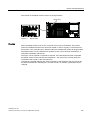
General layout of SINAMICS G110D...........................................................................................38
4.3
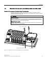
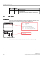
Removal of CU area cover and braking resistor connection hatch .............................................39
4.4
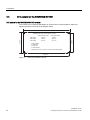
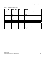
Drill pattern for the SINAMICS G110D ........................................................................................40
4.5
Mounting orientation ....................................................................................................................41
4.6
Ambient operating conditions.......................................................................................................42
4.7
SINAMICS G110D Specifications ................................................................................................43
4.8
Cables and connections...............................................................................................................44
4.9
Configuring the AS-i slave ...........................................................................................................50
4.10
Using the AS-i Programmer .........................................................................................................55
Commissioning ........................................................................................................................................ 59
5.1
Typical commissioning scenarios ................................................................................................59
5.2
Restoring the factory settings ......................................................................................................60
5.3
Preparing for commissioning .......................................................................................................61
5.4
Prerequisites of using the factory settings ...................................................................................64
5.5
Factory settings for the Inverter ...................................................................................................64
5.6
Commissioning with STARTER ...................................................................................................66
5.7
Commissioning with the IOP........................................................................................................76
SINAMICS G110D
Operating Instructions, 2010-20-06, A5E02385577A2 AB
5
Table of contents
6
6
5.8
Example application .................................................................................................................... 81
5.9
5.9.1
5.9.2
Backup data and storage ............................................................................................................ 85
Saving and transferring data using the IOP ................................................................................ 85
Saving and transferring data using the MMC.............................................................................. 86
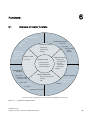
Functions ................................................................................................................................................. 89
6.1
Overview of Inverter functions..................................................................................................... 89
6.2
6.2.1
6.2.2
6.2.3
6.2.4
6.2.5
6.2.6
Inverter Control ........................................................................................................................... 91
Frequency inverter control using digital inputs (two/three-wire control) ..................................... 91
Two-wire control, method 1......................................................................................................... 94
Two-wire control, method 2......................................................................................................... 95
Two-wire control, method 3......................................................................................................... 96
Three-wire control, method 1 ...................................................................................................... 97
Three-wire control, method 2 ...................................................................................................... 99
6.3
6.3.1
6.3.2
6.3.3
Command sources .................................................................................................................... 100
Selecting command sources ..................................................................................................... 100
Assigning functions to digital inputs .......................................................................................... 101
Controlling the motor using the fieldbus.................................................................................... 102
6.4
6.4.1
6.4.2
6.4.3
6.4.4
6.4.5
6.4.6
Setpoint sources ....................................................................................................................... 102
Selecting the setpoint source [P1000] ...................................................................................... 102
Frequency setpoint using analog input [P1000=2].................................................................... 103
Using a motorized potentiometer as a setpoint source............................................................. 103
Using fixed frequencies as a setpoint source ........................................................................... 104
Running the motor in jog mode (JOG function) ........................................................................ 105
Specifying the motor speed via the fieldbus ............................................................................. 106
6.5
Changing over the command data sets (manual, automatic) ................................................... 107
6.6
6.6.1
6.6.2
6.6.3
Setpoint preparation.................................................................................................................. 109
Overview of setpoint preparation .............................................................................................. 109
Minimum frequency and maximum frequency .......................................................................... 109
Parameterizing the ramp-function generator ............................................................................ 110
6.7
6.7.1
6.7.2
6.7.3
6.7.4
Motor control ............................................................................................................................. 111
V/f control with linear characteristics......................................................................................... 111
V/f control with parabolic characteristic..................................................................................... 113
Typical applications for V/f control ............................................................................................ 113
Additional characteristics of the V/f control ............................................................................... 113
6.8
6.8.1
6.8.2
6.8.3
6.8.4
6.8.5
Protection functions................................................................................................................... 114
Protective functions of the frequency inverter........................................................................... 114
Overtemperature protection for the Inverter.............................................................................. 115
Overcurrent protection .............................................................................................................. 117
Limiting the maximum DC link voltage...................................................................................... 119
Load torque monitoring (system protection) ............................................................................. 120
6.9
6.9.1
6.9.2
6.9.2.1
6.9.2.2
6.9.2.3
6.9.2.4
6.9.3
6.9.3.1
6.9.3.2
Technological functions............................................................................................................. 121
Technological functions............................................................................................................. 121
Braking functions....................................................................................................................... 122
Braking functions of the Inverter ............................................................................................... 122
DC braking ................................................................................................................................ 123
Dynamic braking ....................................................................................................................... 125
Parameterizing a motor holding brake ...................................................................................... 127
Automatic restart and flying restart ........................................................................................... 131
Automatic restart ....................................................................................................................... 131
Flying restart ............................................................................................................................. 135
SINAMICS G110D
Operating Instructions, 2010-20-06, A5E02385577A2 AB
Table of contents
7
8
9
A
6.9.4
6.9.5
6.9.6
PID technology controller...........................................................................................................137
Logical functions using function blocks......................................................................................138
Changing over drive data sets ...................................................................................................139
6.10
Quick Stop function....................................................................................................................141
6.11
6.11.1
6.11.1.1
6.11.1.2
6.11.1.3
6.11.1.4
6.11.1.5
6.11.1.6
Operation in fieldbus systems....................................................................................................145
Communication via AS-i Network ..............................................................................................145
Overview ....................................................................................................................................145
Connecting the Inverter to AS-i network ....................................................................................147
Example: configuring the Inverter on the AS-i network .............................................................148
AS-i Profile .................................................................................................................................155
Step 7 example conveyor program............................................................................................172
Example application...................................................................................................................178
Service and maintenance ...................................................................................................................... 183
7.1
Behaviour of the Inverter when replacing components .............................................................183
7.2
Replacing the Inverter................................................................................................................184
7.3
Local/remote switch cover .........................................................................................................185
7.4
Repair switch..............................................................................................................................186
Messages and fault codes ..................................................................................................................... 189
8.1
Fault codes.................................................................................................................................189
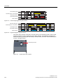
8.2
LED States .................................................................................................................................190
Technical data ....................................................................................................................................... 193
9.1
Technical data of the SINAMICS G110D...................................................................................193
9.2
Pulse frequency and current reduction ......................................................................................195
Appendix A ............................................................................................................................................ 197
A.1
A.1.1
A.1.2
Electromagnetic compatibility ....................................................................................................197
Classification of EMC categories ...............................................................................................197
EMC performance......................................................................................................................199
A.2
Standards...................................................................................................................................201
Index...................................................................................................................................................... 203
SINAMICS G110D
Operating Instructions, 2010-20-06, A5E02385577A2 AB
7
Table of contents
Tables
Table 2- 1
This is how you filter the parameter list to keep the number of displayed parameters to a
minimum.......................................................................................................................................24
Table 2- 2
How to switch to commissioning mode or restore the factory setting ..........................................24
Table 2- 3
How to determine the firmware version of the Control Unit .........................................................24
Table 2- 4
This is how you reset the parameters to the factory setting ........................................................24
Table 2- 5
This is how you select the command source of the control signals (ON/OFF, reversing) of
the inverter ...................................................................................................................................24
Table 2- 6
This is how you select the setpoint source for the frequency ......................................................25
Table 2- 7
This is how you parameterize the up and down ramps ...............................................................25
Table 2- 8
This is how you optimize the starting behavior of the V/f control for a high break loose
torque and overload .....................................................................................................................25
Table 2- 9
Binector symbols..........................................................................................................................27
Table 2- 10
Connector symbols ......................................................................................................................27
Table 2- 11
Connector and binector output symbols ......................................................................................28
Table 2- 12
Parameterizing an interlock..........................................................................................................29
Table 3- 1
SINAMICS G110D Braking resistors ...........................................................................................36
Table 4- 1
Rated Output, Input and Fuses....................................................................................................43
Table 4- 2
Tools.............................................................................................................................................47
Table 4- 3
Control Unit connectors................................................................................................................47
Table 4- 4
Mains supply connector ...............................................................................................................47
Table 4- 5
Motor connector ...........................................................................................................................48
Table 4- 6
Temperature sensor and EM brake .............................................................................................48
Table 4- 7
Mains supply and motor output specifications .............................................................................48
Table 4- 8
Digital input specifications............................................................................................................49
Table 4- 9
Analog input specifications...........................................................................................................49
Table 4- 10
AS-i connector specifications .......................................................................................................49
Table 4- 11
Equipment for installation of SINAMICS G110D (AS-i) ...............................................................51
Table 5- 1
Command and setpoint sources ..................................................................................................64
Table 5- 2
Factory setting of additional important parameters......................................................................65
Table 5- 3
Function of the IOP controls.........................................................................................................78
Table 5- 4
Handheld device order information ..............................................................................................79
Table 5- 5
Conveyor application parameters ................................................................................................83
Table 6- 1
Comparison of the methods for two-wire motor control ...............................................................92
Table 6- 2
Comparison of the methods for three-wire motor control ............................................................93
Table 6- 3
Function table...............................................................................................................................95
8
SINAMICS G110D
Operating Instructions, 2010-20-06, A5E02385577A2 AB
Table of contents
Table 6- 4
Parameterizing the function .........................................................................................................95
Table 6- 5
Function table...............................................................................................................................96
Table 6- 6
Parameterizing the function .........................................................................................................96
Table 6- 7
Function table...............................................................................................................................97
Table 6- 8
Parameterizing the function .........................................................................................................97
Table 6- 9
Function table...............................................................................................................................98
Table 6- 10
Parameterizing the function .........................................................................................................98
Table 6- 11
Function table...............................................................................................................................99
Table 6- 12
Parameterizing the function .......................................................................................................100
Table 6- 13
Parameters, to select the source for the inverter control commands ........................................100
Table 6- 14
Factory setting of the digital inputs ............................................................................................101
Table 6- 15
Changing the digital input settings .............................................................................................101
Table 6- 16
Settings to select the possible frequency setpoint sources .......................................................102
Table 6- 17
Set and parameterize the analog input for use as setpoint source ...........................................103
Table 6- 18
Example: Implementing the motorized potentiometer using the Operator Panel keys..............103
Table 6- 19
Example: Implementing a motorized potentiometer using digital inputs ...................................104
Table 6- 20
Parameters to directly select frequencies..................................................................................105
Table 6- 21
Example: Selecting 2 fixed frequencies using digital input 2 and digital input 3 .......................105
Table 6- 22
Example: Enabling the jog mode ...............................................................................................106
Table 6- 23
Parameter to assign the JOG function to another button ..........................................................106
Table 6- 24
Command data set changeover using parameters P0810 and P0811......................................108
Table 6- 25
Parameters for switching the command data sets:....................................................................108
Table 6- 26
Parameters for minimum and maximum frequency ...................................................................110
Table 6- 27
Parameters for ramp-up time and ramp-down time ...................................................................110
Table 6- 28
Rounding parameters ................................................................................................................111
Table 6- 29
Setting the control type ..............................................................................................................111
Table 6- 30
Optimizing the starting characteristics for a linear characteristic...............................................112
Table 6- 31
Setting the control type ..............................................................................................................113
Table 6- 32
Further V/f control methods (P1300) .........................................................................................114
Table 6- 33
Parameters to sense the temperature using a temperature sensor ..........................................117
Table 6- 34
Imax controller parameters...........................................................................................................118
Table 6- 35
VDCmax controller parameters......................................................................................................119
Table 6- 36
Parameterizing the monitoring functions ...................................................................................120
Table 6- 37
Braking methods depending on the application.........................................................................122
Table 6- 38
Parameters to enable and set DC braking.................................................................................124
Table 6- 39
Parameters to enable and set dynamic braking ........................................................................127
SINAMICS G110D
Operating Instructions, 2010-20-06, A5E02385577A2 AB
9
Table of contents
Table 6- 40
Control logic parameters of the motor holding brake.................................................................130
Table 6- 41
Parameter to force open a motor holding brake ........................................................................131
Table 6- 42
Parameterizing the automatic restart .........................................................................................133
Table 6- 43
Principle of operation of the automatic restart ...........................................................................133
Table 6- 44
Overview of the automatic restart characteristics ......................................................................135
Table 6- 45
Main function parameters...........................................................................................................136
Table 6- 46
Overview: the "flying restart" function ........................................................................................136
Table 6- 47
Additional commissioning parameters .......................................................................................137
Table 6- 48
Technology controller parameters .............................................................................................138
Table 6- 49
Parameters for using the free function blocks............................................................................139
Table 6- 50
Parameters for switching the drive data sets: ............................................................................141
Table 6- 51
Quick Stop parameters ..............................................................................................................143
Table 6- 52
ASI connector specifications ......................................................................................................147
Table 6- 53
AS-i single slave identities .........................................................................................................155
Table 6- 54
Selection of slave mode (P2022) ...............................................................................................155
Table 6- 55
AS-i dual slave identities ............................................................................................................157
Table 6- 56
Summary of parameter P2021 settings .....................................................................................159
Table 6- 57
ID1 Code modification (P2023)..................................................................................................159
Table 6- 58
Default input process image (slave to master) - Dual slave mode ............................................160
Table 6- 59
Default output process image (master to slave) - Dual slave mode ..........................................161
Table 6- 60
Default input process image (slave to master) - Single slave mode..........................................161
Table 6- 61
Default output process image (master to slave) - Single slave mode .......................................162
Table 6- 62
Request IDs from master to slave..............................................................................................163
Table 6- 63
Response IDs from slave to master...........................................................................................163
Table 6- 64
PKW error codes........................................................................................................................164
Table 6- 65
IND parameter index ..................................................................................................................165
Table 6- 66
CCT2 commands .......................................................................................................................166
Table 6- 67
Standard error codes .................................................................................................................167
Table 6- 68
Conveyor application parameters ..............................................................................................180
Table 7- 1
Switch cover function description...............................................................................................186
Table 8- 1
Fault codes description ..............................................................................................................189
Table 8- 2
SINAMICS G110D LED states...................................................................................................191
Table 9- 1
Weight of SINAMICS G110 Inverters with repair switch............................................................194
Table 9- 2
Weight of SINAMICS G110 Inverters without repair switch.......................................................194
Table 9- 3
Current reduction depending on pulse frequency......................................................................195
Table A- 1
Compliance Table ......................................................................................................................199
10
SINAMICS G110D
Operating Instructions, 2010-20-06, A5E02385577A2 AB
Table of contents
Table A- 2
Conducted & Radiated Emissions .............................................................................................199
Table A- 3
Harmonic Currents.....................................................................................................................200
Table A- 4
EMC Immunity............................................................................................................................200
SINAMICS G110D
Operating Instructions, 2010-20-06, A5E02385577A2 AB
11
Table of contents
Figures
Figure 2-1
Example: Pre-assigned signal interconnection for digital input 0 of a non-bus-capable
Control Unit ..................................................................................................................................26
Figure 2-2
Example: MOP function (motorized potentiometer).....................................................................26
Figure 2-3
Example: Signal interconnection for interlock ..............................................................................29
Figure 2-4
Default parameterization ..............................................................................................................29
Figure 2-5
BICO parameterization.................................................................................................................29
Figure 2-6
Interconnection after insertion of two functions............................................................................29
Figure 3-1
SINAMICS G110D FSA ...............................................................................................................32
Figure 3-2
SINAMICS G110D FSB ...............................................................................................................33
Figure 3-3
SINAMICS G110D FSC ...............................................................................................................33
Figure 4-1
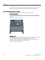
SINAMICS G110D Inverter ..........................................................................................................38
Figure 4-2
Removal of CU area cover and braking resistor connection hatch..............................................39
Figure 4-3
Drill pattern SINAMICS G110D....................................................................................................40
Figure 4-4
Correct Inverter orientation ..........................................................................................................41
Figure 4-5
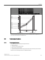
Power derating for temperature ...................................................................................................42
Figure 4-6
Derating for altitiude .....................................................................................................................42
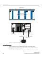
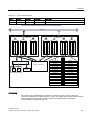
Figure 4-7
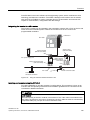
SINAMICS G110D block diagram................................................................................................46
Figure 4-8
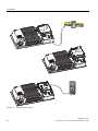
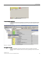
Example AS-i configuration..........................................................................................................52
Figure 4-9
Addressing the ASi slave .............................................................................................................54
Figure 5-1
Communications interfaces..........................................................................................................60
Figure 5-2
Rating plate data as parameters..................................................................................................62
Figure 5-3
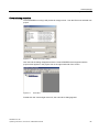
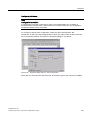
Create new project dialog ............................................................................................................67
Figure 5-4
Insert drive....................................................................................................................................67
Figure 5-5
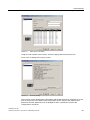
Select drive dialog........................................................................................................................68
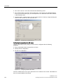
Figure 5-6
Configure drive unit ......................................................................................................................68
Figure 5-7
Select power unit dialog ...............................................................................................................69
Figure 5-8
Summary dialog ...........................................................................................................................69
Figure 5-9
Select control method dialog........................................................................................................70
Figure 5-10
Select command and setpoint source dialog ...............................................................................70
Figure 5-11
Select drive settings dialog ..........................................................................................................71
Figure 5-12
Select motor type dialog...............................................................................................................71
Figure 5-13
Motor data dialog .........................................................................................................................72
Figure 5-14
Motor identification dialog ............................................................................................................72
Figure 5-15
Important parameters dialog ........................................................................................................73
Figure 5-16
Calculate motor data dialog .........................................................................................................73
12
SINAMICS G110D
Operating Instructions, 2010-20-06, A5E02385577A2 AB
Table of contents
Figure 5-17
Configuration summary................................................................................................................74
Figure 5-18
Control panel activation ...............................................................................................................74
Figure 5-19
STARTER control panel...............................................................................................................75
Figure 5-20
Expert list .....................................................................................................................................75
Figure 5-21
Layout of IOP ...............................................................................................................................77
Figure 5-22
IOP Handheld Kit .........................................................................................................................79
Figure 5-23
Example conveyor application .....................................................................................................82
Figure 5-24
Example S7 script ........................................................................................................................83
Figure 5-25
Example S7 ladder logic ..............................................................................................................84
Figure 6-1
Overview of Inverter functions .....................................................................................................89
Figure 6-2
Two-wire control using digital inputs, method 1...........................................................................94
Figure 6-3
Two-wire control using digital inputs, method 2...........................................................................95
Figure 6-4
Two-wire control using digital inputs, method 3...........................................................................96
Figure 6-5
Three-wire control using digital inputs, method 1 ........................................................................97
Figure 6-6
Three-wire control using digital inputs, method 2 ........................................................................99
Figure 6-7
CDS switchover in the inverter...................................................................................................107
Figure 6-8
Setpoint calculation in the inverter .............................................................................................109
Figure 6-9
DC braking after an OFF1 or OFF3 command ..........................................................................123
Figure 6-10
DC braking using external selection ..........................................................................................125
Figure 6-11
Braking chopper in the Inverter..................................................................................................126
Figure 6-12
Function diagram of the motor holding brake control after an OFF1 or OFF3 command .........128
Figure 6-13
Function diagram, motor holding brake after an OFF2 command.............................................129
Figure 6-14
Example: technology controller as a level controller..................................................................138
Figure 6-15
Drive Data Sets switchover in Inverter.......................................................................................140
Figure 6-16
Conveyor example 1 ..................................................................................................................142
Figure 6-17
Conveyor example 2 ..................................................................................................................142
Figure 6-18
Conveyor example 3 ..................................................................................................................142
Figure 6-19
Positive edge triggered signals reactions ..................................................................................144
Figure 6-20
High level triggered signals reactions ........................................................................................144
Figure 6-21
Keypad Quick Stop override ......................................................................................................144
Figure 6-22
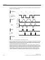
AS-i network structure................................................................................................................145
Figure 6-23
AS-i communications using Manchester coding ........................................................................146
Figure 6-24
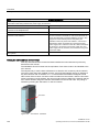
Using the CP343-2 Master with the S7-300 ..............................................................................149
Figure 6-25
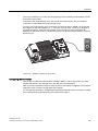
AS-i master - set button .............................................................................................................150
Figure 6-26
Setting the address on the Inverter............................................................................................151
Figure 6-27
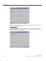
Properties dialog CP343-2 - addresses.....................................................................................152
SINAMICS G110D
Operating Instructions, 2010-20-06, A5E02385577A2 AB
13
Table of contents
Figure 6-28
Properties dialog CP343-2 - operating parameters ...................................................................152
Figure 6-29
Properties dialog CP343-2 - slave configuration .......................................................................153
Figure 6-30
Configuring an individual slave ..................................................................................................154
Figure 6-31
Configuring standard AS-i slave ................................................................................................154
Figure 6-32
Single Slave Internal data flow...................................................................................................156
Figure 6-33
Dual slave internal data flow ......................................................................................................157
Figure 6-34
PKW component structure .........................................................................................................162
Figure 6-35
PKE component structure ..........................................................................................................163
Figure 6-36
IND component structure ...........................................................................................................165
Figure 6-37
PWE component structure .........................................................................................................166
Figure 6-38
Cyclic data transfer ....................................................................................................................167
Figure 6-39
Cyclic data output.......................................................................................................................167
Figure 6-40
Cyclic data input.........................................................................................................................168
Figure 6-41
Standard ID read request and response....................................................................................168
Figure 6-42
Standard diagnostic request and response ...............................................................................168
Figure 6-43
Unrecognised standard acyclic request and response ..............................................................168
Figure 6-44
Parameter read request and response ......................................................................................170
Figure 6-45
Parameter write request and response......................................................................................171
Figure 6-46
Parameter exchange request and response..............................................................................172
Figure 6-47
Example conveyor application script - main program ................................................................173
Figure 6-48
Example conveyor application script - control of several conveyor belts ..................................175
Figure 6-49
Example conveyor application script - controlling a conveyor belt ............................................175
Figure 6-50
Example conveyor script - control a conveyor belt without block parameters ...........................176
Figure 6-51
Example conveyor application script - parts counter with monitor.............................................177
Figure 6-52
Example conveyor script - parts counter and monitoring without block parameters .................178
Figure 6-53
Example conveyor application ...................................................................................................179
Figure 6-54
Example S7 script ......................................................................................................................180
Figure 6-55
Example S7 ladder logic ............................................................................................................181
Figure 7-1
Local/remote switch cover layout...............................................................................................185
Figure 7-2
Repair switch..............................................................................................................................187
Figure 8-1
SINAMICS G110D LEDs............................................................................................................190
14
SINAMICS G110D
Operating Instructions, 2010-20-06, A5E02385577A2 AB
Warnings and cautions
1.1
1
Warning and Cautions
General
WARNING
This equipment contains dangerous voltages and controls potentially dangerous rotating
mechanical parts. Non-compliance with the warnings or failure to follow the instructions
contained in this manual can result in loss of life, severe personal injury or serious damage
to property.
Protection in case of direct contact by means of SELV / PELV is only permissible in areas
with equipotential bonding and in dry indoor rooms. If these conditions are not fulfilled,
other protective measures against electric shock must be applied e.g. protective insulation.
Only suitably qualified personnel should work on this equipment, and only after becoming
familiar with all safety notices, installation, operation and maintenance procedures
contained in this manual. The successful and safe operation of this equipment is dependent
upon its proper handling, installation, operation and maintenance.
As the earth leakage for this product can be greater than 3.5 mA a.c., a fixed earth
connection is required and the minimum size of the protective earth conductor shall comply
with the local safety regulations for high leakage current equipment. In this case a
permanent, immovable connection is required and the following measures must also be
taken:
Minimum PE conductor cross-section of 10 mm2.
Laying a second PE conductor using separate terminals, with a cross-section that, in
itself, fulfills all the requirements for PE conductors.
Self-actuating switch-off of the power supply if the PE conductor is interrupted.
Insertion of a two-winding transformer into the power supply.
Due to the high inrush currents in the earth conductor, this product is not compatible with
an RCD (also referred to as an ELCB or RCCB).
The power supply, DC and motor terminals, the brake and thermistor cables can carry
dangerous voltages even if the inverter is inoperative. Wait at least five minutes to allow the
unit to discharge after switching off the line supply before carrying out any installation work.
It is strictly prohibited for any mains disconnection to be performed on the motor-side of the
system; any disconnection of the mains must be performed on the mains-side of the
Inverter.
When connecting the line supply to the Inverter, make sure that the terminal case of the
motor is closed.
SINAMICS G110D
Operating Instructions, 2010-20-06, A5E02385577A2 AB
15
Warnings and cautions
1.1 Warning and Cautions
During operation and for a short time after switching-off the Inverter, the surfaces of the
Inverter can reach a high temperature.
This equipment is capable of providing internal motor overload protection according to
UL508C. Refer to P0610 and P0335, i²t is ON by default.
When changing from the ON to OFF-state of an operation if an LED or other similar display
is not lit or active; this does not indicate that the unit is switched-off or powered-down.
The inverter must always be grounded.
Isolate the line supply before making or changing connections to the unit.
Use of mobile radio devices (e.g. telephones, walkie-talkies) with a transmission power > 1
W in the immediate vicinity of the devices (< 1.8 m) can interfere with the functioning of the
equipment.
Do not disconnect power connections when the Inverter and motor are under load.
Ensure that the inverter is configured for the correct supply voltage. The inverter must not
be connected to a higher voltage supply.
Static discharges on surfaces or interfaces that are not generally accessible (e.g. terminal
or connector pins) can cause malfunctions or defects. Therefore, when working with
inverters or inverter components, ESD protective measures should be observed.
Take particular notice of the general and regional installation and safety regulations
regarding work on dangerous voltage installations (e.g. EN 50178) as well as the relevant
regulations regarding the correct use of tools and personal protective equipment (PPE).
CAUTION
Children and the general public must be prevented from accessing or approaching the
equipment!
This equipment may only be used for the purpose specified by the manufacturer.
Unauthorized modifications and the use of spare parts and accessories that are not sold or
recommended by the manufacturer of the equipment can cause fires, electric shocks and
injuries.
NOTICE
Keep this manual within easy reach of the equipment and make it available to all users.
Whenever measuring or testing has to be performed on live equipment, the regulations of
Safety Code BGV A2 must be observed, in particular § 8 "Permissible Deviations when
Working on Live Parts". Suitable electronic tools should be used.
Before installing and commissioning, please read these safety instructions and warnings
carefully and all the warning labels attached to the equipment. Make sure that the warning
labels are kept in a legible condition and replace missing or damaged labels.
16
SINAMICS G110D
Operating Instructions, 2010-20-06, A5E02385577A2 AB
Warnings and cautions
1.1 Warning and Cautions
Transport and storage
WARNING
Correct transport, storage as well as careful operation and maintenance are essential for
the proper and safe operation of the equipment.
CAUTION
Protect the equipment against physical shocks and vibration during transport and storage. It
is important that the equipment is protected from water (rainfall) and excessive
temperatures.
Commissioning
WARNING
Working on the equipment by unqualified personnel or failure to comply with warnings can
result in severe personal injury or serious damage to material. Only suitably qualified
personnel trained in the setup, installation, commissioning and operation of the product
should carry out work on the equipment.
CAUTION
Cable connection
The control cables must be laid separately from the power cables. Carry out the
connections as shown in the installation section in this manual, to prevent inductive and
capacitive interference from affecting the correct function of the system.
SINAMICS G110D
Operating Instructions, 2010-20-06, A5E02385577A2 AB
17
Warnings and cautions
1.1 Warning and Cautions
Operation
WARNING
The Inverter operate at high voltages.
When operating electrical devices, it is impossible to avoid applying hazardous voltages to
certain parts of the equipment.
Emergency Stop facilities according to EN 60204, IEC 204 (VDE 0113) must remain
operative in all operating modes of the control equipment. Any disengagement of the
Emergency Stop facility must not lead to an uncontrolled or an undefined restart of the
equipment.
Certain parameter settings may cause the Inverter to restart automatically after an input
power failure, for example, the automatic restart function.
Wherever faults occurring in the control equipment can lead to substantial material damage
or even grievous bodily injury (that is, potentially dangerous faults), additional external
precautions must be taken or facilities provided to ensure or enforce safe operation, even
when a fault occurs (e.g. independent limit switches, mechanical interlocks, etc.).
Motor parameters must be accurately configured for motor overload protection to operate
correctly.
This equipment is capable of providing internal motor overload protection according to
UL508C.
Only Inverters with fail-safe functions can be used as an "Emergency Stop Mechanism"
(see EN 60204, section 9.2.5.4).
Repair
WARNING
Repairs on equipment may only be carried out by Siemens Service, by repair centers
authorized by Siemens or by authorized personnel who are thoroughly acquainted with all
the warnings and operating procedures contained in this manual.
Any defective parts or components must be replaced using parts contained in the relevant
spare parts list.
Disconnect the power supply before opening the equipment for access.
Dismantling and disposal
CAUTION
The packaging of the Inverter is re-usable. Retain the packaging for future use.
Easy-to-release screw and snap connectors allow you to break the unit down into its
component parts. You can recycle these component parts, dispose of them in accordance
with local requirements or return them to the manufacturer.
18
SINAMICS G110D
Operating Instructions, 2010-20-06, A5E02385577A2 AB
Warnings and cautions
1.1 Warning and Cautions
SINAMICS G110D
Operating Instructions, 2010-20-06, A5E02385577A2 AB
19
Warnings and cautions
1.1 Warning and Cautions
20
SINAMICS G110D
Operating Instructions, 2010-20-06, A5E02385577A2 AB
2
Introduction
2.1
About this manual
Who requires the operating instructions and why?
These operating instructions primarily address fitters, commissioning engineers and machine
operators. The operating instructions describe the devices and device components and
enable the target groups being addressed to install, connect-up, parameterize, and
commission the inverters safely and in the correct manner.
What is described in the operating instructions?
These operating instructions provide a summary of all of the information required to operate
the inverter under normal, safe conditions.
The information provided in the operating instructions has been compiled in such a way that
it is sufficient for all standard applications and enables drives to be commissioned as
efficiently as possible. Where it appears useful, additional information for entry level
personnel has been added.
The operating instructions also contain information about special applications. Since it is
assumed that readers already have a sound technical knowledge of how to configure and
parameterize these applications, the relevant information is summarized accordingly. This
relates, e.g. to operation with fieldbus systems and safety-related applications.
Additional information on SINAMICS G110D
● As download: List Manual SINAMICS G110D
Among other things, the List manual includes
– A detailed description of all of the parameters
– Function diagrams of all of the inverter functions
– A list of the fault messages and alarms
● As download: All of the operating instructions, manuals on SINAMICS G110D
http://support.automation.siemens.com/WW/view/de/22339653/133300
● On DVD: SD Manual Collection - all manuals on low-voltage motors, geared motors and
low-voltage inverters, 5 languages.
– MLFB: 6SL3298-0CA00-0MG0 (supplied once)
– MLFB: 6SL3298-0CA10-0MG0 (update service for 1 year; supplied 4 times)
● As download: Catalog D 11.1: SINAMICS G110 / G120 Inverter Chassis Units SINAMICS
G120D and SINAMICS G110D Distributed Inverters.
http://sd.nes.siemens.de/sales_2003/support/info/catalogues/html_00/index.html#Catalog
s_Inverters
The catalog includes ordering data as well as engineering and selection data.
SINAMICS G110D
Operating Instructions, 2010-20-06, A5E02385577A2 AB
21
Introduction
2.2 Adapting the Inverter to the application
2.2
Adapting the Inverter to the application
2.2.1
General basics
Parameterizable inverters transform standard motors into variable-speed drives
Inverters are parameterized to adapt them to the motor being driven so that this can be
optimally operated and protected. This is realized using one of the following operator units:
● Intelligent Operator Panel (IOP) hand-held kit.
● Software (STARTER commissioning tool) that allows the inverter to be parameterized
and controlled from a PC.
Inverters are used to improve and expand the starting and speed response of motors.
Many standard applications can function with the default parameters
Although inverters can be parameterized for very specific applications, many standard
applications can be configured by means of just a few parameters.
Use the factory settings (where possible)
For basic applications, commissioning can be carried out using just the factory settings.
Use quick commissioning (for simple, standard applications)
In the majority of standard applications, commissioning can be carried out by entering or
changing just a few parameters during quick commissioning.
2.2.2
Parameter
Parameter types
There are two types of parameters, adjustable and display parameters.
Adjustable parameters
Adjustable parameters are represented with four digits preceded by the letter "P". You can
change the value of these parameters within a defined range.
Example:
P0305 is the parameter for the rated motor current in Amps. This parameter is set during
commissioning. You can enter values between 0.01 and 10000.
Display parameters
Display parameters are represented with four digits preceded by the letter "r". You cannot
change the value of these parameters.
22
SINAMICS G110D
Operating Instructions, 2010-20-06, A5E02385577A2 AB
Introduction
2.2 Adapting the Inverter to the application
Example:
r0027 is the parameter for the inverter output current. The inverter measures the current and
writes the current value to the parameter. You can display the parameter value, e.g. using an
analog output of the inverter.
Change protection for setting parameters
The process of changing parameter values is subject to certain conditions. If an attempt to
change a parameter is rejected by the inverter, this can have a number of causes:
1. The inverter operating state does not allow you to change parameters.
For example, certain parameters can only be changed when the inverter is in
commissioning mode.
2. In some cases, you may not be able to change certain parameters due to automatic
follow-on parameterization.
Example: When P0701 = 1, the ON/OFF1 command is connected to digital input 0. As
follow-on parameterization, P0840 (source of the ON/OFF1 command) is assigned value
722.0 (status of digital input 0). which means that P0840 can no longer be changed.
3. Parameter protection via P0927 has been activated.
Example: P0927 = 1101 prevents parameters from being changed from the BOP.
For each parameter, the List Manual specifies whether and which conditions apply for
changing the values.
2.2.3
Parameters with follow-on parameterization
When you change certain parameters, the system may automatically change other
parameters accordingly. This makes it much easier to parameterize complex functions.
Example: Parameter P0700 (command source)
Parameter P0700 can be used to switch the command source from the fieldbus to digital
inputs. When the value of P0700 is changed from 6 (command source "fieldbus") to 2
(command source "digital inputs"), other parameter values are changed automatically:
● New functions are assigned to the digital inputs (P0701 ... P0704)
● Inverter control is interconnected with the signals from the digital inputs (P0800, P0801,
P0840, etc.)
For more information about follow-on parameterization for P0700, see the List Manual.
SINAMICS G110D
Operating Instructions, 2010-20-06, A5E02385577A2 AB
23
Introduction
2.2 Adapting the Inverter to the application
2.2.4
Frequently required parameters
Parameters that in many cases help
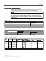
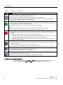
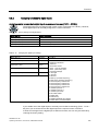
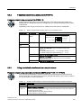
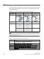
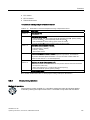
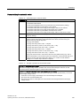
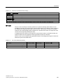
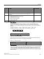
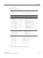
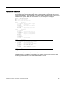
Table 2- 1
This is how you filter the parameter list to keep the number of displayed parameters to a minimum
Parameter
Description
P0003 =
User access level
1: Standard: Allows access to the most frequently used parameters (factory setting)
2: Extended: Extended access, e.g. to inverter I/O functions
3: Expert: To be used by experts
P0004 =
Parameter filter
0: All the parameters are displayed (factory setting).
2: Inverter
3: Motor - data of the motor and output filter are displayed
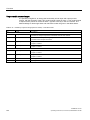
Table 2- 2
How to switch to commissioning mode or restore the factory setting
Parameter
Description
P0010 =
Commissioning parameters
0: Ready (factory setting)
1: Perform quick commissioning
30: Factory setting - initiate restore factory settings
Table 2- 3
How to determine the firmware version of the Control Unit
Parameter
Description
r0018
The firmware version is displayed:
Table 2- 4
This is how you reset the parameters to the factory setting
Parameter
Description
P0010 = 30
30: Factory setting - initiate restore factory settings
P0970 = 1
1: Resetting - restoring all parameters to the factory setting
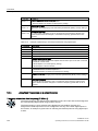
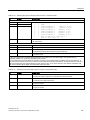
Table 2- 5
This is how you select the command source of the control signals (ON/OFF, reversing) of the inverter
Parameter
Description
P0700 =
0: Factory default setting
2: Digital inputs
4: USS on RS 232
6: Fieldbus ; default setting
24
SINAMICS G110D
Operating Instructions, 2010-20-06, A5E02385577A2 AB
Introduction
2.2 Adapting the Inverter to the application
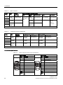
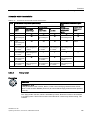
Table 2- 6
This is how you select the setpoint source for the frequency
Parameters
Description
P1000 =
0: No main setpoint
1: MOP setpoint
3: Fixed frequency (factory default setting)
4: USS at RS 232
6: Fieldbus
Table 2- 7
This is how you parameterize the up and down ramps
Parameters
Description
P1080 = …
Minimum frequency
0.00 [Hz] factory setting
P1082 = …
Maximum frequency
50.00 [Hz] factory setting
P1120 = …
Ramp-up time
10.00 [s]
P1121 = …
Ramp-down time
10.00 [s]
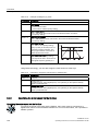
Table 2- 8
This is how you optimize the starting behavior of the V/f control for a high break loose torque and overload
Parameters
Description
P0003 = 2
Extended access
P1310 = …
Voltage boost to compensate resistive losses
The voltage boost is effective from standstill up to the rated speed.
The voltage boost continually decreases with increasing speed.
The maximum voltage boost is effective at speed zero and is in V:
V_ConBoost, 100 = sqrt(3) * P0305 * P0350 * (P1310/100)
P1311 = …
Voltage when accelerating
The voltage boost is effective from standstill up to the rated speed.
The voltage boost is independent of the speed.
The voltage boost in V is:
V_AccBoost,100 = sqrt(3) * P0305 * P0350 * (P1311/100)
SINAMICS G110D
Operating Instructions, 2010-20-06, A5E02385577A2 AB
25
Introduction
2.3 Extended adaptation of parameters
2.3
Extended adaptation of parameters
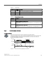
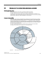
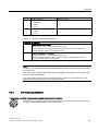
2.3.1
BICO technology: basic principles
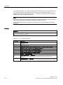
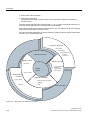
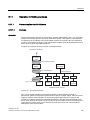
Functional principle of BICO technology and inverter open-loop control functions
The inverter software offers a range of open-loop control functions, communication functions,
as well as various diagnostics and operating functions. These functions are interconnected
via internal signal paths and represent the default control structure.
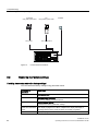
3
',
21
2))
U
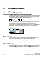
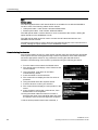
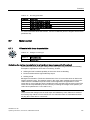
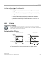
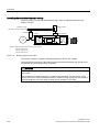
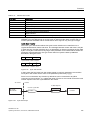
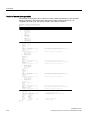
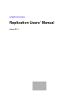
Figure 2-1
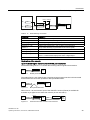
Example: Pre-assigned signal interconnection for digital input 0 of a non-bus-capable
Control Unit
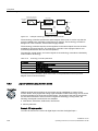
The functions can be parameterized and interconnected as required. The signal
interconnection of the functions is realized, contrary to electric circuitry, not using cables, but
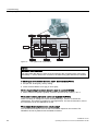
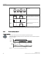
in the software. The various functions use a range of inputs, outputs, and parameters.
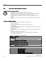
Inputs
Parameter
Output
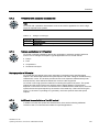
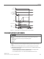
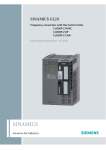
MOP
MOP output
speed
[rpm]
r1050
MOP enable (higher)
p1035
MOP enable (lower)
p1036
Figure 2-2
Example: MOP function (motorized potentiometer)
Binectors and connectors
Connectors and binectors are elements used to exchange signals between the individual
functions. Connectors and binectors can be seen as "storage compartments":
● Connectors are used to store "analog" signals (e.g. speed setpoint)
● Binectors are used to store "digital" signals (e.g. 'MOP raise' command)
Definition of BICO technology
BICO technology describes the type of parameterization that can be used to disconnect all
the internal signal interconnections between the functions or establish new connections. This
is realized using Binectors and Connectors. Hence the name BICO technology. ( Binector
Connector Technology)
26
SINAMICS G110D
Operating Instructions, 2010-20-06, A5E02385577A2 AB
Introduction
2.3 Extended adaptation of parameters
BICO parameters
You can use the BICO parameters to define the sources of the input signals of a function.
This means that using BICO parameters you can define from which connectors and
binectors a function reads-in its input signals, thereby enabling you to "interconnect" the
functions stored in the devices in accordance with your requirements. Five different BICO
parameter types are available:
● Binector inputs: BI
● Connector inputs: CI
● Binector outputs: BO
● Connector outputs: CO
● Binector/connector outputs: CO/BO
Binector/connector outputs (CO/BO) are parameters that combine more than one binector
output in a single word (e.g. r0052 CO/BO: status word 1). Each bit in the word represents a
digital (binary) signal. This feature reduces the number of parameters and makes it easier to
set parameters by means of the serial interface (data transfer).
BICO parameters of type CO, BO, or CO/BO can be used more than once.
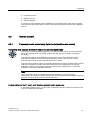
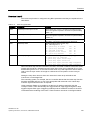
BICO symbols, representation, and description
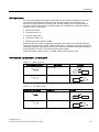
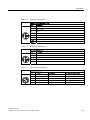
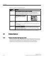
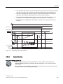
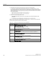
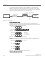
Table 2- 9
Binector symbols
Abbreviation and symbol
BI
Description
Function
Binector input
'DWDIORZ
3[[[[
)XQFWLRQ
%,
BO
Binector output
'DWDIORZ
U[[[[
)XQFWLRQ
%2
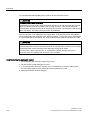
Table 2- 10
Connector symbols
Abbreviation and symbol
CI
Description
Connector input
Function
'DWDIORZ
3[[[[
)XQFWLRQ
&,
CO
Connector output
'DWDIORZ
)XQFWLRQ
U[[[[
&2
SINAMICS G110D
Operating Instructions, 2010-20-06, A5E02385577A2 AB
27
Introduction
2.3 Extended adaptation of parameters
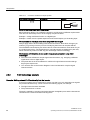
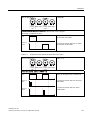
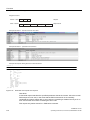
Table 2- 11
Connector and binector output symbols
Abbreviation and symbol
&2%2
Description
Function
Binector/connector output
'DWDIORZ
U[[[[
)XQFWLRQ
&2%2
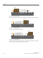
When do you need to use BICO technology?
BICO technology allows you to adapt the inverter to a wide range of different requirements.
This does not necessarily have to involve highly complex functions.
Example 1: Assign a different function to a digital input.
Example 2: Switch over the speed setpoint from the fixed frequency to the analog input.
What precautions should you take when using BICO technology?
Always apply caution when handling internal interconnections. Note which changes you
make as you go along since the process of analyzing them later can be quite difficult.
The STARTER commissioning tool offers various screens that make it much easier for you
to use BICO technology. The signals that you can interconnect are displayed in plain text,
which means that you do not need any prior knowledge of BICO technology.
What sources of information do you need to help you set parameters using BICO
technology?
● This manual is sufficient for simple signal interconnections, e.g. assigning a different
significance to the to digital inputs.
● The parameter list in the List Manual is sufficient for signal interconnections that go
beyond just simple ones.
● You can also refer to the function diagrams in the List Manual for complex signal
interconnections.
2.3.2
BICO technology: example
Example: Shifting a basic PLC functionality into the inverter
A conveyor system is to be configured in such a way that it can only start when two signals
are present simultaneously. These could be the following signals, for example:
● The light barrier has been activated
● The protective door is closed
The task is realized by inserting free blocks between the digital input 0 and the internal ON
command for the motor and interconnecting them.
28
SINAMICS G110D
Operating Instructions, 2010-20-06, A5E02385577A2 AB
Introduction
2.3 Extended adaptation of parameters
3 3>@
',
',
U
3
,QGH[>@
,QGH[>@
U
U
Figure 2-3
Example: Signal interconnection for interlock
Table 2- 12
Parameterizing an interlock
3
,QGH[>@
Parameter
Description
P0003 = 3
Enable expert access to parameters
P0700 = 2
Select the command source: Digital inputs
21
2))
P0701 (e.g.) = 99
Enable/"open" digital input 0 (DI0) for BICO parameterization
P0702 (e.g.) = 99
Enable/"open" digital input 1 (DI1) for BICO parameterization
P2800 = 1
Group enable all freely-programmable function blocks (FFB)
P2801 [In000] = 1
Individual enable of the AND function block
P2810 [In000] = 722.0
Connect the status of DI0 to the 2nd AND
P2810 [In001] = r0722.1
Connect the status of DI1 to the 2nd AND input
r0722.1 = Parameter that displays the status of digital input 1.
P0840 = r2811
Connect the AND output to the control command ON/OFF1
Explanations of the example
Open the default signal interconnection for BICO parameterization
The default setting P0701 = 1 indicates the following internal signal interconnection:
3
',
21
2))
U
Figure 2-4
Default parameterization
The setting P0701 = 99 means that a pre-assigned signal interconnection is disconnected
and therefore the connection opened for BICO parameterization.
3
',
21
2))
U
Figure 2-5
BICO parameterization
When P0701 = 99, the binector input of the ON/OFF1 function (P0840) is available for
activation by a signal source other than r0722.0 (in this case r2811).
',
U
Figure 2-6
3
,QGH[>@
,QGH[>@
3
U
21
2))
Interconnection after insertion of two functions
SINAMICS G110D
Operating Instructions, 2010-20-06, A5E02385577A2 AB
29
Introduction
2.3 Extended adaptation of parameters
Principle of connecting functions by means of BICO technology
A connection between two functions comprises a connector/binector and a BICO parameter.
Connections are always established with respect to the input of a particular function, which
means that the output of an upstream function must always be assigned to the input of a
downstream function. The assignment is always made by entering the number of the
connector/binector from which the required input signals are read in a BICO parameter.
30
SINAMICS G110D
Operating Instructions, 2010-20-06, A5E02385577A2 AB
Description
3.1
3
Overview of SINAMICS G110D Inverters
SINAMICS G110D Inverters
The SINAMICS G110D has been designed to provide an adaptable solution to conveyor
technology applications.
Each SINAMICS G110D Inverter is a complete Power Module and Control Unit in one
unique housing which is IP65 rated. The power output range extends from 0.75 kW to 7.5
kW.
The optional STARTER software allows commissioning of the Inverter using a PC with the
optional optical cables.
A range of additional, application-specific components are also available, for example,
braking resistors.
SINAMICS G110D
Operating Instructions, 2010-20-06, A5E02385577A2 AB
31
Description
3.2 Components of the Inverter system
3.2
Components of the Inverter system
The Inverter system
The Inverter is available in three frame sizes:
Frame size A (FSA)
6SL3511-0PE17-5AM0 - 0.75 kW
6SL3511-1PE17-5AM0 - 0.75 kW with repair switch
6SL3511-0PE21-5AM0 - 1.5 kW
6SL3511-1PE21-5AM0 - 1.5 kW with repair switch
6SL3511-0PE23-0AM0 - 3.0 kW
6SL3511-1PE23-0AM0 - 3.0 kW with repair switch
Figure 3-1
32
SINAMICS G110D FSA
SINAMICS G110D
Operating Instructions, 2010-20-06, A5E02385577A2 AB
Description
3.2 Components of the Inverter system
Frame size B (FSB)
6SL3511-0PE24-0AM0 - 4.0 kW
6SL3511-1PE24-0AM0 - 4.0 kW with repair switch
Figure 3-2
SINAMICS G110D FSB
Frame size C (FSC)
6SL3511-0PE25-5AM0 - 5.5 kW
6SL3511-1PE25-5AM0 - 5.5 kW with repair switch
6SL3511-0PE27-5AM0 - 7.5 kW
6SL3511-1PE27-5AM0 - 7.5 kW with repair switch
Figure 3-3
SINAMICS G110D FSC
The inverter is capable of controlling and monitoring the connected motor in a variety of
control modes (which can be selected as required). It supports communication with a local or
central controller as well as with monitoring devices.
To enable motors to operate with maximum reliability and flexibility, the Inverter features
state-of-the-art IGBT technology with pulse width modulation. The Inverter also features a
range of functions designed to offer a high degree of protection for the Inverter and the
connected motor.
SINAMICS G110D
Operating Instructions, 2010-20-06, A5E02385577A2 AB
33
Description
3.2 Components of the Inverter system
The Inverter is IP65 rated, which means it is totallyprotected against dust and protected
against low-pressure jets of water from all directions with limited ingress permitted.
Additional components of the Inverter system
In addition to the main Inverter, the following components are available:
Local/remote switch cover
The Local/remote switch coverallows the user to control the Inverter and the connected
motor directly from the Inverter. The Local/remote switch cover replaces the standard control
unit cover.
Order number: 6SL3555-0PL00-2AA0
IOP Hand-held Kit
The Hand-held Kit supplies the IOP with its own portable power supply which allows the IOP
to be used for series commissioning and diagnosis on a number of Inverters.
To connect the IOP Hand-held Kit to all decentralized SINAMICS Inverters, the RS232
optical cable is required - order number: 3RK1922-2BP00.
Order number: 6SL3255-0AA00-4HA0
34
SINAMICS G110D
Operating Instructions, 2010-20-06, A5E02385577A2 AB
Description
3.2 Components of the Inverter system
Memory Card
The memory card can be used for series commissioning of more than one Inverter and for
external data backup purposes.
Order number: 6SL3254-0AM00-0AA0.
Memory card holder
The memory card holder allows a memory card to be fitted to the control unit of the Inverter.
The memory card holder is located underneath the control unit cover. The memory card
holder is capable of reading and writing to both MMC and SD type memory cards.
Order number: 6SL3555-0PM00-0AA0.
SINAMICS G110D
Operating Instructions, 2010-20-06, A5E02385577A2 AB
35
Description
3.2 Components of the Inverter system
Optical cables
The optical cables in conjunction with the STARTER software allows the user to perform a
guided, computer-based commissioning of the Inverter. There are two types of optical
cables, the details are listed below:
● USB Optical cable - order number: 6SL3555-0PA00-2AA0
● RS232 optical cable - order number: 3RK1922-2BP00.
Adapter Plate
The adapter plate allows the conversion of the M200D motor-starter mounting centres to a
SINAMICS G110D configuration and vice versa.
Order number: 6SL3263-1GA20-0GA0.
Braking resistors
There are three different classes of braking resistors available for use with the Inverter.
Table 3- 1
SINAMICS G110D Braking resistors
Order Number
Description
Specification
For use with Inverter
6SL3501-0BE08-6AA0
G110D Braking Resistor
390 ohms / 86 watts average
0.75 kW & 1.5 kW
6SL3501-0BE12-1AA0
G110D Braking Resistor
160 ohms / 210 watts average
3 kW & 4 kW
6SL3501-0BE14-1AA0
G110D Braking Resistor
82 ohms / 410 watts average
5.5 kW & 7.5 kW
Spare parts
The following spare parts are available for the inverter:
● Fan assembly, complete with all necessary fixings.
Order number: 6SL3500-0TF01-0AA0.
● Accessories kit - this contains all the caps and seals used with the Inverter.
Order number: 6SL3500-0TK01-0AA0.
36
SINAMICS G110D
Operating Instructions, 2010-20-06, A5E02385577A2 AB
Connection
4.1
4
Procedure for installing the Inverter
Prerequisites for installing the Inverter
Before you install the Inverter, check that the following preconditions are fulfilled:
● Are the ambient conditions permissible?
● Are the components required for the installation available?
● Are all the necessary tools and spare parts available?
● Have the cables and wires been routed in accordance with the applicable regulations?
● Do the minimum distances from other equipment comply with the specifications?
Installation procedure
● Using the information from the drill pattern, mark the necessary fixing points for the
Inverter onto the area on which the Inverter is to be mounted.
● Ensure that the correct orientation of the Inverter is observed.
● Ensure that the ambient operating conditions are observed.
● Ensure that the correct fuse protection is installed.
● Install the memory card holder and memory card if required.
● Construct the necessary cables (in accordance to the information provided).
● Connect the AS-i cable to the AS-i bus.
● For commissioning, connect either the IOP Hand-held Kit or a PC utilizing the STARTER
software and the optical cables.
The installation is now completed and the commissioning of the Inverter can now
commence.
SINAMICS G110D
Operating Instructions, 2010-20-06, A5E02385577A2 AB
37
Connection
4.2 General layout of SINAMICS G110D
4.2
General layout of SINAMICS G110D
General layout of SINAMICS G110D
5HSDLUVZLWFK
%UDNLQJUHVLVWRUFRQQHFWLRQKDWFK
2SWLFDO3&FRQQHFWLRQ
6WDWXV/('V
$QDORJ',3VZLWFKHVXQGHUQHDWK&8FRYHU
2SWLRQDO00&6'FDUGKROGHUXQGHUQHDWK&8FRYHU
$6LGHYLFHDGGUHVVSRUWXQGHUQHDWK&8FRYHU
Figure 4-1
38
0DLQVVXSSO\FRQQHFWLRQ
0RWRUEUDNHDQGWHPSHUDWXUHVHQVRUFRQQHFWLRQ
$6LLQSXWFRQQHFWLRQ
$QDORJLQSXW$,
'LJLWDOLQSXWV',',
'LJLWDOLQSXWV',',
+HDWVLQN
SINAMICS G110D Inverter
SINAMICS G110D
Operating Instructions, 2010-20-06, A5E02385577A2 AB
Connection
4.3 Removal of CU area cover and braking resistor connection hatch
4.3
Removal of CU area cover and braking resistor connection hatch
Removal of CU area cover and braking resistor connection hatch
Should the CU area cover require to be removed, for example, to fit a Memory Card, it
should be removed as shown in the diagram below. The braking resistor connection hatch is
removed using the same technique.
CAUTION
Seals fitted correctly
Should the CU area cover or the braking resistor connection hatch be removed from the
Inverter, it is important to ensure that the seals around these areas are fitted properly when
reassembling the Inverter to ensure the IP65 rating.
TN and TT mains supplies
The SINAMICS G110D Inverter with the Class A integrated mains filter is only suitable for
operation on TN and TT mains supplies.
7RUTXH1POEILQ
%UDNLQJUHVLVWRUFRQQHFWLRQKDWFK
Figure 4-2
&8DUHDFRYHU
Removal of CU area cover and braking resistor connection hatch
SINAMICS G110D
Operating Instructions, 2010-20-06, A5E02385577A2 AB
39
Connection
4.4 Drill pattern for the SINAMICS G110D
4.4
Drill pattern for the SINAMICS G110D
Drill pattern for the SINAMICS G110D Inverter
The Inverter has an identical drill pattern for all frame sizes. The drill pattern, depth and
tightening torques are shown in the diagram below.
PP
ZLWKRXWUHSDLUVZLWFKZLWKUHSDLUVZLWFK
)6$GHSWK
PP PP
)6%GHSWK
PP PP
)6&GHSWK
PP PP
)L[LQJPHWKRG
[0EROWV
[0QXWV
[0ZDVKHUV
PP
PP
6,1$0,&6*')UDPHVL]HV$%DQG&
7LJKWHQLQJWRUTXH1POEILQZLWKZDVKHUVILWWHG
PP
Figure 4-3
40
Drill pattern SINAMICS G110D
SINAMICS G110D
Operating Instructions, 2010-20-06, A5E02385577A2 AB
Connection
4.5 Mounting orientation
4.5
Mounting orientation
Correct mounting orientation of the Inverter
In the figure below the correct mounting orientation of the Inverter is shown.
Figure 4-4
Correct Inverter orientation
SINAMICS G110D
Operating Instructions, 2010-20-06, A5E02385577A2 AB
41
Connection
4.6 Ambient operating conditions
4.6
Ambient operating conditions
Temperature
The operating temperature range is shown diagramatically in the figure below:
3HUPLVVLEOHRXWSXWFXUUHQW
>@
Figure 4-5
>r&@
>r)@
$PELHQWRSHUDWLQJWHPSHUDWXUH
Power derating for temperature
Humidity range
Relative air humidity for the Inverter is ≤ 95 % non-condensing.
Altitude
If the Inverter is to be installed at an altitude > 1000 m (> 3280 ft) derating will be required.
The figures below show the derating required according to altitude.
3HUPLVVLEOHRXWSXWFXUUHQW
>@
3HUPLVVLEOHLQSXWYROWDJH
>@
Figure 4-6
>P@
,QVWDOODWLRQDOWLWXGH
DERYHVHDOHYHO
>P@
,QVWDOODWLRQDOWLWXGH
DERYHVHDOHYHO
Derating for altitiude
Shock and vibration
Do not drop the Inverter or expose to sudden shock. Do not install the Inverter in an area
where it is likely to be exposed to constant vibration.
42
SINAMICS G110D
Operating Instructions, 2010-20-06, A5E02385577A2 AB
Connection
4.7 SINAMICS G110D Specifications
Electromagnetic radiation
Do not install the Inverter near sources of electromagnetic radiation.
Atmospheric pollution and water
When fully assembled the inverter has an IP65 rating. This means that the inverter is totally
protected against dust and low pressure jets of water. Any unused connections should be
covered with the correct sealing caps to ensure the IP65 rating.
4.7
SINAMICS G110D Specifications
SINAMICS G110D specifications
Table 4- 1
Rated Output, Input and Fuses
Product
Frame
size
6SL3511-…
Rated output
HO
Fuse
Rated output
current
Rated input
current
Circuit breakers
3NA3…
kW
hp
A
A
A
Type
Order Number
0PE17-5AM0
A
0.75
1
2.3
2.0
10
803
-
3RV1021-1FA10
0PE21-5AM0
A
1.5
1.5
4.3
3.9
10
803
-
3RV1021-1JA10
0PE23-0AM0
A
3
4
7.7
7.0
16
805
-
3RV1021-4AA10
0PE24-0AM0
B
4
5
10.2
9.1
20
807
-
3RV1021-4BA10
0PE25-5AM0
C
5.5
7.5
13.2
12.2
20
807
-
3RV1031-4EA10
0PE27-5AM0
C
7.5
10
19
17.9
32
812
-
3RV1031-4FA10
For further technical information, please refer to the Operating Instructions.
Group fusing
Group fusing is where one circuit breaker or fuse is intended to provide protection for two or
more devices. The protection device is called a branch circuit protection (BCP) device.
For more information, please read the following FAQ:
http://support.automation.siemens.com/WW/view/en/35935349
For additional information please see the following FAQs:
http://support.automation.siemens.com/WW/view/en/14399444
http://support.automation.siemens.com/WW/view/en/23995621
SINAMICS G110D
Operating Instructions, 2010-20-06, A5E02385577A2 AB
43
Connection
4.8 Cables and connections
4.8
Cables and connections
Connections and cables
WARNING
Switches and contactors
Under no circumstances shall any kind of switch or contactor be placed in the circuits
between the Inverter and the motor. For maintenance, ensure that the motor cable is
unplugged at the Inverter.
Temperature sensor and brake module connections
The temperature sensor and brake module connections are at DC link negative potential.
Appropriate precautions against touching these connections and appropriate insulation on
the cables must be used. The motor terminal box must be kept closed whenever the mains
is applied to the Inverter. Cables that are not used should be individually insulated and not
earthed.
The following block diagram and tables describe the details and limitations of the
connections of the inverter.
Cable lengths
All inverters will operate at full specification with motor cable lengths as follows:
● Screened - 15 m (49 ft)
● Unscreened - 30 m (98 ft)
Note
Brake voltage 180VDC (400VAC with rectifier)
The brake output of the Inverter is designed to be connected directly to the coil of the
brake within the motor, that is, no rectifier module is required within the motor. For
operation of the Inverter on a 400VAC supply the brake should be rated for approximately
180VDC (400VAC with rectifier). The brake voltage is dependent on the mains supply
voltage (brake voltage = mains voltage x 0.45).
The UL approved current rating for the brake output is 600mA.
The maximum current rating for the brake output without UL is 1A.
Brake voltage 205VDC (230VAC with rectifier)
The brake output of the Inverter is designed to be connected directly to the coil of the
brake within the motor, that is, no rectifier module is required within the motor. For
operation of the Inverter on a 400VAC supply the brake should be rated for approximately
205VDC (230VAC with rectifier). The brake voltage is dependent on the mains supply
voltage (brake voltage = mains voltage x 0.9).
The UL approved current rating for the brake output is 600mA.
The maximum current rating for the brake output without UL is 1A.
For operation of a 205VDC brake the parameter P1215 must be set P1215=2.
44
SINAMICS G110D
Operating Instructions, 2010-20-06, A5E02385577A2 AB
Connection
4.8 Cables and connections
Analog input DIP-switches
The analogue input can be configured as an additional digital input. In order to achieve this
AIN- (X15.4) should be connected to AIN 0V (X15.3) and the digital input should be
connected to AIN+ (X15.2). To make this easier a switch has been provided under the
control unit cover that, when operated, makes this connection internally. It is also possible to
select whether connection X15.1 provides a 10V (10mA) supply, normally used for an
analogue input, or a 24V (25mA) supply, normally used for a digital input. See block diagram
below for details.
Auxillary (AUX) power
To operate this product, 24V power supplies need to be provided on both the AS-i + / AS-i and AUX 24V / 0V pins of connector X3. When the product is connected to an AS-i network
the 24V power supply on the AS-i + / AS-i - pins is provided by the AS-i network itself. In this
case additionally a separate independent 24V power supply must be provided on the AUX
24V / 0V pins.
If the product is not connected to an AS-i network then a 24V power supply still needs to be
connected to the AS-i + / AS-i - pins. This can be the same power supply as connected to
the AUX 24V / 0V pins as shown in the block diagram below.
SINAMICS G110D
Operating Instructions, 2010-20-06, A5E02385577A2 AB
45
Connection
4.8 Cables and connections
Block diagram
$&9
3(
$6L%XV&RQQHFWLRQ
///
3(
;$6L
;$8;9
;$6L
;$8;9
;)XQFWLRQDO(DUWK
;
;89RU89
;$,1
;$,1989
;$,1
;)XQFWLRQDO(DUWK
;
;
&38
;
;
',
;
9 ;
',
;
',
;
9 ;
',
;89
;'LJLWDO,QSXW
;89
;'LJLWDO,QSXW
;)XQFWLRQDO(DUWK
;89
;'LJLWDO,QSXW
;89
;'LJLWDO,QSXW
;)XQFWLRQDO(DUWK
89:
%UDNH
3(
7HPSHUDWXUHVHQVRU
:KHQWKH6,1$0,&6*'LVXVHGDVD
VWDQGDORQH,QYHUWHUDQGLVQRWFRQQHFWHGWRDQ
$6LQHWZRUNDQH[WHUQDO9VXSSO\PXVWEH
XVHG
0
3LQV
$6L ,QWKLVFDVHWKHH[WHUQDO9VXSSO\LVFRQQHFWHG
DVVKRZQLQWKHGLDJUDPRSSRVLWHWRWKH$6L
EXVFRQQHFWLRQRIWKH,QYHUWHU
9
$8;9
9
$6L
$8;9 )XQFWLRQDO(DUWK $QDORJ',36ZLWFK
/LQN;WR;
; 89
'HIDXOWVHWWLQJV
1RLQWHUQDOOLQN
;WR;
; 9
,PSRUWDQW
:KHQWKH,QYHUWHULVRSHUDWLQJRQDQ$6LQHWZRUNWKH$6LSRZHUVXSSO\PXVWEHEHWZHHQ9DQG97KHDX[SRZHUVXSSO\>EODFNFDEOH@LV
DOZD\V9s
,IWKH,QYHUWHULVRSHUDWLQJLQGHSHQGHQWO\RIDQ$6LQHWZRUNWKHH[WHUQDOSRZHUVXSSO\UDQJHFDQEH9s
7RDFKLHYHD8/FRPSOLDQWLQVWDOODWLRQWKHH[WHUQDO9GFVXSSO\PXVWEH&ODVVRUOLPLWHGYROWDJHFXUUHQWDFFRUGLQJWR8/ZKHQWKH6,1$0,&6
*'LVFRQQHFWHGWRDQ$6LQHWZRUNWKHH[WHUQDO9SRZHUVXSSO\PXVWEH3(/9DFFRUGLQJWR,(&
Figure 4-7
46
SINAMICS G110D block diagram
SINAMICS G110D
Operating Instructions, 2010-20-06, A5E02385577A2 AB
Connection
4.8 Cables and connections
Cable, connectors and tools specifications
The detailed specifications for the cables, connectors and tools required to manufacture the
necessary cables for the SINAMICS G110D are listed in the following tables.
NOTICE
NFPA compatibility
These devices are intended only for installation on industrial machines in accordance with
the "Electrical Standard for Industrial Machinery" (NFPA79). Due to the nature of these
devices they may not be suitable for installation in accordance with the "National Electrical
Code" (NFPA70).
Table 4- 2
Tools
Harting part number
Crimp tool (Q8/0 and Q4/2)
0999-000-0110
Removal tool (Q8/0)
0999-000-0319
Removal tool (Q4/2)
0999-000-0305
No special tools are required for the Control Unit connectors
Table 4- 3
Control Unit connectors
Connector
Binder part numbers
Straight connector
Right-angle connector
ASI (M12 )
99-0436-14-05
99-0436-24-05
Digital input and Analog output (M12 )
99-0437-14-05
99-0437-24-05
Table 4- 4
Power
rating
Mains supply connector
cable size
cable type
All connector parts are Harting Q4/2
Shell
Crimp
size
Crimp number
Hood
Gland/Seal
Harting Q4/2
1.5 mm2
16 AWG
0932 000 6204
0912 008 0527
0900 000 5059
1912 008 0526
1900 000 5190
1.50 kW
1.5 mm2
16 AWG
(3+E) YY
Unscreened
3.00 kW
mm2
2.5
14 AWG
(3+E) YY
Unscreened
2.5 mm2
14 AWG
0932 000 6205
4 mm2
12 or 10
AWG
(3+E) YY
Unscreened
4 mm2
12 or 10
AWG
0932 000 6207
0.75 kW
4.00 kW
5.50 kW
7.50 kW
0912 006 3141
4 x crimps are required for each inverter; use 75°C copper wire only
SINAMICS G110D
Operating Instructions, 2010-20-06, A5E02385577A2 AB
47
Connection
4.8 Cables and connections
Table 4- 5
Motor connector
Power
rating
cable
size
Belcom
"DESINA"
Cable No.
Shell
Crimp
size
Crimp number
Hood
Gland/Seal
0.75 kW
1 mm2
18 AWG
13EBN17Z08P
Harting Q8/0
0933 000 6105
1912 008 0502
1912 000 5057
2.5 mm2
14 AWG
13EBN13Z08P
0912 008
3001
1 mm2
18 AWG
2.5 mm2
14 AWG
0933 000 6102
1912 008 0528
4 mm2
12 or 10
AWG
13EBN11Z08P
4 mm2
12 or 10
AWG
0933 000 6107
Lapp
MS-SCM25x1.5
1.50 kW
3.00 kW
4.00 kW
5.50 kW
7.50 kW
All connector parts are Harting Q8/0
53112640
4 x crimps are required for each inverter for the motor connections; use 75°C copper wire only
Table 4- 6
Temperature sensor and EM brake
Power
rating
cable
size
Belcom
"DESINA"
Cable No.
Temperature sensor pair
EM Brake pair
Crimp size
Crimp number
Crimp size
Crimp number
0.75 kW
1 mm2
18 AWG
13EBN17Z08P
0.75 mm2
20 AWG
0933 000 6114
0.75 mm2
20 AWG
0933 000 6114
2.5 mm2
14 AWG
13EBN13Z08P
1 mm2
18 AWG
0933 000 6105
1 mm2
18 AWG
0933 000 6105
4 mm2
12 or 10
AWG
13EBN11Z08P
1 mm2
18 AWG
0933 000 6105
1.5 mm2
18 AWG
0933 000 6104
1.50 kW
3.00 kW
4.00 kW
5.50 kW
7.50 kW
2 x crimps are required for each auxiliary signal pair; use 75°C copper wire only
Connection specifications
Table 4- 7
3(
48
Mains supply and motor output specifications
Mains supply
Motor output
Pin
Function
Pin
Function
1
L1
1
U
2
L2
2
Not connected
3
L3
3
W
4
-
11
-
12
-
PE
Protective Earth
3(
4
EM Brake (-)
5
Temperature sensor (+)
6
EM Brake (+)
7
V
8
Temperature sensor (-)
PE
Protective Earth
Type
HAN Q4/2 (Male)
Type
HAN Q8 (Female)
Spec.
3AC 380V...500V ±
10%
Spec.
-
SINAMICS G110D
Operating Instructions, 2010-20-06, A5E02385577A2 AB
Connection
4.8 Cables and connections
Table 4- 8
Digital input specifications
Digital input (2 sockets, 4 DIs)
Pin
Table 4- 9
Function
1
+24 V (25mA max.)
2
DI1 or DI3
3
U0V
4
DI0 or DI2
5
Functional Earth
Shield
Functional Earth
Type
M12 - 5 pole (Female)
Spec
PNP, SIMATIC-compatible, low < 5 V, high > 10 V, max. input voltage 30V
Analog input specifications
Analog connections
Table 4- 10
Pin
Function
1
10V (10 mA) / 24 V
2
AIN+
3
0V
4
AIN-
5
Functional Earth
AS-i connector specifications
ASI connections
Pin
Function
Description
AS-i system cable colour
1
ASi+
AS-i positive
Yellow
2
AUX-
Auxilary 0 V
Black
3
ASi-
AS-i negative
Yellow
4
AUX+
Auxilary 24 V
Black
5
Function earth
Earth connection
-
SINAMICS G110D
Operating Instructions, 2010-20-06, A5E02385577A2 AB
49
Connection
4.9 Configuring the AS-i slave
4.9
Configuring the AS-i slave
Overview
Before data transfer can take place between the AS-i Master and the slave devices each
slave must be assigned an address. The address of a AS-i slave can be assigned using the
following methods:
● Addressing off-line using the Siemens Addressing Programmer
● Addressing on-line using the controlling system, such as a PLC via the AS-i Master (it
should be noted that only one slave with address 0 may be present on the bus if this
method is to be implemented).
The addresses are designated numbers between 1 and 31, with each slave device having a
preset address of 0. If the AS-i master detects a slave with address 0, it recognizes the
device and can automaticallly assign an address to the device and integrate the device into
the AS-i network (If more than one slave device has the address 0, the automatic address
assignment and integration is not possible).
Note
Profile 3.0
Under AS-i Profile 3.0 it is possible to address 62 digital or 62 analog slave devices or a
combination of both digital and analog but not exceeding a total of 62 slave devices. This is
accomplished by using the A/B address system. For example, two slaves can assigned as
number 1 slave device, by assigning them as 1A and 1B.
The addresses of the slave devices do not have to be sequential, for example the first slave
device can have the address 21, the next 10.
Prior to the installation and commissioning of the Inverter, the AS-i communications and
devices have to be set-up correctly. The equipment shown in the table below will be
necessary for the successful integration of more than one Inverter onto the AS-i bus network.
50
SINAMICS G110D
Operating Instructions, 2010-20-06, A5E02385577A2 AB
Connection
4.9 Configuring the AS-i slave
Table 4- 11
Equipment for installation of SINAMICS G110D (AS-i)
Item
Order Number
Address cable
3RK1901-3HA01
AS-i address programmer
3RK1904-2AB01
AS-i connection kit
3RK1901-1NR21
SINAMICS G110D
Operating Instructions, 2010-20-06, A5E02385577A2 AB
51
Connection
4.9 Configuring the AS-i slave
Typical AS-i network structure
In the diagram below a typical AS-i network is shown to help visualise the structure and
arrangement of an AS-i network.
2QO\RQHPDVWHUFDQEH
RSWLPDOO\FRQQHFWHGWRDQ
$6LOLQH
6,0$7,&
6,027,21
352),1(7
,QGXVWULDO(WKHUQHW
'3$6L)/LQN
352),%86'3
$6,QWHUIDFH0DVWHU
'3$6L/,1.$GYDQFHG
0XOWL
3DQHO
$6,QWHUIDFH0DVWHU
6
'3$6,QWHUIDFH/LQN(
6,027,21&
$6,QWHUIDFH
SRZHUVXSSO\
6
6
6
$6,QWHUIDFHGLVWULEXWRU
ZLWKRXW$6,QWHUIDFHFKLS
,($6L/,1.31,2
$6,QWHUIDFH
SRZHUVXSSO\
5HSHDWHU
9'&
SRZHUVXSSO\
/2*2
0D[$6LFDEOHOHQJWK
SHUVHJPHQW
PZLWKRXW([WHQVLRQ3OXJ
PZLWK([WHQVLRQ3OXJ
2SHUDWRU
FRQWURO
SDQHO
6DIHVODYHZLWK
(0(5*(1&<
6723
6LJQDO
HYDOXDWLRQ
$6,QWHUIDFHGLVWULEXWRU
ZLWKRXW$6,QWHUIDFHFKLS
($PRGXOH
GLJLWDODQDORJ
$6,QWHUIDFH
0D[$6LFDEOHOHQJWK
SHUVHJPHQW
PZLWKRXW([WHQVLRQ3OXJ
PZLWK([WHQVLRQ3OXJ
5$
&RPSDFW
VWDUWHU
,3
&RPSDFWVWDUWHU
,3
$6L([WHQVLRQ3OXJ
IRUVHJPHQWOHQJWK
XSWRP
6DIHW\
PRQLWRU
Figure 4-8
52
Example AS-i configuration
SINAMICS G110D
Operating Instructions, 2010-20-06, A5E02385577A2 AB
Connection
4.9 Configuring the AS-i slave
Addressing the AS-i device
To address the AS-i device (in this case, the Inverter), the following actions should be
performed.
CAUTION
AS-i Master
The AS-i Master must be disconnected from the network prior to addressing any AS-i
slaves. If the AS-i Master is connected to the network during the addressing process, the
addressing of an AS-i slave will not be possible.
Addressing Unit
When assigning the address of the slaves in the Inverter with the Addressing Unit, the
digital inputs and analog input must be disconnected to prevent the Addressing Unit from
being overloaded by their power consumption.
When the Addressing Unit is plugged into the device address port of the Inverter; the AS-i
communications are terminated automatically. Therefore there is no requirement to
disconnect the M12 AS-i connection on the Inverter.
1. Connect the M12 connector to the Inverter AS-i port ①.
2. Connect the AS-i cable to the M12 branch ②.
3. Remove the Control Unit cover ③.
4. Connect the Address Programmer to the AS-i addressing port on the Inverter ④.
5. The address of the Inverter (as a slave device) can now be completed. See next section
for full instructions on address the slaves using the Address Programmer.
6. Refit the Control Unit cover, ensure that the seals are correctly in place to preserve the
Inverter IP65 rating.
SINAMICS G110D
Operating Instructions, 2010-20-06, A5E02385577A2 AB
53
Connection
4.9 Configuring the AS-i slave
Figure 4-9
54
Addressing the ASi slave
SINAMICS G110D
Operating Instructions, 2010-20-06, A5E02385577A2 AB
Connection
4.10 Using the AS-i Programmer
4.10
Using the AS-i Programmer
Setting the slave address with the AS-i Address Programmer
The Inverter contains two logical AS-i slaves. Either slave can be assigned an address in the
range 1A...31A or 1B...31B. The addresses can be allocated to the slaves sequentially, for
example, 3A and 4A, 10B and 11B or they can occupy the same number using extended
addressing, for example, 20A and 20B. If necessary they can have completely different
unassociated addresses, for example, 14A and 16B.
The decision on how to allocate these addresses must also take into account the addressing
used in the PLC program by either adherence to the memory map of the AS-i master or the
way in which the inputs and outputs can be allocated by the PLC hardware configuration.
The default address of both slaves is 0.
Setting the AS-i address of slave 1
1.
Plug the AS-i Programmer into the addressing socket of the Inverter.
2.
Turn the dial on the Programmer to the ADDR
position. The display will indicate that this mode has
been selected.
3.
Press the
button; the screen will display the
text, SEt 0 with a small flashing 0 to the left of the
display.
4.
Press the
button until you reach the required number.
and
simultaneously, you can toggle between A and B
By pressing both the
identifiers of the address.
5.
Press the
address.
button to confirm the selected
ProG is momentarily displayed, followed by AddrES.
The number allocated to slave 1 is now shown at the
bottom of the display.
SINAMICS G110D
Operating Instructions, 2010-20-06, A5E02385577A2 AB
55
Connection
4.10 Using the AS-i Programmer
Setting the AS-i address of slave 2
1.
Press the
button; the dislay shows the text
SEArcH followed by uSE 0.
A small 0 is displayed to the left of the display and
the number of the first slave that has already been
allocated to slave 1 is shown at the bottom of the
display.
2.
Press the
button to select this number.
SEt 0 appears and the small 0 in the left of the
display starts flashing.
3.
Press the
button until you reach the required number.
and
simultaneously, you can toggle between A and B
By pressing both the
identifiers of the address.
4.
Press the
button to accept this number.
ProG is displayed briefly.
Both of the numbers allocated to the slaves are now
displayed in the lower part of the screen.
Changing existing addresses of the AS-i slaves
If the allocated addresses used two different numbers, for example, 10A and 11A, then if one
of the slave addresses is reset to 0 the other slave is not affected.
If the allocated addresses use the same number, for example, 20A and 20B, then if one
slave addresses is reset to 0, then both slaves numbers will be reset to 0.
Modifying an existing address of a single slave within the Inverter will not affect the address
of the other slave.
To change an existing address of a slave, the following procedure should be performed:
56
1.
Plug the AS-i Programmer into the addressing socket of the Inverter
2.
Turn the dial on the Programmer to the ADDR
position. The display will indicate that this mode has
been selected.
SINAMICS G110D
Operating Instructions, 2010-20-06, A5E02385577A2 AB
Connection
4.10 Using the AS-i Programmer
3.
Press the
button; the screen will display uSE
and the number of the lower addressed slave.
The existing slave addresses are shown at the
bottom of the display.
4.
Press the
5.
button; the display now shows SEt.
Press the
The selected number will begin to flash.
6.
Press the
and
buttons to select the new
slave address number.
7.
Press the
and
buttons to select the slave address number to be changed.
button to confirm the new address.
ProG is displayed briefly followed by confirmation of
the address change.
SINAMICS G110D
Operating Instructions, 2010-20-06, A5E02385577A2 AB
57
Connection
4.10 Using the AS-i Programmer
58
SINAMICS G110D
Operating Instructions, 2010-20-06, A5E02385577A2 AB
Commissioning
5.1
5
Typical commissioning scenarios
Alternative commissioning options
The functions of the Inverter are activated and configured using parameters. Parameters can
either be accessed from the operator control/display instrument (Operator Panel) or using
the STARTER software from the PC using the appropriate Inverter interface.
Parameter information and data can also be accessed and modified over the AS-interface.
For further details please see the section "Operation in fieldbus system".
Inverters can also be parameterized by saving the valid Inverter parameter set on an
SD/MMC memory card then transferring it to a different Inverter with the same configuration
and function.
The commissioning scenarios listed below are described in the following sections:
● Commissioning, using the factory settings
● Commissioning with the STARTER software
● Commissioning using the Operator Panel
● Data backup with the SD/MMC memory card
Users can access the inverter parameters via the following interfaces
SINAMICS G110D
Operating Instructions, 2010-20-06, A5E02385577A2 AB
59
Commissioning
5.2 Restoring the factory settings
67$57(5
XVLQJ86%RSWLFDOFDEOH
,23
XVLQJ56RSWLFDOFDEOH
3&LQYHUWHU
,23+DQGKHOGNLW
Figure 5-1
5.2
6'00&
Communications interfaces
Restoring the factory settings
If nothing else works, restore the factory settings!
You can restore the factory settings using parameter P0970.
60
Parameter or
procedure
Description
P0003 = 1
User access level
1: Standard level
P0010 = 30
Commissioning parameter
30: Factory setting, parameter transfer
P0970 = 1
Restore factory settings
1: Restore the factory parameter settings
IOP - select factory
restart from the extras
menu.
The IOP will display a message stating that a factory reset is taking place
and display a progress bar. When completed the display will display a
message that the factory reset has been successfully completed.
STARTER
Displays a progress bar.
SINAMICS G110D
Operating Instructions, 2010-20-06, A5E02385577A2 AB
Commissioning
5.3 Preparing for commissioning
Note
Data transfer is interrupted while the factory parameter settings are being restored.
The following parameters remain unchanged even after the factory settings have been
restored:
P0014 Storage mode
P0100 Europe / North America
P0201 Power stack code number
Communication parameters
Power-Module-specific data
5.3
Preparing for commissioning
Prerequisites: before you start
Before you start parameterization, you should clarify the following issues about
commissioning your application.
Are the factory settings sufficient for your application?
Check which factory settings can be used and which need to be changed (see Section
'Commissioning with factory settings'). When doing so, you may find that you only need to
change just a few parameters.
Which motor are you using? [P0300]
● A synchronous or induction motor?
The SINAMICS Inverters are preset in the factory for applications using 4-pole three-phase
induction motors that correspond to the performance data of the frequency inverter.
Motor data / data on the motor rating plate
If you use the STARTER software and a SIEMENS motor, you only have to specify the
Order No of the motor. In all other cases, you must read-off the data from the motor rating
plate and enter the data into the appropriate parameters.
SINAMICS G110D
Operating Instructions, 2010-20-06, A5E02385577A2 AB
61
Commissioning
5.3 Preparing for commissioning
P0305
P0310
P0304
3~Mot
1LA7130-4AA10
No UD 0013509-0090-0031
P0307
1325 IP 55
IM B3
50 Hz
230/400 V Δ/Υ
60 Hz
460 V
5.5kW
19.7/11.A
6.5kW
10.9 A
Cos ϕ 0.81
1455/min
Cos ϕ 0.82
1755/min
Δ/Υ 220-240/380-420 V
Υ 440-480
19.7-20.6/11.4-11.9 A
11.1-11.3 A
P0308
Figure 5-2
TICI F
EN 60034
P0311
95.75%
45kg
P0309
Rating plate data as parameters
NOTICE
Information about installation
The rating plate data that you enter must correspond to the connection type of the motor
(star/delta), i.e. with a delta motor connection, the delta rating plate data must be entered.
In which region of the world is the motor used? - Motor standard [P0100]
● Europe ICE: 50 Hz [kW] - factory setting
● North America NEMA: 60 Hz [hp] or 60 Hz [kW]
What is the prevailing temperature where the motor is operated? [P0625]
● Motor ambient temperature [P0625], if it differs from the factory setting = 20° C.
What control mode do you want to use for your application? [P1300]
There are variety of settings for P1300; the default being 0, which is V/f with linear
characteristic. This setting is suitable for most applications. For further information, refer to
the Parameter List for the SINAMICS G110D.
What command and setpoint sources are you using?
The command and setpoint sources that are available depend on the Inverter. The
SINAMICS G110D by default uses the fieldbus interface.
62
SINAMICS G110D
Operating Instructions, 2010-20-06, A5E02385577A2 AB
Commissioning
5.3 Preparing for commissioning
● Possible command sources [P0700]
– Operator Panel
– Fieldbus (default setting for the SINAMICS G110D Inverters)
– Local digital inputs/switches
● Possible setpoint sources [P1000]
– Motorized potentiometer
– Analog setpoint
– Fixed frequency (default setting for the SINAMICS G110D Inverters)
– Fieldbus
Minimum/maximum frequency of the motor
The minimum and maximum frequency with which the motor operates or is limited
regardless of the frequency setpoint.
● Minimum frequency [P1080] - factory setting 0 Hz
● Maximum frequency [P1082] - factory setting 50 Hz
Ramp-up time and ramp-down time
The ramp-up and ramp-down time define the maximum motor acceleration when the speed
setpoint changes. The ramp-up and ramp-down time is the interval between motor standstill
and the maximum frequency, or between the maximum frequency and motor standstill.
● Ramp-up time [P1120] - factory setting 10 s
● Ramp-down time [P1121] - factory setting 10 s
SINAMICS G110D
Operating Instructions, 2010-20-06, A5E02385577A2 AB
63
Commissioning
5.4 Prerequisites of using the factory settings
5.4
Prerequisites of using the factory settings
Prerequisites for using the factory settings
In simple applications, commissioning can be carried out just using the factory settings. This
section explains what prerequisites must be fulfilled for this purpose and how they are
fulfilled.
1. The Inverter and motor must match one another; otherwise you must perform a complete
quick commissioning (this can be performed using the IOP Hand-held Kit or STARTER).
2. The binary and analog inputs must be connected in accordance with the requirement of
the application.
3. You then have to "tell" the Inverter the following,
– the source of its commands:
- from an operator panel,
- from the digital inputs
- from the fieldbus interface (default setting of the SINAMICS G110D)
You can change this command source using parameter P0700 if the factory setting is
not appropriate for your application.
– where it gets its speed setpoint (setpoint source)
- from an analog input (analog setpoint)
- as fixed frequency from a digital input (default setting of the SINAMICS G110D)
- from the fieldbus interface
You can change this frequency setpoint source using parameter P1000 if the factory
setting is not appropriate for your application.
5.5
Factory settings for the Inverter
Default command and setpoint sources
Inverters used in automation solutions have the appropriate fieldbus interfaces. These
Inverters are preset in the factory so that the appropriate control and status signals can be
exchanged using the fieldbus interface.
Table 5- 1
Command and setpoint sources
Parameter
Description
P0700 = 6
Select the command source
Fieldbus
P1000 = 3
Select the setpoint source
Fixed frequencies
64
SINAMICS G110D
Operating Instructions, 2010-20-06, A5E02385577A2 AB
Commissioning
5.5 Factory settings for the Inverter
Table 5- 2
Factory setting of additional important parameters
Parameter
Factory setting
Meaning of the factory setting
Function
Access
level
P0003
1
Access to the most frequently used Selecting the user access level
parameters
1
P0004
0
All parameters are displayed
Parameter filter: filters parameters in
accordance with the functionality
1
P0010
0
Ready to be entered
Commissioning parameter
1
P0100
0
Europe [50 Hz]
Frequency of the regional supply network
IEC, Europe
NEMA, North America
1
P0300
1
Induction motor
Select the motor type (induction motors /
synchronous motor)
2
P0304
400
[V]
Rated motor voltage
(in accordance with rating plate in V)
1
P0305
depends on
the
Power Module
[A]
Rated motor current
(in accordance with rating plate in A)
1
P0307
depends on
the
Power Module
[kW/hp]
Rated motor output
(in accordance with the rating plate in
kW/hp)
1
P0308
0
[cos phi]
Rated motor power factor (in accordance
with rating plate in cos 'phi') when P0100 =
1.2, then P0308 is irrelevant
1
P0309
0
[%]
Rated motor efficiency (in accordance with
rating plate in %) when P0100 = 0, then
P0309 is irrelevant
1
P0310
50
[Hz]
Rated motor frequency
(in accordance with rating plate in Hz)
1
P0311
1395
[rpm]
Rated motor speed
(in accordance with rating plate in rpm)
1
P0335
0
Non-ventilated: Shaft-mounted fan
in the motor
Motor cooling (specify the motor cooling
system)
2
P0625
20
°C
Ambient temperature of motor
3
P0640
200
[%]
Motor overload factor (entered in % referred
to P0305)
2
P0700
6
6 (default setting)
Select the command source
1
P0727
0
DI0: On / off
DI1: Direction reversal
Control response when the motor starts
(start, stop, reverse)
3
P0970
0
Blocked
Restore factory settings
1
P1000
3
Fixed frequencies
Select the source of the frequency setpoint
(setpoint input)
1
P1080
0
[Hz]
Minimum frequency
1
P1082
50
[Hz]
Maximum frequency
1
P1120
10
[s]
Ramp-up time
1
P1121
10
[s]
Ramp-down time
1
P1300
0
V/f control with linear characteristic Control mode
2
P3900
0
No quick commissioning
1
SINAMICS G110D
Operating Instructions, 2010-20-06, A5E02385577A2 AB
Completes the quick commissioning.
65
Commissioning
5.6 Commissioning with STARTER
5.6
Commissioning with STARTER
Basic commissioning
The STARTER software uses a series of dialogs to guide the user through the basic
commissioning of the Inverter. For specific application configuration and parameterization
the expert list within STARTER should be used.
Note
STARTER knowledge
This procedure assumes that you have a working knowledge of the STARTER software.
What do you need?
The following items are required to commission the Inverter with STARTER:
● The PC connection cable - order number: 3RK1922-2BP00 or the USB connection cable
- order number: 6SL3555-0PA00-2AA0.
● STARTER software installed on your PC - order number: 6SL3072-0AA0-0AG0 (the
version of STARTER should be version 4.1 Service Pack 3 or higher.
Note
PC connection cable 3RK1922-2BP00
Version E02 or higher of the PC connection cable should be used with the SINAMICS
G110D/G120D Inverter.
66
SINAMICS G110D
Operating Instructions, 2010-20-06, A5E02385577A2 AB
Commissioning
5.6 Commissioning with STARTER
Commissioning procedure
Once STARTER is running it will present an empty screen - from the File menu selected new
project.
Figure 5-3
Create new project dialog
Click OK and the dialog disappears and the normal STARTER screen appears with the
project name appears in the project tree on the right-hand side of the screen.
Figure 5-4
Insert drive
Double-click the "Insert single drive unit"; the select drive dialog appears.
SINAMICS G110D
Operating Instructions, 2010-20-06, A5E02385577A2 AB
67
Commissioning
5.6 Commissioning with STARTER
Figure 5-5
Select drive dialog
Select the appropriate Inverter and click OK.
The inserted drive will appear in the project tree.
Figure 5-6
Configure drive unit
Double-click "configure drive unit"; the select Inverter dialog will appear.
68
SINAMICS G110D
Operating Instructions, 2010-20-06, A5E02385577A2 AB
Commissioning
5.6 Commissioning with STARTER
Figure 5-7
Select power unit dialog
Using the order number of the Inverter, select the appropriate Inverter power unit.
Press "next" to display the summary screen.
Figure 5-8
Summary dialog
The summary screen displays the configuration settings that have been completed up to this
point of the process. The details of the configuration can be copied to the clipboard and
pasted into another application such as Notepad to allow a permanent record of the
configuration to be stored.
SINAMICS G110D
Operating Instructions, 2010-20-06, A5E02385577A2 AB
69
Commissioning
5.6 Commissioning with STARTER
Ensure that "Then start commissioning wizard" is selected and click "Finish".
The "Control Method" dialog is displayed.
Figure 5-9
Select control method dialog
Select the required control method and click "Next". The command and setpoints source
dialog is displayed.
Figure 5-10
Select command and setpoint source dialog
The default command and setpoint source for the Inverter is Fieldbus.
70
SINAMICS G110D
Operating Instructions, 2010-20-06, A5E02385577A2 AB
Commissioning
5.6 Commissioning with STARTER
Click "Next". The drive setting characteristics dialog is displayed.
Figure 5-11
Select drive settings dialog
Select the appropriate settings for your region and supply characteristics.
Click "Next". The Motor dialog is displayed.
Figure 5-12
Select motor type dialog
Select the type of motor to which the Inverter is connected. Click "Next"; the motor data
dialog is displayed.
SINAMICS G110D
Operating Instructions, 2010-20-06, A5E02385577A2 AB
71
Commissioning
5.6 Commissioning with STARTER
Figure 5-13
Motor data dialog
Enter the motor data, which can be found on the motor rating plate. Click "Next"; the Motor
identification dialog is displayed.
Figure 5-14
Motor identification dialog
Select which type of motor identification is required. It is recommended that a motor
identification is actually completed. Click "Next"; the Important parameters dialog is
displayed.
72
SINAMICS G110D
Operating Instructions, 2010-20-06, A5E02385577A2 AB
Commissioning
5.6 Commissioning with STARTER
Figure 5-15
Important parameters dialog
Enter the values for the listed parameters. Click "Next"; the motor calculation dialog is
displayed.
Figure 5-16
Calculate motor data dialog
Select "complete calculation" and click "Next"; the summary screen will be displayed.
SINAMICS G110D
Operating Instructions, 2010-20-06, A5E02385577A2 AB
73
Commissioning
5.6 Commissioning with STARTER
Figure 5-17
Configuration summary
The summary information can be copied to the clipboard for pasting into another application,
such as, Notepad as a permanent record of the configuration.
Click "Finish".
To complete the basic commissioning of the Inverter, the following tasks must be completed:
● Ensure that the Inverter and motor are powered-up (no run command should be issued).
● Ensure that the Inverter is correctly connected to the PC, using the appropriate
communications cable.
In the project tree under commissioning, select "Control panel". The control panel will appear
at the bottom of the screen.
Figure 5-18
Control panel activation
Press the Start [I] button and the motor calculation will be performed. When this has been
completed, the basic commissioning of the Inverter and motor has been completed.
74
SINAMICS G110D
Operating Instructions, 2010-20-06, A5E02385577A2 AB
Commissioning
5.6 Commissioning with STARTER
Figure 5-19
STARTER control panel
Commissioning the application
To specifically parameterize the Inverter for an application, the "Expert list" should be used
to gain access to any of the required parameters. The values can be modified from within
STARTER.
Figure 5-20
Expert list
Saving parameter data
While the STARTER is online and connected to Inverter it is possible to save all the
parameter data and configuration data to the Inverter by uploading the data to the Inverter
memory.
SINAMICS G110D
Operating Instructions, 2010-20-06, A5E02385577A2 AB
75
Commissioning
5.7 Commissioning with the IOP
To upload the data to the Inverter, simply press
5.7
.
Commissioning with the IOP
Functions of the Intelligent Operator Panel (IOP)
The Intelligent Operator Panel (IOP) has been designed to enhance the interface and
communications capabilities of SINAMICS Inverters.
The IOP Hand-held Kit is required to connect the IOP to the Inverter. The IOP should
automatically recognise the devices from the SINAMICS range.
The IOP provides support, using the USB connection utilizing a PC, for the following
functions:
● Downloading of wizards
● Downloading additional languages
Note
IOP functional support
Devices prior to version 3.0 firmware may not be fully supported by the IOP.
The actual menu structure and functionality of the IOP will be influenced by the
following factors:
– The software version and type of Control Unit to which the IOP is fitted.
– The firmware and software version of the IOP.
– The selected functional group filtering of the parameters.
76
SINAMICS G110D
Operating Instructions, 2010-20-06, A5E02385577A2 AB
Commissioning
5.7 Commissioning with the IOP
Layout and functions
The physical layout of the IOP is shown below:
)URQW9LHZ
5HDU9LHZ
86%FRQQHFWRU
56FRQQHFWRU
'RRUPRXQWLQJ
VFUHZUHFHVV
(VF([LW
+DQG$XWR
2II
+HOS
2Q5XQ
2.6HOHFWLRQZKHHO
Figure 5-21
Layout of IOP
The IOP is operated by using a push-wheel and five additional buttons. The specific
functions of the push-wheel and buttons are shown in the table below.
SINAMICS G110D
Operating Instructions, 2010-20-06, A5E02385577A2 AB
77
Commissioning
5.7 Commissioning with the IOP
Table 5- 3
Key
Function of the IOP controls
Function
The push-wheel has the following functions:
In a menu, turning the push-wheel changes the selection.
When a selection is highlighted, pressing the push-wheel confirms the selection.
When editing a parameter, turning the push-wheel changes the displayed value; clockwise increases the
value and anti-clockwise decreases the displayed value.
The ON key has the following functions:
In AUTO mode, the screens displays an information screen, stating that the command sources is AUTO and
can be changed by pressing the HAND/AUTO KEY.
In HAND mode the Inverter is started - the Inverter status icon starts turning.
Notes:
When running in AUTO mode, HAND mode cannot be selected unless the Inverter is stopped.
When the Inverter is running in HAND mode, the motor stops when switched to AUTO.
The OFF key has the following functions:
If pressed for longer than 3 seconds the Inverter will perform an OFF2; the motor will then coast down to a
standstill.
If pressed for less than 3 seconds the following actions will be performed:
– If in AUTO mode the screen will display an information screen stating that the command sources is AUTO
and can be changed using the HAND/AUTO key. The Inverter will not be stopped.
– If in HAND mode the Inverter will perform an OFF1; the motor will come to a standstill in the ramp-down
time set in parameter P1121.
The ESC key has the following functions:
If pressed for less than 3 seconds the IOP returns to the previous screen or if a value has been edited, the
new value is not saved.
If pressed longer than 3 seconds the IOP returns to the status screen.
When using the ESC key in the parameter editing mode, no data is saved unless the OK key is pressed first.
The INFO key has the following functions:
Displays additional information for the currently selected item.
Pressing INFO again will display the previous screen.
The HAND/AUTO key switches the command source between HAND and AUTO mode.
HAND sets the command source to the IOP.
AUTO sets the command source to an external source, for example, fieldbus.
Locking and unlocking the keypad
To lock the IOP keypad press ESC and INFO simultaneously for 3 seconds or more. To
unlock the keypad press ESC and INFO simultaneously for 3 seconds or more.
78
SINAMICS G110D
Operating Instructions, 2010-20-06, A5E02385577A2 AB
Commissioning
5.7 Commissioning with the IOP
IOP Handheld Kit
The IOP has no internal power source, so to increase the IOP's versatility, the hand-held
device has been designed.
Figure 5-22
Table 5- 4
IOP Handheld Kit
Handheld device order information
Order number
Item quantity
Item
6SL3255-0AA00-4HA0
1
IOP
1
Hand-held module
1
Power supply unit
4
Rechargeable batteries
1
RS232 cable
SINAMICS G110D
Operating Instructions, 2010-20-06, A5E02385577A2 AB
Remarks
1.2 V NiMH
79
Commissioning
5.7 Commissioning with the IOP
Note
Optical cables
The cable supplied with the IOP hand-held kit is not suitable for use with the SINAMICS
G110D Inverter. The following cables can be ordered:
USB optical cable - order number: 6SL3555-0PA00-2AA0
RS232 optical cable - order number: 3RK1922-2BP00.
The USB optical cable is used to allow a PC to be connected to the Inverter, utilizing the
optical interface on the SINAMICS G110D.
The USB optical cable cannot be used to connect the IOP Hand-held device to the
SINAMICS G110D Inverter.
The RS232 optical cable is used to allow the IOP Hand-held device to be connected to the
Inverter, utilizing the optical interface on the SINAMICS G110D.
Commissioning the Inverter
As previously stated, the IOP is a menu driven operator panel. By choosing the appropriate
menu options the user will be guide through a series of questions, which when answered,
will set the appropriate values for any parameters involving the selected function.
The basic commissioning of the Inverter is performed using the following procedure:
1. From the status screen select the Wizards menu.
2. The wizards menu will display a list of functions that
can be selected.
3. Using the wheel, scroll down to the "Basic
Commissioning" wizard.
4. Press the wheel to confirm selection.
5. The screen will now display the first of a series of
questions.
6. Using the wheel select the required answer.
7. Push the wheel to confirm your selection.
8. The screen will then display the next question in the
series.
9. Some questions require that a value be set, if the
default value is not acceptable.
10.Using the wheel rotate the wheel to increase or
decrease the value of the individual digits and press
the wheel to move to the next digit in the sequence.
11.When all the questions have been answered, a
80
SINAMICS G110D
Operating Instructions, 2010-20-06, A5E02385577A2 AB
Commissioning
5.8 Example application
summary screen will display all the settings that
have been selected.
12.If a particular settings is wrong or needs to be
changed, press the ESC key to return to the
previous screen and continue from that point by
answering the questions again.
13.If all the settings are correct, then using the wheel
scroll down and highlight "continue".
14.Press the wheel to confirm your selection.
15.The IOP will now set all the parameters to the
selected values required for basic commissioning.
16.On completion of the saving process, a screen will
appear to confirm the settings have been saved.
17.Pressing the wheel will return the IOP to the status
screen.
Commissioning the application
The IOP, depending upon the type of Inverter, will display a number of wizards, which will
guide the user through the setting up standard applications and functions.
In the Operating Instructions of the IOP are a number of wiring diagrams associated with
each application wizards. If the Inverter is wired in accordance with these diagrams, then the
application can be configured using the relevant wizard.
5.8
Example application
Commissioning the applications
The following information is provided to allow a simple conveyor application to be setup. The
logic and control mechanism is provided by a PLC.
The conveyor section consists of three sensors:
● A: This sensor detects the arrival of an item on the conveyor.
● B: This sensor detects the item and signals the next section to start and be ready to
receive an item. This requires two speeds, one for the normal movement of the load and
a faster speed for the transfer between conveyor sections.
● C: This sensor detects the load leaving the conveyor section.
The sensors are directly connected to the Inverter to allow their individual status to be sent to
the controlling PLC.
SINAMICS G110D
Operating Instructions, 2010-20-06, A5E02385577A2 AB
81
Commissioning
5.8 Example application
&RQYH\RUOD\RXW
6HQVRU
$
6HQVRU
&
6HQVRU
%
'LUHFWLRQRIWUDYHO
,QYHUWHUFRQQHFWLRQV
/LQHVXSSO\
$&9
',6HQVRU$
0RWRUVXSSO\
0HFKLFDOEUDNH
7HPSHUDWXUHVHQVRU
',6HQVRU&
',6HQVRU%
$6LLQWHUIDFH
Figure 5-23
Example conveyor application
Application parameters
Using the "Expert List" mode in STARTER (as previously described) the following
parameters should be modified as shown in the table below. Before setting the parameters
listed below, you must wait until P3900 = 0.
In addition to the AS-i specific parameters discussed in the previous section the following
parameters should be modified to allow the digital inputs to be read by the controlling PLC.
82
SINAMICS G110D
Operating Instructions, 2010-20-06, A5E02385577A2 AB
Commissioning
5.8 Example application
Table 5- 5
Conveyor application parameters
Parameter
Setting Description
P0701 [0]
22
Digital input DI0 set to Quick Stop source 1 allowing DI0 to be used as Quick
Stop input
P0971
1
Transfers parameter values from RAM to EEPROM
Example S7 script and ladder logic
The following is an example S7 script which the PLC will use to communicate with the
Inverter.
Baustein:
Netzwork:
U
=
Netzwork:
U
FP
S
Netzwork:
U
U
Netzwork:
UN
=
Netzwork:
UN
FN
R
Figure 5-24
FC2
Example application
1
Start conveyor
"START"
"G110D _ FAST"
2
Generate message occupied
"G110D _ DI3"
"EdgeDI3"
"ConveyorOccupied"
3
Switch from FAST to SLOW
"G110D _ DI1"
"NextConveyorOccupied"
"G110D _ SLOW"
4
Wait for following conveyor
"NextConveyorOccupied"
"G110D _ QSdisable"
5
Generate message occupied
"G110D _ DI0"
"EdgeDI0"
"ConveyorOccupied"
Example S7 script
The following is an example ladder logic diagram.
SINAMICS G110D
Operating Instructions, 2010-20-06, A5E02385577A2 AB
83
Commissioning
5.8 Example application
Baustein:
Network:
FC2
1
Example application
Start conveyor
"G110D _
FAST"
"START"
Network:
2
Generate message occupied
"G110D _
"EdgeDI3"
DI3"
Network:
3
"Conveyor
Occupied"
Switch from FAST to SLOW
"G110D _ "NextConveyor
Occupied"
DI1"
Network:
4
"G110D _
SLOW"
Wait for following conveyor
"NextConveyor
Occupied"
Network:
5
"G110D _
QSdisable"
Generate message occupied
"G110D _
"EdgeDI0"
DI0"
Figure 5-25
84
"Conveyor
Occupied"
Example S7 ladder logic
SINAMICS G110D
Operating Instructions, 2010-20-06, A5E02385577A2 AB
Commissioning
5.9 Backup data and storage
5.9
Backup data and storage
5.9.1
Saving and transferring data using the IOP
The IOP as a medium to backup and transfer data
You can save a parameter set on the IOP and transfer it to other Inverters, for example, to
identically parameterize several Inverters or to transfer the settings after an Inverter has
been replaced.
Prerequisites for transferring data sets from the IOP to a different Inverter
The Inverter to which the parameter set is transferred must be of the same type and have
the same firmware release as the source Inverter.
Saving the parameters on the IOP and Inverter
Saving the parameters on the IOP or the Inverter is accomplished easily with the menu
driven structure of the IOP.
1. From the status screen select "Menu"
2. From the "Menu" screen selected
"Up/Download".
3. Press the wheel to confirm the selection.
4. Select one of the following:
– Download: Panel to drive
– Upload: Drive to panel.
5. Press the wheel to confirm selection.
6. A scroll bar will appear showing the status
of the download and the percentage
completed.
7. When the download or upload has
completed, a screen will be displayed
stating that the download or upload has
been succesful or not.
8. The IOP display will return to the
"Up/Download" screen.
SINAMICS G110D
Operating Instructions, 2010-20-06, A5E02385577A2 AB
85
Commissioning
5.9 Backup data and storage
5.9.2
Saving and transferring data using the MMC
The SD/MMC memory card as a medium for backing up and transferring data
You can save a parameter set on the memory card and transfer it to other Inverters, for
example, to identically parameterized Inverters or to transfer the settings after an Inverter
has been replaced.
Note
Location of memory card holder
The memory card holder on the SINAMICS G110D is located under the top cover of the
Control Unit housing. The memory card must be installed prior to the electrical installation of
the Inverter. When re-assembling the housing, it is important to ensure that the seals are
replaced correctly because if the seal are not fitted incorrectly it will adversely affect the IP
rating of the Inverter.
Data backup
The SD/MMC is a removable, non-volatile flash memory for the parameter sets of an Inverter
and does not require a power supply. For instance, this can be used to transfer parameter
settings to a new Inverter after the previous one was replaced.
We recommend that memory card MMC (Order No.: 6SL3254-0AM00-0AA0) should be
used.
Prerequisites for transferring data sets from the SD/MMC to a different inverter
The Control Unit to which the parameter set is transferred must be of the same type and
have the same firmware release as the source Control Unit. (Same 'type' means: The same
Order No.)
Backup the parameters on the SD/MMC memory card (upload)
Parameter
Description
Insert
SD/MMC
A0564
This alarm means that the SD/MMC was inserted while the device was in operation
and that no SD/MMC was inserted when the inverter was started.
P0003 = 3
3: Access level 3
P0010 = 30
30: Parameter transfer
P0802 = 2
2: Start data transfer from the EEPROM to the SD/MMC. "RDY" LED flashes.
86
If the upload procedure is successful, P0010 and P0802 are set to 0 and the "RDY"
LED lights up.
If the download procedure is unsuccessful, F0061 or F0062 is displayed and the
LED "SF" (red) lights up. In this case, make another attempt to transfer data.
SINAMICS G110D
Operating Instructions, 2010-20-06, A5E02385577A2 AB
Commissioning
5.9 Backup data and storage
Note
Time it takes to save the data
It can take several minutes to transfer data to the SD/MMC memory card.
Transferring the parameters from the SD/MMC memory card into the frequency inverter (download)
Parameter
Description
P0003 = 3
3: Access level 3
P0010 = 30
30: Parameter transfer
P0803 = 2
2: Start data transfer from the SD/MMC to the EEPROM in the CU. "RDY" LED
flashes.
If the upload procedure is successful, P0010 and P0803 are set to 0 and the "RDY"
LED lights up.
If the download procedure is unsuccessful, F0061 or F0062 is displayed and the
LED "SF" (red) lights up. In this case, make another attempt to transfer data.
SINAMICS G110D
Operating Instructions, 2010-20-06, A5E02385577A2 AB
87
Commissioning
5.9 Backup data and storage
88
SINAMICS G110D
Operating Instructions, 2010-20-06, A5E02385577A2 AB
6
Functions
6.1
Overview of Inverter functions
)DLOVDIHIXQFWLRQV
672
3URWHFWLRQIXQFWLRQV
672
66
&RPPDQGVRXUFHV
6%&
2YHUFXUUHQW
2YHUYROWDJH
'LJLWDOLQSXWV
2YHUWHPSHUDWXUH
2SHUDWRUSDQHO
)DLOVDIHFRP
PDQGVRXUFHV
352),VDIH
)DLOVDIHGLJLWDO
LQSXWV
6\VWHP
SURWHFWLRQ
)LHOGEXV
0RWRUFRQWURO
9IFRQWURO
6HWSRLQWVRXUFHV
,QYHUWHUFRQWURO
9HFWRUFRQWURO
ZLWKRXWHQFRGHU
7ZRZLUHFRQWURO
9HFWRUFRQWURO
ZLWKHQFRGHU
&RQWUROYLDILHOGEXV
7KUHHZLUHFRQWURO
$QDORJLQSXWV
)L[HGVHWSRLQWV
0RWRUL]HG
SRWHQWLRPHWHU
-2*VHWSRLQW
)LHOGEXV
7RUTXHFRQWURO
7HFKQRORJLFDO
IXQFWLRQV
6HWSRLQWFDOFXODWLRQ
)O\LQJUHVWDUW
6WDWXVPHVVDJHV
5DPSIXQFWLRQJHQHUDWRU
7HFKQRORJ\FRQWUROOHU
/LPLWDWLRQ
$XWRPDWLFUHVWDUW
6NLS
%UDNHFRQWURO
.LQHWLFEXIIHULQJ
'LJLWDORXWSXWV
$QDORJRXWSXWV
)LHOGEXV
'&EUDNH
3RVLWLRQLQJUDPS
8QDVVLJQHGIXQFWLRQEORFNV
1RWH7KHIXQFWLRQVLQZKLWHWH[WDUHQRWUHOHYDQWWRWKH6,1$0,&6*',QYHUWHU
Figure 6-1
Overview of Inverter functions
SINAMICS G110D
Operating Instructions, 2010-20-06, A5E02385577A2 AB
89
Functions
6.1 Overview of Inverter functions
Functions relevant to all applications
The functions that you require in each application are located at the center of the function
overview above.
The parameters of these functions are provided with a matching basic setting during quick
commissioning so that in many cases, the motor can be operated without requiring additional
parameterization.
Inverter control is responsible for all of the other inverter functions. Among
other things, it defines how the inverter responds to external control signals.
The command source defines from where the control signals are received to
switch-on the motor, e.g. via digital inputs or a fieldbus.
The setpoint source defines how the speed setpoint is for the motor is entered,
e.g. via an analog input or a fieldbus.
The setpoint calculation uses a ramp-function generator to prevent speed
steps occurring and to limit the speed to a permissible maximum value.
Functions required in special applications only
The functions, whose parameters you only have to adapt when actually required, are located
at the outer edge of the function overview above.
The production functions avoid overloads and operating states that could
cause damage to the motor, inverter and driven load. The motor temperature
monitoring is, e.g. set here.
The technological functions allow you to activate a motor holding brake or
implement a higher-level pressure or temperature control using the technology
controller, for example.
Connection to a fieldbus
The SINAMICS G110D Inverter has been designed to operate on an AS-i network, therefore
you must connect the following inverter functions with the fieldbus:
90
SINAMICS G110D
Operating Instructions, 2010-20-06, A5E02385577A2 AB
Functions
6.2 Inverter Control
● Command sources
● Setpoint sources
● Status messages
A connection with a fieldbus can be established using software tools in the control systems.
This manual includes descriptions of how connect and integrate the Inverter with a SIMATIC
control.
6.2
Inverter Control
6.2.1
Frequency inverter control using digital inputs (two/three-wire control)
Configuring start, stop and direction of rotation reversal using digital inputs
If the inverter is controlled using digital inputs, using parameter P0727, you can define how
the motor responds when it is started, stopped, and the direction of rotation is changed
(reversing).
Five different methods are available for controlling the motor. Three of the five control
methods just require two control commands (two-wire control). The other two control
methods require three control commands (three-wire control).
The wide range of setting options is especially intended to be able to emulate existing control
methods on the plant or system side if the inverter has to be integrated into an existing
application. The two most common methods use the factory setting (P0727 = 0) and are
available as standard in SINAMICS inverters.
Note
When clockwise rotation is activated, the inverter generates a clockwise voltage
characteristic at its output terminals. Whether the connected motor actually rotates clockwise
depends on the wiring between the inverter and motor.
Factory setting for "start", "stop", and "direction reversal" control commands
In the factory setting (P0727 = 0), the motor is operated using two control commands. In this
case, two versions are available
SINAMICS G110D
Operating Instructions, 2010-20-06, A5E02385577A2 AB
91
Functions
6.2 Inverter Control
Further methods for "start", "stop", and "direction reversal" control commands
Parameter P0727 offers three additional methods for controlling the motor.
● Method 3 for controlling the motor is ideal for drives where the direction of rotation is
manually changed, for instance, traction drives that are controlled from a master switch. It
functions similarly to method 2. Method 3 differs from method 2 with respect to how the
motor responds when both control commands are present at the same time, and that it
also allows you to change the direction of rotation at any time.
● Two further methods are available for controlling motors, each of which use three control
commands. With these methods, the motor is no longer controlled via the signal level
only but also with the positive signal edges of certain commands.
Just the same as method 3 of the two-wire control, the first three-wire control method is
especially suitable for drives where the direction of rotation is manually reversed.
Table 6- 1
Comparison of the methods for two-wire motor control
Description
Control commands
0RWRU 0RWRUVWRSV 0RWRU 0RWRUVWRSV
URWDWLQJ
URWDWLQJ
&:
&&:
Two-wire control, method 1 (P0727=0)
1. Control command: Switch the motor on
or off
0RWRURQ
2. Control command: Reverses the motor
direction of rotation
5HYHUVHPRWRU
Two-wire control, method 2 (P0727=0)
If CW and CCW rotation are selected simultaneously, the signal that was issued first has priority. The
second signal is ignored.
The motor cannot be reversed as long as it is still rotating.
1. Control command: Switch on or switch
off the motor CW rotation
0RWRURQ
&:
W
2. Control command: Switch on or switch
off the motor CCW rotation
0RWRURQ
&&:
W
92
SINAMICS G110D
Operating Instructions, 2010-20-06, A5E02385577A2 AB
Functions
6.2 Inverter Control
Control commands
Description
0RWRU 0RWRUVWRSV 0RWRU 0RWRUVWRSV
URWDWLQJ
URWDWLQJ
&:
&&:
Two-wire control, method 3 (P0727=1)
When CW and CCW are simultaneously selected, the motor is stopped.
Reversing is possible at any time.
1. Control command: Switch on or switch
off the motor CW rotation
0RWRURQ
&:
W
2. Control command: Switch on or switch
off the motor CCW rotation
0RWRURQ
&&:
W
Table 6- 2
Comparison of the methods for three-wire motor control
Explanation
Control commands
0RWRU 0RWRUVWRSV 0RWRU 0RWRUVWRSV
URWDWLQJ
URWDWLQJ
&:
&&:
Three-wire control, method 1 (P0727 = 2)
1. Control command: Enable the motor so
that it can be switched on or switched off
(QDEOHRU
VWRS
W
0RWRURQ
&:
W
0RWRURQ
&&:
2. Control command: Switch on the motor
CW rotation
3. Control command: Switch on motor
CCW rotation
W
SINAMICS G110D
Operating Instructions, 2010-20-06, A5E02385577A2 AB
93
Functions
6.2 Inverter Control
Control commands
Explanation
0RWRU 0RWRUVWRSV 0RWRU 0RWRUVWRSV
URWDWLQJ
URWDWLQJ
&:
&&:
Three-wire control, method 2 (P0727 = 3)
1. Control command: Enable the motor so
that it can be switched on or switched off
(QDEOH
W
0RWRURQ
W
5HYHUVH
PRWRU
2. Control command: Switch the motor on
or off
3. Control command: Enter CW or CCW
rotation of the motor
W
A detailed description of all of the methods to control a motor can be found in the following
sections.
6.2.2
Two-wire control, method 1
Function description
This control method uses two control commands as permanent signals.
One control command starts/stops the motor, while the other control command changes the
direction of rotation.
0RWRU21
$FWLYH
5HYHUVH
PRWRU
$FWLYH
$FWLYH
0RWRU
VSHHG
R
W
R 2))
Figure 6-2
94
Two-wire control using digital inputs, method 1
SINAMICS G110D
Operating Instructions, 2010-20-06, A5E02385577A2 AB
Functions
6.2 Inverter Control
Table 6- 3
Motor ON
Reverse
motor
0
0
Function
OFF1: The motor decelerates to a standstill
0
1
OFF1: The motor decelerates to a standstill
1
0
The motor accelerates to the setpoint
1
1
The motor accelerates to the inverted setpoint
Table 6- 4
Parameter
6.2.3
Function table
Parameterizing the function
Description
P0700 = 2
Controls the motor using the digital inputs of the inverter
P0727 = 0
Two-wire control, method 1 or 2
P0701 = 1
The motor is power-up with digital input 0
Further options:
The motor can be powered-up with any other digital input, e.g. with digital input 3 via
P0704 = 1
P0702 = 12
The motor is reversed with digital input 1
Further options:
The motor can be reversed with any other digital input, e.g. with digital input 3 via
P0704 = 12
Two-wire control, method 2
Function description
This control method uses two control commands as permanent signals.
CW and CCW rotation of the motor is started and stopped with one control command each.
To change the direction, the drive must first decelerate to 0 Hz with OFF1 before the
direction reversal signal is accepted.
0RWRU21
&:
&RPPDQGLJQRUHG
$FW
$FWLYH
&RPPDQGLJQRUHG
0RWRU21
&&:
,QYHUWHU
RXWSXW
IUHTXHQF\
$FWLYH
R
R
R
W
R 2))
Figure 6-3
Two-wire control using digital inputs, method 2
SINAMICS G110D
Operating Instructions, 2010-20-06, A5E02385577A2 AB
95
Functions
6.2 Inverter Control
Table 6- 5
Motor ON /
CW
Motor ON /
CCW
0
0
OFF1: The motor decelerates to a standstill
0
1
The motor accelerates to the inverted setpoint
1
0
The motor accelerates to the setpoint
1
1
The first active signal has priority; the second signal is ignored.
Table 6- 6
Parameter
6.2.4
Function table
Function
Parameterizing the function
Description
P0700 = 2
Controls the motor using the digital inputs of the inverter
P0727 = 0
Two-wire control, method 1 or 2
P0701 = 1
CW rotation is activated with digital input 0
Further options:
CW rotation can be activated with any other digital input, e.g. with digital input 3 via
P0704 = 1
P0702 = 2
CCW rotation is activated with digital input 1
Further options:
CCW rotation can be activated with any other digital input, e.g. with digital input 3 via
P0704 = 2
Two-wire control, method 3
Function description
This control method uses two control commands as permanent signals.
Like method 2, CW and CCW rotation can be started/stopped by one control command
each. In contrast to method 2, however, the control commands can be switched at any time
regardless of the setpoint, output frequency, and direction of rotation. The motor does not
have to coast to 0 Hz either before a control command is executed.
0RWRU21
&:
$FW
$FWLYH
$FW
0RWRU21
&&:
$FW
$FWLYH
$FWLYH
0RWRU
VSHHG
R
R
R
R
R
W
R 2))
Figure 6-4
96
Two-wire control using digital inputs, method 3
SINAMICS G110D
Operating Instructions, 2010-20-06, A5E02385577A2 AB
Functions
6.2 Inverter Control
Table 6- 7
Function table
Motor ON /
CW
Motor ON /
CCW
0
0
OFF1: The motor decelerates to a standstill
0
1
The motor accelerates to the inverted setpoint
1
0
The motor accelerates to the setpoint
1
1
OFF1: The motor decelerates to a standstill
Table 6- 8
Parameterizing the function
Parameter
6.2.5
Function
Description
P0700 = 2
Controls the motor using the digital inputs of the inverter
P0727 = 1
Two-wire control, method 3
P0701 = 1
CW rotation is activated with digital input 0
Further options:
CW rotation can be activated with any other digital input, e.g. with digital input 3 via
P0704 = 1
P0702 = 2
CCW rotation is activated with digital input 1
Further options:
CCW rotation can be activated with any other digital input, e.g. with digital input 3 via
P0704 = 2
Three-wire control, method 1
Function description
● The first control command is a permanent enable signal for starting the motor. When this
enable signal is canceled, the motor stops.
● CW rotation is activated with the positive edge of the second control command.
● CCW rotation is activated with the positive edge of the third control command.
(QDEOH
VLJQDO
0RWRU21
&:
$FWLYH
$FWLYH
&RPPDQGLJQRUHG
0RWRU21
&&:
$FWLYH
0RWRU
VSHHG
R
R
W
R 2))
Figure 6-5
Three-wire control using digital inputs, method 1
SINAMICS G110D
Operating Instructions, 2010-20-06, A5E02385577A2 AB
97
Functions
6.2 Inverter Control
Table 6- 9
Enable
signal
Motor ON /
CW
0
Not
relevant
Not
relevant
1
0→1
0
1
0
0→1
1
0
0
No effect on the direction of rotation.
1
1
1
OFF1: The motor decelerates to a standstill
Table 6- 10
98
Function table
Motor ON / Function
CCW
OFF1: The motor decelerates to a standstill
The motor accelerates to the setpoint
The motor accelerates to the inverted setpoint
Parameterizing the function
Parameter
Description
P0700 = 2
Controls the motor using the digital inputs of the inverter
P0727 = 2
Three-wire control, method 1
P0701 = 1
The enable signal to power-up the motor is issued with digital input 0
Further options:
The enable signal can be issued with any other digital input, e.g. with digital input 3
via P0704 = 1
P0702 = 2
CW rotation is activated with digital input 1
Further options:
CW rotation can be activated with any other digital input, e.g. with digital input 3 via
P0704 = 2
P0703 = 12
CCW rotation is activated with digital input 2
Further options:
CCW rotation can be activated with any other digital input, e.g. with digital input 3
via P0704 = 12
SINAMICS G110D
Operating Instructions, 2010-20-06, A5E02385577A2 AB
Functions
6.2 Inverter Control
6.2.6
Three-wire control, method 2
Function description
● The first control command is a permanent enable signal for starting the motor. When this
enable signal is canceled, the motor stops.
● The motor is started with the positive edge of the second control command.
● The third control command defines the direction of rotation.
(QDEOH
VLJQDO
$FWLYH
0RWRU21
$FWLYH
&RPPDQGLJQRUHG
$FWLYH
5HYHUVH
PRWRU
$FWLYH
$FWLYH
0RWRU
VSHHG
R
R
W
R 2))
Figure 6-6
Table 6- 11
Three-wire control using digital inputs, method 2
Function table
Enable
signal
Motor
ON
Reverse
motor
Function when motor is at a
standstill
Function when motor is
rotating
0
Not
relevant
Not relevant
No effect
OFF1: The motor decelerates
to a standstill
1
0→1
0
The motor accelerates to the
setpoint
No effect
1
0→1
1
The motor accelerates to the
inverted setpoint
No effect
1
0
1→0
No effect
The motor reverses to the
setpoint.
1
0
0→1
No effect
The motor reverses to the
inverted setpoint.
SINAMICS G110D
Operating Instructions, 2010-20-06, A5E02385577A2 AB
99
Functions
6.3 Command sources
Table 6- 12
Parameterizing the function
Parameter
Description
P0700 = 2
Controls the motor using the digital inputs of the inverter
P0727 = 3
Three-wire control, method 2
P0701 = 2
The enable signal to power-up the motor is issued with digital input 0
Further options:
The enable signal can be issued with any other digital input, e.g. with digital input 3
via P0704 = 2
P0702 = 1
The motor is started with digital input 1
Further options:
The motor can be started with any other digital input, e.g. with digital input 3 via
P0704 = 1
P0703 = 12
The direction of the motor is reversed with digital input 2
Further options:
The direction of the motor can be reversed with any other digital input, e.g. with
digital input 3 via P0704 = 12
6.3
Command sources
6.3.1
Selecting command sources
Selecting the command source [P0700]
The motor is switched on/off via external inverter control commands. The following command
sources can be used to specify these control commands:
● Operator Panel - automatically handled when HAND mode is selected
● Digital inputs
● Fieldbus
The command sources available depend on the inverter version.
● For inverters with a fieldbus interface, the 'fieldbus' (P0700 = 6) is pre-selected as the
command source,
Table 6- 13
100
Parameters, to select the source for the inverter control commands
Parameters
Description
P0700 = ...
0: Factory default setting
2: Digital inputs (P0701 … P0705)
4: USS at RS 232
6: Fieldbus (P2050 … P02091) default setting.
SINAMICS G110D
Operating Instructions, 2010-20-06, A5E02385577A2 AB
Functions
6.3 Command sources
6.3.2
Assigning functions to digital inputs
Assigning control commands to digital inputs as command sources [P0701…P0704]
The digital inputs are pre-assigned with certain control commands in the factory. However,
these digital inputs can be freely assigned to a control command.
Table 6- 14
Factory setting of the digital inputs
Digital input no.
Control command
Digital input 0 (DI0)
Switch motor on/off (ON/OFF1)
Digital input 1 (DI1)
Reverse direction of rotation
Digital input 2 (DI2)
Fault acknowledgment
Digital input 3 (DI3)
Selects fixed frequency 1
Table 6- 15
Changing the digital input settings
Digital input no.
Parameter
Description
P0003 = 2
Extended access to the parameters
Digital input 0 (DI0)
P0701 = …
Possible values for P0701 to P0704:
Digital input 1 (DI1)
P0702 = …
Digital input 2 (DI2)
P0703 = …
Digital input 3 (DI3)
P0704 = …
0: Digital input disabled
1: ON/OFF1
2: ON reverse /OFF1
3: OFF2 - coast to standstill
4: OFF3 - quick ramp-down
9: Fault acknowledge
10: JOG right
11: JOG left
12: Reverse
13: MOP up (increase frequency)
14: MOP down (decrease frequency)
15: Fixed frequency selector bit0
16: Fixed frequency selector bit1
17: Fixed frequency selector bit2
18: Fixed frequency selector bit3
22: QuickStop Source 1
23: QuickStop Source 2
24: QuickStop Override
25: DC brake enable
27: Enable PID
29: External trip
33: Disable additional freq setpoint
99: Enable BICO parameterization
If you enable one of the digital inputs to be freely used for BICO technology (P701…P704 =
99), then you must interconnect this digital input to the required control command.
If value 99 is assigned to the digital input to define its function, this can only be reversed by
restoring the factory setting.
SINAMICS G110D
Operating Instructions, 2010-20-06, A5E02385577A2 AB
101
Functions
6.4 Setpoint sources
6.3.3
Controlling the motor using the fieldbus
Control commands using the fieldbus
To control the motor using the fieldbus, the inverter must be connected to a higher-level
control using the STARTER software tool. For more information, see Chapter "Operation in
fieldbus systems".
6.4
Setpoint sources
6.4.1
Selecting the setpoint source [P1000]
Selecting the setpoint source [P1000]
The speed of the motor can be set using the frequency setpoint. The following sources can
be used to specify the frequency setpoint:
● Analog inputs
● Fixed frequency using digital inputs (default setting)
● Motorized potentiometer
● Fieldbuses
Table 6- 16
Settings to select the possible frequency setpoint sources
Parameter
Description
P0003 = 1
Standard: Access to the most frequently used parameters
P1000 = …
0: No main setpoint
1: MOP setpoint / motorized potentiometer
2: Analog setpoint
3: Fixed frequency (default setting)
4: USS on RS 232
6: Fieldbus
Adding setpoints from different sources
You can add several setpoints using frequency setpoint source P1000. For more information,
see the List Manual (P1000 in the parameter list and function diagram 5000).
102
SINAMICS G110D
Operating Instructions, 2010-20-06, A5E02385577A2 AB
Functions
6.4 Setpoint sources
6.4.2
Frequency setpoint using analog input [P1000=2]
Frequency setpoint using analog input [for P1000 = 2]
Analog setpoints are read-in using the analog input. The setting specifying whether the
analog input is a voltage input (10 V) or voltage input (10 V) with monitoring must be made
using P0756.
Depending on the AI type of the source, a suitable connection must be established.
Table 6- 17
Analog input
Set and parameterize the analog input for use as setpoint source
Parameters
Setting the DIP
switch
Description
'HIDXOWVHWWLQJV
/LQN;WR;
; 89
AI0+
1RLQWHUQDOOLQN
;WR;
; 9
P0756 [0]
Analog input 0
P0756 = 0
Analog input type (AI)
Defines the analog input type and enables analog input
monitoring.
0: Unipolar voltage input (0 … +10 V) (factory setting)
1: Unipolar voltage input with monitoring (0 … +10 V)
P0757 = 0
Value x1 for AI scaling [V or mA]
P0758 = 0.0
Value y1 of AI-scaling
This parameter shows the amount of x1 as a % of P2000
(reference frequency)
P0761 = 0
Width of the AI dead zone
AI0-
6.4.3
Using a motorized potentiometer as a setpoint source
Frequency setpoint using motorized potentiometer (MOP) (when P1000 = 1 -> P1031)
The 'motorized potentiometer' function simulates an electromechanical potentiometer for
entering setpoints. The value of the motorized potentiometer (MOP) can be set by means of
the "up" and "down" control commands.
Table 6- 18
Example: Implementing the motorized potentiometer using the Operator Panel keys
Parameter
Description
P1000 = 1
1: MOP setpoint
P1031 = 0
Setpoint memory of the MOP
The last motorized potentiometer setpoint that was active prior to the OFF command
or shutdown can be saved.
0: MOP setpoint is not saved (factory setting)
1: MOP setpoint is saved in P1040
SINAMICS G110D
Operating Instructions, 2010-20-06, A5E02385577A2 AB
103
Functions
6.4 Setpoint sources
Parameter
Description
P1032 = 1
Disable opposite direction of the MOP
0: Reverse direction of rotation is permitted
1: Reverse direction of rotation is locked (factory setting)
P1040 = 5
Setpoint of the MOP
Determines the setpoint [Hz] of the motorized potentiometer (MOP). Factory setting 5
Hz
P2000 = 50
Table 6- 19
6.4.4
Reference frequency (Hz);
An output value of the MOP of 100 % corresponds to the frequency setpoint from
P2000. P2000 should be changed, if a maximum frequency greater than 50 Hz is
required.
Example: Implementing a motorized potentiometer using digital inputs
Parameters
Description
P0700 = 2
2: Digital inputs P0701…P0704 (DI x ON/OFF1; DI y "up" and DI z "down")
P0701 = 1
1: ON/OFF1
P0702 = 13
13: MOP "up"
P0703 = 14
14: MOP "down"
P1000 = 1
1: MOP setpoint
P1031 = 0
Setpoint memory of the MOP
The last motorized potentiometer setpoint that was active prior to the OFF command
or shutdown can be saved.
0: MOP setpoint is not saved (factory setting)
1: MOP setpoint is saved in P1040
P1032 = 1
Disable opposite direction of the MOP
0: Reverse direction of rotation is permitted
1: Reverse direction of rotation is locked (factory setting)
P1040 = 5
Setpoint of the MOP
Determines the setpoint [Hz] of the motorized potentiometer (MOP); factory setting, 5
Hz
P2000 = 50
Reference frequency (Hz);
An output value of the MOP of 100 % corresponds to the frequency setpoint from
P2000. P2000 should be changed, if a maximum frequency greater than 50 Hz is
required.
Using fixed frequencies as a setpoint source
Frequency setpoint via fixed frequency (P1000 = 3)
The fixed frequencies are defined using parameters P1001 to P1004 and can be assigned to
the corresponding digital inputs using P1020 to P1023.
The fixed frequency can be selected using digital input 3 by default. However, the
assignment of fixed frequencies can be configured to use any of the other digital inputs on
the Inverter. An example is given below of selecting two fixed frequencies using digital input
2 and 3.
104
SINAMICS G110D
Operating Instructions, 2010-20-06, A5E02385577A2 AB
Functions
6.4 Setpoint sources
Table 6- 20
Parameters to directly select frequencies
Parameters
Description
P1016 = 1
Fixed frequency mode, defines the procedure for selecting fixed frequencies.
1: Direct selection (factory setting)
2: Binary-coded selection
P1001 = 50
Fixed frequency 1 (FF1) (FF values in Hz)
P1002 = -50
Fixed frequency 2 (FF2)
P1003 = 10
Fixed frequency 3 (FF3)
P1004 = 15
Fixed frequency 4 (FF4)
P1020 = 2091.0
FF1 selection using fieldbus
Additional information about binary coded selection of the fixed frequencies (P1016 = 2) is
provided in function chart 3210 of the List Manual.
Table 6- 21
Example: Selecting 2 fixed frequencies using digital input 2 and digital input 3
Parameter
Description
P0003 = 3
Enable expert access to parameters
P0700 = 2
Selecting the command source: Digital inputs
P0701 = 1
ON/OFF1 (DI0) - factory setting
P0702 = 12
Direction reversal (DI1) - factory setting
P0703 = 99
Enable / 'open' digital input 2 (DI2)
P0704 = 99
Enable / 'open' digital input 3 (DI3)
P1001 = 4.00
Defines fixed frequency 1 (FF1) in [Hz]
P1002 = 8.00
Defines fixed frequency 2 (FF2) in [Hz]
P1020 = 2091.0
Connect fixed frequency 1(FF1) with the status of DI2.
2091.0 = Parameter, which displays the status of digital input 2.
P1021 = 2091.1
Connect fixed frequency 2(FF2) with the status of DI3.
2091.1 = Parameter, which displays the status of digital input 3.
6.4.5
Running the motor in jog mode (JOG function)
Run motor in jog mode [JOG function]
The JOG function enables you to carry out the following:
● Test the motor and inverter after commissioning to ensure that they function properly (the
first traverse movement, direction of rotation etc.)
● Move a motor or motor load to a specific position
● Run a motor (e.g. following program interruption)
This function allows the motor to start up or rotate with a specific jog frequency. This function
can normally be activated via the JOG button on the Basic Operator Panel,
When this function is enabled, the motor starts up ("ready for operation" status) when the
JOG button is pressed and rotates at the set JOG frequency. When the button is released,
the motor stops. This button has no effect when the motor is already running.
SINAMICS G110D
Operating Instructions, 2010-20-06, A5E02385577A2 AB
105
Functions
6.4 Setpoint sources
Table 6- 22
Parameters
Example: Enabling the jog mode
Description
P0003 = 2
2: Extended
P1057 = 1
JOG enable
0: JOG function locked
1: JOG function enabled (factory setting)
P1058 = 5
JOG frequency CW
0 Hz ... 650 Hz in JOG mode of motor in clockwise direction of rotation;
5 Hz (factory setting)
P1059 = 5
JOG frequency CCW
0 Hz ... 650 Hz in the motor JOG mode in the counter-clockwise direction;
5 Hz (factory setting)
P1060 = 10
JOG ramp-up time
I
0 s ... 650 s / 10 s (factory setting)
3
IPD[
Ramp-up time (in seconds) from 0 to
maximum frequency (P1082). The
ramp-up procedure in JOG mode is
limited by P1058 or P1059.
P1061 = 10
3
JOG ramp-down time
0 s ... 650 s / 10 s (factory setting)
W
The ramp-down time in seconds from
the highest frequency (P1082) to 0.
3
3
Using BICO technology, you can also assign the JOG function to other keys.
Table 6- 23
Parameter to assign the JOG function to another button
Parameters
Description
P0003 = 3
3: Expert
P1055 = ...
Enable JOG CW
Possible sources: 722.x (digital inputs) / 19.8 (JOG key on the Operator Panel) /
r2090.8 (serial interface)
P1056 = ...
Enable JOG CCW
Possible sources: 722.x (digital inputs) / 19.8 (JOG key on the Operator Panel) /
r2090.9 (serial interface)
6.4.6
Specifying the motor speed via the fieldbus
Specifying the motor speed via the fieldbus
To specify the speed of the motor via the fieldbus, the inverter must be connected to a
higher-level control via the STARTER software tool. For more information, see "Operation in
fieldbus systems".
106
SINAMICS G110D
Operating Instructions, 2010-20-06, A5E02385577A2 AB
Functions
6.5 Changing over the command data sets (manual, automatic)
6.5
Changing over the command data sets (manual, automatic)
Switching operating priority
In some applications, the inverter is operated from different locations.
Example: Switchover from the automatic mode into the manual mode
A central control can switch a motor on/off or change its speed either via a fieldbus or via
local switches. A key-operated switch close to the motor can be used to switch the operating
priority of the inverter from "control via fieldbus" to "local control".
Command data set (CDS)
The inverter offers options to parameterize the settings for the command sources, setpoint
sources and status messages (with the exception of analog outputs) in three different ways.
The associated parameters are indexed (index 0, 1 or 2). When the inverter is operational,
control commands select one of the three indices and therefore one of the three settings that
has been saved. This means that as described in the example above, the master control of
the inverter can be switched over.
All of the switchable parameters for command sources, setpoint sources and status
messages with the same index is known as a "command data set".
)DLOVDIHIXQFWLRQV
&RPPDQGVRXUFHV
'LJLWDOLQSXWV
3URWHFWLRQ
IXQFWLRQV
2SHUDWRUSDQHO
)DLOVDIHFRP
PDQGVRXUFHV
)LHOGEXV
6HWSRLQWVRXUFHV
$QDORJLQSXWV
0RWRUFRQWURO
,QYHUWHUFRQWURO
)L[HGVHWSRLQWV
0RWRUL]HG
SRWHQWLRPHWHU
-2*VHWSRLQW
)LHOGEXV
6HWSRLQWFDOFXODWLRQ
7HFKQRORJLFDO
IXQFWLRQV
Figure 6-7
6WDWXVPHVVDJHV
'LJLWDORXWSXWV
)LHOGEXV
CDS switchover in the inverter
SINAMICS G110D
Operating Instructions, 2010-20-06, A5E02385577A2 AB
107
Functions
6.5 Changing over the command data sets (manual, automatic)
The command data sets are switched over using parameters P0810 and P0811. Parameters
P0810 and P0811 are interlinked to control commands, e.g. the digital inputs of the inverter,
using BICO technology.
Table 6- 24
Command data set changeover using parameters P0810 and P0811.
Status of P0810
0
1
0 or 1
Status of P0811
0
0
1
The CDS that is
current active is
gray.
&'6
&'6
&'6
Selected
parameter index
Examples
0
1
2
Fieldbus as setpoint
source:
Analog input as setpoint
source:
-
The speed setpoint is
specifed via the fieldbus.
The speed setpoint is
specifed via an analog
input.
Fieldbus as command
source:
Digital inputs as
command source:
The motor is switched
on/off via the fieldbus.
The motor is switched
on/off via digital inputs.
-
Note
Command data sets can be switched in the "ready for operation" and "operation" state. The
switchover time is approx. 4 ms.
Table 6- 25
Parameters for switching the command data sets:
Parameter
Description
P0810 = …
1st control command for switching the command data sets
Example: When P0810 = 722.0, the system switches from command data set 0 to
command data set 1 via digital input 0.
P0811 = …
2nd control command for switching the command data sets
r0050
Displaying the number of the CDS that is currently active
A copy function is available making it easier to commission more than one command data set:
P0809.0 = …
Number of the command data set to be copied (source)
P0809.1 = …
Number of the command data set to which the data is to be copied (target)
P0809.2 = 1
Start copying
For an overview of all the parameters that belong to the drive data sets and can be switched,
see the List Manual.
108
SINAMICS G110D
Operating Instructions, 2010-20-06, A5E02385577A2 AB
Functions
6.6 Setpoint preparation
6.6
Setpoint preparation
6.6.1
Overview of setpoint preparation
Overview of setpoint calculation
The setpoint calculation modifies the speed setpoint, e.g. it limits the setpoint to a maximum
and minimum value and using the ramp-function generator prevents the motor from
executing speed steps.
3RVLWLYH
/LPLWDWLRQ
5DPSXS
WLPH
5DPS
GRZQWLPH
6SHHGVHWSRLQWIRU
PRWRUFRQWURO
6SHHGVHWSRLQWIURP
VHWSRLQWVRXUFH
5DPSIXQFWLRQJHQHUDWRU
QHJDWLYH
/LPLWDWLRQ
Figure 6-8
6.6.2
Setpoint calculation in the inverter
Minimum frequency and maximum frequency
Limiting the speed setpoint
The speed setpoint is limited by both the minimum and maximum frequency.
Minimum frequency
When the motor is switched on, it accelerates to the minimum frequency regardless of the
frequency setpoint. The set parameter value applies to both directions of rotation. In addition
to its limiting role, the minimum frequency can be used as a reference value for various
monitoring functions (e.g. if a motor holding brake is engaged when the minimum frequency
is reached).
Maximum frequency
The frequency setpoint is limited to the maximum frequency in both directions of rotation. A
message is output if the maximum frequency is exceeded.
The maximum frequency also acts as an important reference value for various inverter
functions (e.g. the ramp-function generator).
SINAMICS G110D
Operating Instructions, 2010-20-06, A5E02385577A2 AB
109
Functions
6.6 Setpoint preparation
Table 6- 26
Parameter
6.6.3
Parameters for minimum and maximum frequency
Description
P1080 = ...
Minimum frequency
P1082 = ...
Maximum frequency
Parameterizing the ramp-function generator
Parameterizing the ramp-function generator
The ramp-function generator in the setpoint channel limits the speed of setpoint changes.
This causes the motor to accelerate and decelerate more smoothly, thereby protecting the
mechanical components of the driven machine.
Ramp-up/down time
The ramp-up and ramp-down times of the ramp-function generator can be set independently
of each other. The times that you select depend purely on the application in question and
can range from just a few 100 ms (e.g. for belt conveyor drives) to several minutes (e.g. for
centrifuges).
When the motor is switched on/off via ON/OFF1, the motor also accelerates/decelerates in
accordance with the times set in the ramp-function generator.
Table 6- 27
Parameters for ramp-up time and ramp-down time
Parameters
Description
P1120 = …
Ramp-up time
Duration of acceleration (in seconds) from
zero speed to the maximum frequency
(P1082).
P1121 = …
Ramp-down time
Duration of deceleration (in seconds) from
the maximum frequency (P1082) to
standstill.
I
3
IPD[
I
W
3
3
The quick-stop function (OFF3) has a separate ramp-down time, which is set with P1135.
Note
If the ramp-up/down times are too short, the motor accelerates/decelerates with the
maximum possible torque and the set times will be exceeded.
Rounding
Acceleration can be "smoothed" further by means of rounding. The jerk occurring when the
motor starts and when it begins to decelerate can be reduced independently of each other.
Rounding can be used to lengthen the motor acceleration/deceleration times. The rampup/down time parameterized in the ramp-function generator is exceeded.
Rounding does not affect the ramp-down time in the event of a quick stop (OFF3).
110
SINAMICS G110D
Operating Instructions, 2010-20-06, A5E02385577A2 AB
Functions
6.7 Motor control
Table 6- 28
Rounding parameters
Parameter
Description
P1130 = …
Initial rounding time for ramp up (in seconds)
P1131 = …
Final rounding time for ramp up (in seconds)
P1132 = …
Initial rounding time for ramp down (in seconds)
P1133 = …
Final rounding time for ramp down (in seconds)
P1134 = …
Rounding type
For more information about this function, see the List Manual (function diagram 5300 and the
parameter list).
6.7
Motor control
6.7.1
V/f control with linear characteristics
0
Table 6- 29
Setting the control type
Parameter
Description
P0003 = 2
Extended access
P1300 = 0
Control type: V/f control with linear characteristic
Optimizing the starting characteristics for a high break loose torque and brief overload
The inverter can provide a higher voltage in the lower speed range and when accelerating.
Examples of applications where this is necessary, include:
● Utilizing the brief overload capability of the motor when accelerating
● Driven machines with a high breakaway torque
● Holding a load
Background information: The linear characteristic of the V/f control assumes an ideal motor
without resistive losses. The resistive losses in the motor stator resistance and in the motor
cable reduce the available torque and must not be neglected in all applications. These
losses play a more significant role the smaller the motor and the lower the motor speed. The
losses can be compensated by the V/f control by increasing the voltage at low speeds. (socalled 'boost parameters': P1310 and P1311)
Note
Only increase the voltage boost in small steps until satisfactory motor behavior is reached.
Excessively high values in P1310 and P1311 can cause the motor to overhead and switch
off (trip) the inverter due to overcurrent .
SINAMICS G110D
Operating Instructions, 2010-20-06, A5E02385577A2 AB
111
Functions
6.7 Motor control
Table 6- 30
Optimizing the starting characteristics for a linear characteristic
Parameters
Description
P0003 = 2
Extended access
P1310 = …
Continuous Boost
Defines boost level in [%] relative to P0305 (rated motor current) applicable to both
linear and quadratic V/f curves. At low output frequencies the output voltage is low to
keep the flux level constant. However, the output voltage may be too low for the
following:
magnetisation the asynchronous motor
hold the load
overcome losses in the system.
The inverter output voltage can be increased via P1310 for the compensation of
losses, hold loads at 0 Hz or maintain the magnetization. The magnitude of the boost
in Volt at a frequency of zero is defined as follows:
V_ConBoost, 100 = sqrt(3) * P0305 * P0350 * (P1310/100)
Increasing the boost levels increases motor heating (especially at standstill). Setting in
P0640 (motor overload factor [%]) limits the boost:
sum(V_Boost) / (P0305 * P0350) <= P1310 / 100
The boost values are combined when continuous boost (P1310) used in conjunction
with other boost parameters (acceleration boost P1311 and starting boost P1312).
However priorities are allocated to these parameters as follows:
P1310 > P1311 > P1312
The total boost is limited by following equation:
sum(V_Boost) <= 1.3 * sqrt(3) * P0305 * P0350 * (P0640/100)
P1311 = …
Acceleration boost
Applies boost in [%] relative to P0305 (rated motor current) following a positive
setpoint change and drops back out once the setpoint is reached. P1311 will only
produce boost during ramping, and is therefore useful for additional torque during
acceleration and deceleration. As opposed to parameter P1312, which is only active
on the first acceleration issued after the ON command, parameter P1311 is always
effect during an acceleration and deceleration when issued. The magnitude of the
boost in Volt at a frequency of zero is defined as follows:
V_AccBoost,100 = sqrt(3) * P0305 * P0350 * (P1311/100)
P1312 = ...
Starting Boost
Applies a constant linear offset (in [%] relative to P0305 (rated motor current)) to active
V/f curve (either linear or quadratic) after an ON command and is active until:
1. ramp output reaches setpoint for the first time respectively
2. setpoint is reduced to less than present ramp output
This is useful for starting loads with high inertia. Setting the starting boost (P1312) too
high will cause the inverter to limit the current, which will in turn restrict the output
frequency to below the setpoint frequency. The magnitude of the boost in Volt at a
frequency of zero is defined as follows:
V_StartBoost,100 = sqrt(3) * P0305 * P0350 * (P1312/100)
Additional information about this function is provided in the parameter list and in the function
diagram 6100 in the List Manual.
112
SINAMICS G110D
Operating Instructions, 2010-20-06, A5E02385577A2 AB
Functions
6.7 Motor control
6.7.2
0
V/f control with parabolic characteristic
Note
V/f control with a parabolic characteristic must not be used in applications in which a high
torque is required at low speeds.
Table 6- 31
6.7.3
0
Setting the control type
Parameter
Description
P0003 = 2
Extended access
P1300 = 2
Control type: V/f control with parabolic characteristic
Typical applications for V/f control
V/f control is perfectly suitable for almost any application in which the speed of induction
motors is to be changed. Examples of typical applications for V/f control include:
● Pumps
● Fans
● Compressors
● Horizontal conveyors
Basic properties of V/f control
V/f control sets the voltage at the motor terminals on the basis of the specified speed
setpoint. The relationship between the speed setpoint and stator voltage is calculated using
characteristic curves. The inverter provides the two most important characteristics (linear
and square-law). User-defined characteristic curves are also supported.
V/f control is not a high-precision method of controling the speed of the motor. The speed
setpoint and the speed of the motor shaft are always slightly different. The deviation
depends on the motor load. If the connected motor is loaded with the rated torque, the motor
speed is below the speed setpoint by the amount of the rated slip. If the load is driving the
motor (i.e. the motor is operating as a generator), the motor speed is above the speed
setpoint.
6.7.4
0
Additional characteristics of the V/f control
In addition to linear and square-law characteristics, there are the following additional
versions of the V/f control that are suitable for special applications.
SINAMICS G110D
Operating Instructions, 2010-20-06, A5E02385577A2 AB
113
Functions
6.8 Protection functions
Table 6- 32
Further V/f control methods (P1300)
Parameter
value
Application
P1300 = 1
Linear V/f characteristic with Flux Current Control (FCC)
Voltage losses across the stator resistance are automatically compensated. This is
particularly useful for small motors since they have a relatively high stator
resistance. The prerequisite is that the value of the stator resistance in P350 is
parameterized as accurately as possible.
P1300 = 3
Freely adjustable V/f characteristic,
which supports the torque behavior of
synchronous motors (SIEMOSYN
motors)
9
9PD[
U
9Q
3
3 3
3
3
3
I
+]
I
I
3 3
I
IQ
3 3
IPD[
3
I
P1300 = 5
P1300 = 6
Linear V/f characteristic for textile applications where it is important that the motor
speed is kept constant under all circumstances. This setting has the following
effects:
1. When the maximum current limit is reached, the stator voltage is reduced but
not the speed.
2. Slip compensation is locked.
P1300 = 19
V/f control without characteristic. The interrelationship between the frequency and
voltage is not calculated in the inverter, but is specified by the user. With BICO
technology, P1330 defines the interface via which the voltage setpoint is entered
(e.g. analog input → P1330 = 755).
For more information about this function, see function diagram 6100 in the List Manual.
6.8
Protection functions
6.8.1
Protective functions of the frequency inverter
The frequency inverter offers protective functions against overtemperature and overcurrent
for both the frequency inverter as well as the motor. Further, the frequency inverter protects
itself against an excessively high DC link voltage when the motor is regenerating.
The load torque monitoring functions provide effective plant and system protection.
114
SINAMICS G110D
Operating Instructions, 2010-20-06, A5E02385577A2 AB
Functions
6.8 Protection functions
6.8.2
Overtemperature protection for the Inverter
Temperature monitoring for the inverter
Parameter
s
Description
P0003 = 3
User access level
3: Expert
SINAMICS G110D
Operating Instructions, 2010-20-06, A5E02385577A2 AB
115
Functions
6.8 Protection functions
Parameter
s
Description
P0290 = 2
Temperature monitoring of the Inverter
Selects reaction of inverter to an internal thermal overload condition.
0: Reduce output frequency and output current
1: No reduction, trip (F0004/ 5/ 6) when thermal limits reached
2: Reduce pulse frequency, output current and output frequency
3: Reduce pulse freq. only and trip (F0006) when overload too high
The following physical values influence the inverter overload protection (see diagram):
Heat sink temperature (r0037[0]); causes A0504 and F0004.
IGBT Junction temperature (r0037[1]); causes F0004 or F0006.
Delta temperature between heat sink and junction temperature; causes A0504 and
F0006.
Inverter I2t (r0036); causes A0505 and F0005.
,QYHUWHUPRQLWRULQJ
,QYHUWHURYHUORDGUHDFWLRQ
3
U
U
LW
3
$
LBPD[
FRQWURO
+HDWVLQN
WHPSHUDWXUH
3
,*%7
WHPSHUDWXUH
3
$
$
)
IBSXOVH
FRQWURO
)
)
P0290 = 0, 2:
Reduction of output frequency is only effective if the load is also reduced. This is for
example valid for light overload applications with a quadratic torque characteristic as
pumps or fans.
For settings P0290 = 0 or 2, the I-max controller will act upon the output current limit
(r0067) in case of overtemperature.
P0290 = 0:
With pulse frequencies above nominal, pulse frequency will be reduced to nominal
immediately in the event of r0027 greater than r0067 (current limit).
P0290 = 2, 3:
The pulse frequency P1800 is reduced only if higher than 2 kHz and if the operating
frequency is below 2 Hz.
The actual pulse frequency is displayed in parameter r1801[0] and the minimal pulse
frequency for reduction is displayed in r1801[1].
Inverter I2t acts upon output current and output frequency, but not on pulse
frequency.
A trip will always result, if the action taken does not sufficiently reduce internal
temperatures.
P0292
Parameterizes the alarm threshold for heatsink and module temperature monitoring
Temperature monitoring for the motor
The implementation of thermal protection for the motor is accomplished using the following
types of thermal sensors:
116
SINAMICS G110D
Operating Instructions, 2010-20-06, A5E02385577A2 AB
Functions
6.8 Protection functions
● PTC sensor
● KTY 84 sensor
● ThermoClick sensor
Temperature sensing using a temperature sensor
Table 6- 33
Parameters to sense the temperature using a temperature sensor
Parameters
Description
P0003 = 2
User access level
2: Extended
P0335 = 0
Specify the motor cooling
0: Self-ventilated* - with fan on the motor shaft (IC410* or IC411*) - (factory setting)
1: Forced ventilation* - with a separately driven fan (IC416*)
2: Self-ventilated* and inner cooling* (open-circuit air cooled)
3: Forced ventilated* and inner cooling* (open-circuit air cooled)
P0601 = 0
Specify the motor temperature sensor
0: No sensor (factory setting; → P0610)
1: PTC thermistor (→ P0604)
2: KTY84 (→ P0604)
4: ThermoClick sensor
P0604 = …
Motor overtemperature alarm threshold (0°C … 220°C, factory setting 130°C)
Enter the alarm threshold for motor overtemperature protection. The shutdown
temperature threshold (alarm threshold + 10 %) is the value at which either the
inverter is shut down or Imax is reduced (P0610).
This parameter is only visible, if P0003 = 3!
P0610 = 2
Response for motor overtemperature I2t
Defines the behavior as soon as the motor temperature reaches the alarm threshold.
0: No response, alarm only
1: Alarm and reduction of Imax (reduces the output frequency)
2: Fault and shutdown (F0011) (factory setting)
P0640
Motor overload factor (entered in % referred to P0305: rated motor current)
*You will find detailed information on classifying the cooling technique in EN 60034-6
6.8.3
Overcurrent protection
Method of operation
The maximum current controller (Imax controller) protects the motor and inverter against
overload by limiting the output current. The Imax controller is only active with V/f control.
SINAMICS G110D
Operating Instructions, 2010-20-06, A5E02385577A2 AB
117
Functions
6.8 Protection functions
If an overload situation occurs, the speed and stator voltage of the motor are reduced until
the current is within the permissible range. If the motor is in regenerative mode, i.e. it is
being driven by the connected machine, the Imax controller increases the speed and stator
voltage of the motor to reduce the current.
Note
The inverter load is only reduced if the frequency is reduced with a lower load and at lower
speeds (e.g. parabolic torque-speed characteristic of the motor load).
In the regenerative mode, the current only decreases if the torque decreases at a higher
frequency.
Settings
NOTICE
The factory setting of the Imax controller only needs to be changed in exceptional cases by
appropriately trained personnel.
Table 6- 34
Imax controller parameters
Parameter
Description
P0003 = 3
User access level
3: Expert
P0305 = …
Rated motor current
P0640 = …
Maximum permissible motor overload referred to P0305 rated motor current
P1340 = …
Proportional gain of controller for frequency reduction
P1341 = …
Integral time of controller for frequency reduction
P1345 = …
Proportional gain of controller for voltage reduction
P1346 = …
Integral time of controller for voltage reduction
r0056 bit13
Status: Imax controller active
r1343
Frequency output of Imax controller
Shows the amount to which the I-max controller reduces the inverter output
frequency.
r1344
Voltage output of Imax controller
Shows the amount by which the I-max controller reduces the inverter output voltage.
For more information about this function, see function diagram 6100 in the List Manual.
118
SINAMICS G110D
Operating Instructions, 2010-20-06, A5E02385577A2 AB
Functions
6.8 Protection functions
6.8.4
Limiting the maximum DC link voltage
How does the motor generate overvoltage?
An induction motor can operate as a generator if it is driven by the connected load, In this
case, the motor converts mechanical energy into electrical energy. The motor feeds the
regenerative energy back to the inverter.
As a consequence, the DC link voltage is increased. The inverter can only reduce the
increased DC link voltage if it is capable of regenerative feedback into the line supply or is
equipped with a braking resistor.
Without being capable of regenerating into the line supply, only extremely low or brief
regenerative loads – relative to the inverter power – are possible because the inverter may
be damaged if the DC link voltage reaches critical levels. Before the voltage can reach
critical levels, however, the inverter shuts down with the fault message "DC link overvoltage".
When the VDC max controller is enabled, it is imperative that the user ensures that the Inverter
reaction to DC link overvoltage is within acceptable limits for their specific application.
Protecting the motor and inverter against overvoltage
The VDCmax controller prevents – as far as is technically possible – the DC link voltage from
reaching critical levels.
The VDCmax controller is not suitable for applications in which the motor is permanently in the
regenerative mode, e.g. in hoisting gear or when large flywheel masses are subject to
braking. For applications such as these, you must select an inverter that is equipped with a
braking resistor or that can feed energy back into the line supply.
Table 6- 35
VDCmax controller parameters
Parameter
Description
P0003 = 3
User access level
3: Expert
P1240 = …
Enables the VDCmax controller
0: disables VDCmaxcontroller (default setting)
1: Enables the VDCmaxcontroller
r1242
Shows the value of the DC link voltage above which the VDCmax controller is active
P1243 = …
Multiplier for the output of VDCmax controller
(scaling of the VDCmax controller output)
P1250 = …
Proportional gain of the VDCmax controller
P1251 = …
Integral time of the VDCmax controller
P1252 = …
Derivative time of the VDCmax controller
P1253 = …
Limits the output of the VDCmax controller
P1254 = …
Activates or deactivates automatic detection of the switch-on levels of the VDCmax
controller
For more information about this function, see function diagram 4600 in the List Manual.
SINAMICS G110D
Operating Instructions, 2010-20-06, A5E02385577A2 AB
119
Functions
6.8 Protection functions
6.8.5
Load torque monitoring (system protection)
Applications with load torque monitoring
In many applications, it is advisable to monitor the motor torque:
● Applications in which the mechanical connection between the motor and load may be
interrupted (e.g. if the drive belt in fan or conveyor belt systems tears).
● Applications that are to be protected against overload or locking (e.g. extruders or
mixers).
● Applications in which no-load operation of the motor represents a critical situation (e.g.
pumps).
Load torque monitoring functions
The inverter monitors the torque of the motor in different ways:
1. No-load monitoring:
The inverter generates a message if the motor torque is too low.
2. Lock protection:
The inverter generates a message if the motor speed cannot match the speed setpoint
despite maximum torque.
3. Stall protection:
The inverter generates a message if the inverter control has lost the orientation of the
motor.
4. Frequency-dependent torque monitoring:
The inverter measures the current torque and compares it with a parameterized
frequency/torque characteristic.
Table 6- 36
Parameterizing the monitoring functions
Parameter
Description
No-load monitoring
P2179 = …
Current limit for no-load detection
If the inverter current is below this value, the message "no load" is output.
P2180 = …
Delay time for the "no load" message
Lock protection
P2177 = …
Delay time for the "motor locked" message
Stall protection
P2178 = …
Delay time for the "motor stalled" message
Frequency-dependent torque monitoring
120
P2181 = …
Enable signal for function
P2182 = …
Frequency threshold 1
P2183 = …
Frequency threshold 2
P2184 = …
Frequency threshold 3
P2185 = …
Upper torque threshold for frequency threshold 1
SINAMICS G110D
Operating Instructions, 2010-20-06, A5E02385577A2 AB
Functions
6.9 Technological functions
P2186 = …
Lower torque threshold for frequency threshold 1
P2187 = …
Upper torque threshold for frequency threshold 2
P2188 = …
Lower torque threshold for frequency threshold 2
P2189 = …
Upper torque threshold for frequency threshold 3
P2190 = …
Lower torque threshold for frequency threshold 3
P2192 = …
Delay time for the message "Leave torque monitoring tolerance band"
7RUTXH>1P@
3
0D[IUHTXHQF\
3
8SSHUWRUTXHWKUHVKROG
3
/RZHUWRUTXHWKUHVKROG
3
8SSHUWRUTXHWKUHVKROG
3
/RZHUWRUTXHWKUHVKROG
3
8SSHUWRUTXHWKUHVKROG
3
/RZHUWRUTXHWKUHVKROG
3
7KUHVKROGIUHTXHQF\
3
7KUHVKROGIUHTXHQF\
)UHTXHQF\
>+]@
3
7KUHVKROGIUHTXHQF\
For more information about these functions, see the List Manual (function diagrams 4110,
4130, and 4140 as well as the parameter list).
6.9
Technological functions
6.9.1
Technological functions
The inverter offers the following technological functions:
● Braking functions
● Automatic restart and flying restart
● Basic process control functions
● Logical and arithmetic functions using function blocks that can be freely interconnected
Please refer to the following sections for detailed descriptions.
SINAMICS G110D
Operating Instructions, 2010-20-06, A5E02385577A2 AB
121
Functions
6.9 Technological functions
6.9.2
Braking functions
6.9.2.1
Braking functions of the Inverter
A differentiation is made between electrically braking and mechanically braking a motor:
● The motor is electrically braked by the inverter. An electrical braking is completely wearfree. Generally, a motor is switched off at standstill in order to save energy and so that
the motor temperature is not unnecessarily increased.
● Mechanical brakes are generally motor holding brakes that are closed when the motor is
at a standstill. Mechanical operating brakes, that are closed while the motor is rotating
are subject to a high wear and are therefore often only used as an emergency brake.
Electrical braking and regenerative energy
● If an induction motor electrically brakes the connected load and the kinetic energy that is
released exceeds the mechanical and electrical losses, then it operates as a generator.
In this case, the motor converts kinetic energy into electrical energy.
● Regenerative braking is not available on the SINAMICS G110D Inverter.
Inverter braking methods
Depending on the particular application and the inverter type, there are different technologies
to handle regenerative energy.
● The regenerative energy is converted into heat in the motor (DC braking)
● The inverter converts the regenerative energy to heat using a braking resistor (dynamic
braking)
Different electrical braking methods for different applications
Table 6- 37
122
Braking methods depending on the application
Application examples
Electrical braking method
Pumps, fans, compressors, extruders, mixers
Not necessary
Fans, grinding machines, conveyor belts
DC braking
Centrifuges, conveyors, hoisting gear, cranes, winders
Dynamic braking
SINAMICS G110D
Operating Instructions, 2010-20-06, A5E02385577A2 AB
Functions
6.9 Technological functions
Advantages and disadvantages of the braking methods
● DC braking
– Advantage: The motor is braked without the inverter having to convert the braking
energy
– Disadvantages: significant increase in the motor temperature; no defined braking
characteristics; no constant braking torque; no braking torque at standstill; braking
energy is lost as heat; does not function when the power fails.
● Dynamic braking
– Advantages: defined braking characteristics; no additional motor temperature
increase; constant braking torque; in principle, also functions when the power fails
– Disadvantages: A braking resistor is required; braking energy is lost as heat; the
permissible load of the braking resistor must be taken into account.
6.9.2.2
DC braking
Application areas for DC braking
DC braking is typically used for applications in which the motor is normally operated at a
constant speed and is only braked down to standstill in longer time intervals, e.g. centrifuges,
saws, grinding machines and conveyor belts.
Operating characteristics of DC braking
6HOHFWLRQYLD%,&26LJQDO
6HOHFWLRQYLDIDXOW
'&EUDNLQJ
VHOHFWHG
U
6SHHG
)DXOW
U
W
6SHHG
2))
W
2))
S
S
S
'&EUDNLQJDFWLYH
U
2))
W
W
Figure 6-9
W
'&EUDNLQJDFWLYH
U
S
W
DC braking after an OFF1 or OFF3 command
DC braking after an OFF1 or OFF3 command has the following timing sequence:
SINAMICS G110D
Operating Instructions, 2010-20-06, A5E02385577A2 AB
123
Functions
6.9 Technological functions
1. Initially, the motor speed is reduced along the down ramp of the ramp-function generator
until an adjustable speed threshold is reached.
2. Once the motor speed reaches this threshold, the inverter interrupts the braking operation
using an internal OFF2 command until the motor is de-magnetized.
3. The inverter then starts the actual DC braking by allowing a DC current to flow through
the motor. The magnitude and duration of the DC current can be set.
CAUTION
For DC braking, the kinetic energy of the motor and motor load is partially converted into
thermal energy. The motor can overheat if braking lasts too long or the drive must be
braked too frequently.
Parameterizing DC braking
Table 6- 38
Parameters to enable and set DC braking
Parameter
s
Description
P003= 3
User access level
3: Expert
P1230
Enabling DC braking using an external command
Enables DC braking via a signal that was used by an external source (BICO). The
function remains active as long as the external signal is active.
P1232=
Current, DC braking (entered as a %)
Defines the strength of the direct current in [%] with respect to the rated motor current
(P0305)
P1233=
Enable and duration of the DC braking for OFF1 or OFF3 command (entered in s)
Defines the duration of the DC braking in seconds after an OFF1 or OFF3 command.
P1233 = 0 deactivates DC braking for an OFF1 and OFF3 command.
P1234=
Starting frequency of DC braking (entered in Hz)
Sets the speed threshold for the start of DC braking.
P0347=
Demagnetizing time of the motor
The inverter calculates this value from the motor data during commissioning. Only
commissioning engineers, who have the appropriate experience, may change the
parameter values. The inverter can trip due to an overcurrent during DC braking if the
demagnetizing time is too short.
DC braking using an external command
This allows DC braking to be activated using a signal from an external source (BICO). The
function remains active as long as the external signal is active. The use of this function is
explained in the sequence below.
1. The function is enabled and selected using BICO parameter P1230 (see figure below).
2. The Inverter pulses are inhibited for the duration of the de-magnetizing time P0347.
124
SINAMICS G110D
Operating Instructions, 2010-20-06, A5E02385577A2 AB
Functions
6.9 Technological functions
3. The requested braking current P1232 is impressed as long as the DC braking is enabled
(P1230=1) and the motor is braked. This state is displayed using signal r0053 bit 00.
4. After the DC braking has been cancelled, the motor accelerates back to the setpoint
frequency until the motor speed matches the Inverter output frequency.
5. If any faults occur during P1230=1, the DC current is set to zero. The motor does not
ramp-up even if the fault is acknowledged; a new ON command is necessary.
6. If the DC brake is enabled again, the braking current P1232 is impressed as long as
P1230=1.
21
$FNQRZOHGJH
)DXOWVWDWH W
W
%,(QDEOH'&%UDNH
.
3& I
W
IBVHW
I
'&EUDNLQJ
'&EUDNLQJ
IBDFW
W
L
3
3
W
'&EUDNLQJDFWLYH
U %LW 1RWH'&EUDNHFDQEHDSSOLHGLQGULYHVWDWHVU RU
Figure 6-10
W
DC braking using external selection
6.9.2.3
Dynamic braking
Dynamic braking applications
Dynamic braking is typically used in applications in which dynamic motor behavior is
required at different speeds or continuous direction changes, e.g. for conveyor drives or
hoisting gear.
An internal chopper control (braking chopper) in the inverter, which can control an external
braking resistor, is required for dynamic braking.
SINAMICS G110D
Operating Instructions, 2010-20-06, A5E02385577A2 AB
125
Functions
6.9 Technological functions
Operating characteristics of dynamic braking
Dynamic braking converts the regenerative energy, which is released when the motor
brakes, into heat.
%UDNLQJUHVLVWRU
&RQWDFWRUVXSSO\
9'&9DFPD[LPXP
&RQWDFWRU
7KHUPDOVZLWFK
%UDNHFRQQHFWRU
,QYHUWHU
3(
&KRSSHU
FRQWURO
$SSOLHVWREUDNLQJUHVLVWRUVZLWKWKHIROORZLQJRUGHUQXPEHUV
Figure 6-11
6/%($$
6/%($$
6/%($$
Braking chopper in the Inverter
The inverter controls the dynamic braking depending on the DC link voltage.
The temperature monitoring of the braking resistor should be evaluated. The inverter must
be switched off if the braking resistor overheats.
WARNING
If a braking resistor that is unsuitable is used, a fire could break out and severely damage
the inverter.
The temperature of braking resistors increases during operation. For this reason, avoid
coming into direct contact with braking resistors. Make sure that the devices are located at
sufficient distances from each other and that proper ventilation is provided.
126
SINAMICS G110D
Operating Instructions, 2010-20-06, A5E02385577A2 AB
Functions
6.9 Technological functions
Parameterizing the dynamic braking
Table 6- 39
Parameters to enable and set dynamic braking
Parameter
Description
P0003 = 2
Extended access
P1240 = 0
Deactivate the VDCmax controller
P1237
Enable signal and ON period of dynamic braking
0: Dynamic braking is locked
1: 5% ON period**
2: 10% ON period
3: 20% ON period
4: 50% ON period
5: 100% ON period
The ON period set here is only effective if the braking resistor has reached its operating
temperature. When required, a cold braking resistor is switched-in independent of this
parameter
**) SIEMENS resistors are designed for 5% ON period
6.9.2.4
Parameterizing a motor holding brake
Motor holding brake applications
The motor holding brake prevents the motor turning when the inverter is switched-off. The
inverter has internal logic to control a motor holding brake.
The motor holding brake control inside the inverter is suitable for the following typical
applications:
● Pumps
● Fans
● Horizontal and vertical conveyors
SINAMICS G110D
Operating Instructions, 2010-20-06, A5E02385577A2 AB
127
Functions
6.9 Technological functions
Operating characteristics of the motor holding brake control after an OFF1 and OFF3 command
21
2))2))
0RWRUH[FLWDWLRQ
ILQLVKHG
U%LW
I
W
W
3
IPLQ
3
W
3
U%LW
3RLQW
3
3RLQW
%UDNH
6WDWXV
W
2SHQ
&ORVHG
W
%UDNH5HOHDVH7LPH
Figure 6-12
%UDNH&ORVLQJ7LPH
Function diagram of the motor holding brake control after an OFF1 or OFF3 command
Controlling the motor holding brake after an OFF2
For the OFF2 command the brake closing time is not taken into account.
After these control commands, the signal to close the motor holding brake is immediately
output independent of the motor speed.
128
SINAMICS G110D
Operating Instructions, 2010-20-06, A5E02385577A2 AB
Functions
6.9 Technological functions
Inactive
OFF2
Active
t
21
2))2))
t
Motor excitation
finished
r0056 Bit04
t
f
p0346
fmin
(p1080)
t
p1216
5&%LW
1
BrakeStatus
0
RSHQ
t
FORVHG
t
Brake Release Time
Figure 6-13
Brake Closing Time
Function diagram, motor holding brake after an OFF2 command
Commissioning the control logic of a motor holding brake
WARNING
The following applications require special settings of the motor holding brake. In these
cases, the motor holding brake control may only be commissioned by experienced
personnel:
All applications that involve moving and transporting people
Hoisting gear
Elevators
Cranes
1. Before commissioning, secure any dangerous loads (e.g. loads on inclined conveyor
belts)
2. Suppress the motor holding brake control, e.g. by disconnecting the control cables
3. When opening the motor holding brake, ensure that a torque is established that prevents
the load from briefly dropping.
– Check the magnetizing time P0346; the magnetizing time is pre-assigned when
commissioning the system and must be greater than zero
– For V/f operation (P1300 = 0 to 3), set the boost parameters P1310, P1311.
SINAMICS G110D
Operating Instructions, 2010-20-06, A5E02385577A2 AB
129
Functions
6.9 Technological functions
4. Parameterize the opening and closing times of the motor holding brake
It is extremely important that electromechanical braking is controlled with the correct
timing (brake release time, brake closing time, release time) to protect the brakes against
long-term damage. The exact values can be found in the technical data of the connected
brake. Typical values:
– Brake release times are between 35 ms and 500 ms
– Brake closing times are between 15 ms and 300 ms
5. Restore the motor holding brake control
– The mechanical brake on the motor is connected to the Inverter through the motor
connector.
– To activate the motor holding brake, parameter P1215 must be set to 1.
When a motor with a built-in holding brake is commissioned, a "clicking" sound in the motor
indicates that the brake has been properly released.
Table 6- 40
Control logic parameters of the motor holding brake
Parameters
Description
P0003 = 2
Enables extended parameter access
P1215 = …
Enable motor holding brake
0 Motor holding brake locked (factory setting)
1 Motor holding brake enabled
2 Motor holding brake with voltage boost enabled
P0346 = …
Magnetizing time time
0 ... 20 s, factory setting 1 s
P1080 = …
Minimum frequency
0 … 650 Hz, (0 Hz factory setting): minimum motor frequency, regardless of
frequency setpoint
P1216 = …
Delay time for opening the brake
0 ... 20 s, factory setting 0.1 s
Note: P1216> brake release time + relay opening time
P1217 = …
Holding time after runout
0 ... 20 s, factory setting 0.1 s
Note: P1217> brake closing time + relay closing time
130
P1227 = …
Zero value detection monitoring time
0 ... 300 s, factory setting 4 s
r0052.12
"Brake active" status
SINAMICS G110D
Operating Instructions, 2010-20-06, A5E02385577A2 AB
Functions
6.9 Technological functions
Opening the motor holding brake via P1218
Using parameter P1218, you can force the brake to open, e.g. in order to be able to
manually move a conveyor drive.
WARNING
Secure loads held by the brake!
Since this procedure cancels the "Brake active" signal which, in turn, causes the brake to
be forced open, the user must ensure that, even when the motor has been powered-down,
all loads held by the brake are secured before the signal is canceled.
Table 6- 41
Parameter to force open a motor holding brake
Parameter
Description
P0003 = 3
Enable expert access to parameters
P1218 = 1
Forcibly open the motor holding brake
6.9.3
Automatic restart and flying restart
6.9.3.1
Automatic restart
Restart after a power failure and/or faults within a few seconds
The automatic restart function is primarily used when the inverter is operated as a standalone device.
The "automatic restart" function is used to restart the drive automatically once the power has
been restored following a power failure. All faults are acknowledged automatically and the
drive is switched on again.
Line undervoltage or power failure
The power supply for the Control Unit (electronics) of the SINAMICS G110D Inverter is
provided by the 24 V supply of the AS-i network.
The term "line undervoltage" describes a situation in which the line voltage fails momentarily
and is then restored. The power supply of the motor is interrupted, but the AS-i network
power supply is still maintained.
The term "power failure" describes a situation in which the power fails for a longer period and
the AS-i network power supply is interrupted.
Important secondary condition
An ON command must be present prior to the power failure and when the power returns the
presence of the previous ON command is detected and the "automatic restart" function will
ensure that the Inverter runs the motor.
SINAMICS G110D
Operating Instructions, 2010-20-06, A5E02385577A2 AB
131
Functions
6.9 Technological functions
It is recommended that a digital input is used as the ON command source.
WARNING
Automatic restart mode (P1210=6)
If parameter P1210 is set to 6, then the Inverter will react to an ON command after a power
failure by clearing all faults and alarms then running the motor. If the Inverter has been
powered-down normally and P1210=6, then when the Inverter is powered-up, it will clear all
faults and alarms, then start running the motor automatically.
Since the function is not restricted to line supply faults, it can also be used to automatically
acknowledge faults and restart the motor after any tripping. To allow the drive to be switched
to a motor shaft that is still rotating, the "flying restart" function must be activated via P1200.
WARNING
When the "automatic restart" function is active (P1210 > 1), a motor can restart
automatically once the power has been restored. This is particularly critical if it is incorrectly
assumed that the motors have been shut down after a long power failure.
For this reason, death, serious injury, or considerable material damage can occur if
personnel enters the working area of motors in this condition.
Commissioning the automatic restart
1. Parameterizing the automatic restart using P1210
2. Set the number of start attempts via P1211.
3. If, for an automatic restart, the inverter is to be connected to an already rotating motor,
then the 'flying restart' function should also be activated using P1200.
4. Make sure that this functions properly.
132
SINAMICS G110D
Operating Instructions, 2010-20-06, A5E02385577A2 AB
Functions
6.9 Technological functions
Parameterizing the automatic restart
Table 6- 42
Parameterizing the automatic restart
Parameter
P1210 =
Automatic restart mode
0: Automatic restart locked
1: Fault acknowledgment after an ON command; P1211 locked (factory setting)
2: Automatic restart after a power failure; P1211 locked
3: Automatic restart after a line supply undervoltage or fault; P1211 enabled
4: Automatic restart after a line supply undervoltage; P1211 enabled
5: Automatic restart after a power failure and fault; P1211 locked
6: Automatic restart after a line supply undervoltage / failure or fault; P1211 locked
P1211 =
Number of automatic restart attempts [minimum 0 ... maximum 10]
3 (factory setting)
P1200 =
Starts inverter onto a spinning motor by rapidly changing the output frequency of the
inverter until the actual motor speed has been found. Then, the motor runs up to
setpoint using the normal ramp time.
0: Flying start disabled
1: Flying start always active, start --> setpoint
2: Flying start active if power on, fault, OFF2, start --> setp.
3: Flying start active if fault, OFF2, start --> setpoint
4: Flying start always active, only --> setpoint
5: Flying start active if power on, fault, OFF2, only --> setp.
6: Flying start active if fault, OFF2, only --> setpoint
Flying start must be used in cases where the motor may still be turning (e.g. after a
short mains break) or can be driven by the load. Otherwise, overcurrent trips will occur.
Useful for motors with high inertia loads. Settings 1 to 3 search in both directions.
Settings 4 to 6 search only in direction of setpoint.
Table 6- 43
Principle of operation of the automatic restart
P1210 = 0: Automatic restart locked (this is a practical setting for a networked drive)
After the line supply voltage returns, possible faults must be acknowledged. After this, the ON
command must be switched-in again in order that the inverter starts.
P1210 = 1: Fault acknowledgment after ON command (P1211 locked)
After a power failure, the inverter automatically acknowledges all faults (it resets them), as soon as
the line supply voltage returns.
Faults due to a line supply undervoltage are not automatically acknowledged.
The motor does not automatically start.
The motor only starts to rotate again if an ON command is issued again after the line supply
voltage returns.
SINAMICS G110D
Operating Instructions, 2010-20-06, A5E02385577A2 AB
133
Functions
6.9 Technological functions
P1210 = 2: Automatic restart after power failure - no additional start attempts (P1211 locked)
After power failure, the inverter automatically acknowledges fault F0003 (resets it), as soon as the
line supply voltage is available again; and automatically restarts.
All other faults are not automatically acknowledged.
Faults due to a line supply undervoltage are not automatically acknowledged.
Switching the ON command in the de-energized state only results in an automatic start if the
inverter was in the "ready" state when the power failed.
P1210 = 3: Automatic restart after a line supply undervoltage or fault - with additional start attempts
(P1211 enabled)
After a line supply undervoltage, the inverter automatically acknowledges all faults (resets them), as
soon as the line supply voltage is again available; and automatically restarts.
This behavior is independent of the power failure or line supply undervoltage.
Switching the ON command in the de-energized state has no effect, if the inverter was "ready"
before the power failure.
The number of start attempts can be set. (If the automatic restart is interrupted due to a new fault)
P1210 = 4: Automatic restart after a line supply undervoltage (P1211 enabled)
After power failure or a line supply undervoltage, the inverter automatically acknowledges fault F0003
(resets it), as soon as the line supply voltage is again available; and automatically starts.
All other faults are not automatically acknowledged.
An ON command in the de-energized state has no effect.
The number of start attempts can be set. (If the automatic restart is interrupted due to a new fault)
P1210 = 5: Automatic restart after power failure and fault (P1211 locked)
After a power failure, the inverter automatically acknowledges all faults (resets them), as soon as the
line supply voltage is again available; and automatically starts.
Faults due to a line supply undervoltage are not automatically acknowledged.
Switching the ON command in the de-energized state always results in automatic restart.
Possible faults are first automatically acknowledged.
P1210 = 6: Automatic restart after line supply undervoltage / power failure or fault (P1211 locked)
The inverter automatically acknowledges all faults (resets them), as soon as the line supply voltage is
again available; and automatically starts.
This behavior is independent of the power failure or line supply undervoltage.
If the ON command is switched-on during the power failure, then an automatic start is always
formed. Possible faults are first automatically acknowledged.
134
SINAMICS G110D
Operating Instructions, 2010-20-06, A5E02385577A2 AB
Functions
6.9 Technological functions
Automatic restart characteristics
Table 6- 44
P1210
Overview of the automatic restart characteristics
ON command always active (continuously)
ON command in the de-energized
state
Fault F0003 due to
All other faults
Power
failure
Before
power failure
Inverter
signals a fault
Line supply
undervoltage
in
operation
Before power
failure
Inverter ready
Before power
failure
0
--*
--*
--*
--*
--*
--*
1
Fault
acknowledgeme
nt
--*
Fault
acknowledgeme
nt
--*
Fault
acknowledgement
--*
2
Fault
acknowledgeme
nt + restart
--*
--*
--*
--*
3
Fault
acknowledgeme
nt + restart
Fault
acknowledgement
+ restart
Fault
acknowledgeme
nt + restart
4
Fault
acknowledgeme
nt + restart
Fault
acknowledgement
+ restart
--*
--*
--*
5
Fault
acknowledgeme
nt + restart
--*
Fault
acknowledgeme
nt + restart
--*
Fault
acknowledgement
+ restart
Restart
6
Fault
acknowledgeme
nt + restart
Fault
acknowledgement
+ restart
Fault
acknowledgeme
nt + restart
Fault
Fault
acknowledgeme acknowledgement
nt + restart
+ restart
Restart
Fault
Fault
acknowledgeme acknowledgement
nt + restart
+ restart
Restart
--*
--*
*) -- = no action
6.9.3.2
Flying restart
Description
CAUTION
Parameter P1215
If the parameter P1215 is active, that is, P1215=1 then the flying restart function will not
work. P1215 must be disabled (P1215=0) to ensure that the flying restart function operates
correctly.
The "flying restart" function, which is activated by P1200, allows the inverter to be switched
to a rotating motor. The function must be used whenever a motor may still be running. This
could be:
SINAMICS G110D
Operating Instructions, 2010-20-06, A5E02385577A2 AB
135
Functions
6.9 Technological functions
● After a brief line interruption
● When an inverter is shut down but air currents cause a fan impeller to rotate (either CW
or CCW)
● If the motor is driven by a load
This function is useful, therefore, with motors whose load exhibits a high moment of inertia
since it can help prevent sudden loads in the mechanical components.
If this function is not used in such cases, this could cause the motor to shut down due to
overcurrent (overcurrent fault F0001).
The "flying restart" function can be used to synchronize the inverter and motor frequency.
WARNING
Drive starts automatically
When this function is enabled (P1200 > 0), all those working with the system must be
informed of the following:
The drive starts automatically.
Although the drive is at a standstill, it can be started by the search current.
Input values
Table 6- 45
Parameter
Description
P1200 =
…
Flying restart
0: locked (factory setting),
1 - 6 Active
Table 6- 46
136
Main function parameters
Overview: the "flying restart" function
P1200
Flying restart active
Search direction
0
Flying restart locked (factory setting)
-
1
Flying restart always active
Search performed in both directions, startup in
direction of setpoint
2
Flying restart active after:
Power ON
Faults
OFF2
Search performed in both directions, startup in
direction of setpoint
3
Flying restart active after
Faults
OFF2
Search performed in both directions, startup in
direction of setpoint
4
Flying restart always active
Search performed in direction of setpoint only
SINAMICS G110D
Operating Instructions, 2010-20-06, A5E02385577A2 AB
Functions
6.9 Technological functions
P1200
Flying restart active
Search direction
5
Flying restart is active after
Power ON
Faults
OFF2
Search performed in direction of setpoint only
6
Flying restart is active after
Faults
OFF2
Search performed in direction of setpoint only
Table 6- 47
Additional commissioning parameters
Parameter
Description
P1202 =
…
(entered in %): 10 % ... 200 %, factory setting 100 %
Motor current: Flying restart
Defines the search current with respect to the rated motor current (P0305) that is
present when the "flying restart" function is used.
P1203 =
…
Search rate/speed: Flying restart
(entered in %): 10 % ... 200 %, factory setting 100 %
Sets the factor by which the output frequency changes during the flying restart to
synchronize itself with the running motor.
Note
The higher the search rate (P1203), the longer the search time. A lower search rate shortens
the search time.
The "flying restart" function decelerates the motor slightly. The smaller the drive torque, the
more the drive is decelerated.
The "flying restart" function should not be activated for motors in group drives due to the
different coasting characteristics of the individual motors.
6.9.4
PID technology controller
Technology controller for processing higher-level control functions
The technology controller supports all kinds of simple process control tasks. For example, it
is used for controlling pressures, levels, or flow rates.
SINAMICS G110D
Operating Instructions, 2010-20-06, A5E02385577A2 AB
137
Functions
6.9 Technological functions
5DPSIXQFWLRQJHQHUDWRU
IRUWHFKQRORJLFDOVHWSRLQW
3,'FRQWUROOHU
7HFKQRORJLFDO
VHWSRLQW
6SHHG
VHWSRLQW
6SHHG
FRQWURO
7HFKQRORJLFDODFWXDOYDOXH
/HYHO
VHQVRU
6SHHG
0
a
3XPS
Figure 6-14
Example: technology controller as a level controller
The technology controller specifies the speed setpoint of the motor in such a way that the
process variable to be controlled corresponds to its setpoint. The technology controller is
designed as a PID controller, which makes it highly flexible.
The technology controller setpoint can be supplied via the same setpoint sources as those
available for the speed setpoint. The technology controller is also equipped with its own
motorized potentiometer and own fixed frequencies.
The setpoints, actual values, and control signals of the technology controller are defined by
means of BICO technology.
Table 6- 48
Technology controller parameters
Parameter
Description
P2200 = …
Enable technology controller
P2201 … r2225
Fixed frequencies
P2231 … P2248
Motorized potentiometer
P2251 … r2294
Technology controller parameters
You will find more information about this function in the parameter list and in (function
diagram 5100 of the List manual).
6.9.5
Logical functions using function blocks
Description
Additional signal interconnections in the inverter can be established by means of free
function blocks. Every digital and analog signal available via BICO technology can be routed
to the appropriate inputs of the free function blocks. The outputs of the free function blocks
are also interconnected to other functions using BICO technology. Among others, the
following unassigned function blocks are available:
● AND blocks, OR blocks, XOR blocks, NOT blocks
● Memory elements
Example: OR logic operation
You want to switch-on the motor via digital input 0 and also via digital input 1:
138
SINAMICS G110D
Operating Instructions, 2010-20-06, A5E02385577A2 AB
Functions
6.9 Technological functions
1. To do so, interconnect the status signals of digital inputs r722.0 and r722.1 with the
inputs of a free OR block via BICO.
2. Now activate the OR block.
3. Finally, interconnect the OR block output with the internal ON command (P0840).
Table 6- 49
Parameters for using the free function blocks
Parameters
Description
P2800 = …
Enable FFBs (General enable for all function blocks)
0: locked
1: enabled
P2801 = …
P2802 = …
Activate FFBs (activation of the individual function blocks)
P2803 = …
Activate fast FFBs (enable an 8ms time slice to calculate the activated, fast function
blocks)
0: All function blocks are calculated with a 128 ms time grid
1: Some of the function blocks can be calculated with an 8 ms time grid.
Example: AND logic operation
An example of an AND logic operation, explained in detail, is provided in the Section "BICO
technology".
For more information about this function, see function diagrams 4800, 4810, 4820, and 4830
in the List Manual.
6.9.6
Changing over drive data sets
Switching motor control
In certain applications, the inverter parameters need to be switched.
Example: Operating different motors on one inverter
One inverter should operate one of two different motors. Depending on which motor is to run
at any given time, the motor data and the ramp-function generator times for the different
motors must be adjusted accordingly in the inverter.
Drive data sets (DDS)
The inverter provides the possibility of parameterizing the following functions in up to three
different ways:
● Setpoint sources
(exceptions: Analog inputs and fieldbus)
● Setpoint calculation
● Motor control
SINAMICS G110D
Operating Instructions, 2010-20-06, A5E02385577A2 AB
139
Functions
6.9 Technological functions
● Motor and inverter protection
● Technological functions
(Exception: Technology controller, brake control, automatic restart and unassigned
function blocks)
The associated parameters are indexed (index 0, 1 or 2). Control commands select one of
the three indices and therefore one of the three saved settings.
This means, that as described in the example above, you can switch over all of the settings
of the inverter matching the particular motor.
All of the switchable parameters of the five functions mentioned above with the same index
is known as a "command data set".
3URWHFWLRQIXQFWLRQV
2YHUFXUUHQW
2YHUYROWDJH
2YHUWHPSHUDWXUH
6\VWHP
SURWHFWLRQ
&RPPDQGVRXUFHV
0RWRUFRQWURO
6HWSRLQWVRXUFHV
9IFRQWURO
)L[HGVHWSRLQWV
0RWRUL]HG
SRWHQWLRPHWHU
-2*VHWSRLQW
,QYHUWHU
FRQWURO
7RUTXHFRQWURO
7HFKQRORJLFDO
IXQFWLRQV
6HWSRLQWFDOFXODWLRQ
)O\LQJUHVWDUW
5DPSIXQFWLRQJHQHUDWRU
/LPLWDWLRQ
'&EUDNH
Figure 6-15
140
6NLS
6WDWXVPHVVDJHV
Drive Data Sets switchover in Inverter
SINAMICS G110D
Operating Instructions, 2010-20-06, A5E02385577A2 AB
Functions
6.10 Quick Stop function
The drive data sets are switched over using parameters P0820 and P0821. Parameters
P0820 and P0821 are interlinked to control commands, e.g. the digital inputs of the inverter,
using BICO technology.
Note
Drive data sets can only be changed over in the "ready for operation" state. The switchover
time is approx. 50 ms.
Exceptions: The ramp-function generator parameters, the ramp-down time for OFF3, and the
speed controller gain can be switched during operation.
Table 6- 50
Parameters for switching the drive data sets:
Parameter
Description
P0820 = …
1st control command for switching the drive data sets
Example: When P0820 = 722.0, the system switches from drive data set 0 to drive
data set 1 via digital input 0
P0821 = …
2nd control command for switching the drive data sets
r0051
Displaying the number of the DDS that is currently active
A copy function is available making it easier to commission more than one drive data set:
P0819.0 = …
Number of the drive data set to be copied (source)
P0819.1 = …
Number of the drive data to which the data is to be copied (target)
P0819.2 = 1
Start copying
For an overview of all the parameters that belong to the drive data sets and can be switched,
see the List Manual.
6.10
Quick Stop function
Overview
The Quick Stop function enables a load on a conveyor system to be detected and if Quick
Stop is enabled, stop the load on the conveyor section.
The load on the conveyor section moves towards a dedicated sensor, as shown in the figure
below.
SINAMICS G110D
Operating Instructions, 2010-20-06, A5E02385577A2 AB
141
Functions
6.10 Quick Stop function
3DFNDJH
6HQVRU
6HQVRU
'LUHFWLRQRIWUDYHO
&RQYH\RUVHFWLRQ
Figure 6-16
Conveyor example 1
The front edge of the load is detected by the sensor, which initiates the Quick Stop function.
3DFNDJH
6HQVRU
6HQVRU
'LUHFWLRQRIWUDYHO
&RQYH\RUVHFWLRQ
Figure 6-17
Conveyor example 2
The load is then slowed down and stopped.
3DFNDJH
6HQVRU
'LUHFWLRQRIWUDYHO
6HQVRU
&RQYH\RUVHFWLRQ
Figure 6-18
Conveyor example 3
There are two sensors on the conveyor section, so that the Quick Stop function can stop the
conveyor section in either direction when a load is detected.
142
SINAMICS G110D
Operating Instructions, 2010-20-06, A5E02385577A2 AB
Functions
6.10 Quick Stop function
How does it work?
The Quick Stop function is configured using BICO parameters and they are explained in the
table below.
Table 6- 51
Quick Stop parameters
Parameter
Description
Remarks
P0881
Quick Stop function Input 1 is ON
Allows Quick Stop source 1 command to be selected using
BICO. The signal is expected to be active low (default setting
P0886 = 2).
P0882
Quick Stop function Input 2 is ON
Allows Quick Stop source 2 command to be selected using
BICO. The signal is expected to be active low (default setting
(P0886 = 2).
P0883
Quick Stop override
Allows Quick Stop override command source to be selected
using BICO. The signal is expected to be active high.
r0885
Quick Stop status
Bit field describing status of quick stop
Bit /description 1 0
00: Quick Stop is active
01: Quick Stop selected
02: Override selected
03: Keypad control active
04: Quick Stop Enabled
P0886
Quick Stop input type
Yes
Yes
Yes
Yes
Yes
No
No
No
No
No
Control Word for selecting the Quick Stop input type.
0: Quick Stop not selected
1: Quick Stop input active high
2: Quick Stop input active low
3: Quick Stop input positive edge triggered
4: Quick Stop input negative edge triggered
When the Quick Stop function is activated, an OFF1 command is initiated. The motor will be
slowed and brought to a standstill using the ramp-down times set in parameter P1121. The
default setting for P1121 is 10 seconds and this value may need adjusted to ensure that the
load on the conveyor section is brought to a halt at the correct position on the conveyor
section
Setting the ramp-down time too short can cause the Inverter to trip with either and
overcurrent or overvoltage fault.
The controlling system, for example, the AS-i controller detects that the Quick Stop function
has been activated and can, by use of the appropriate ON command or the 'Quick Stop
override" signal restart the motor as required.
Using parameter P0886, it is possible to set the type of reaction required to stop the
conveyor section. There are basically two trigger methods, edge triggered signals or level
triggered signals. Each type of triggering method produces a different reaction to the OFF1
command and the restarting of the motor. These reactions are shown in the figures below:
SINAMICS G110D
Operating Instructions, 2010-20-06, A5E02385577A2 AB
143
Functions
6.10 Quick Stop function
21FRPPDQGJLYHQ
4XLFN6WRSLQSXWIURPVHQVRU
4XLFN6WRSIXQFWLRQ
4XLFN6WRSRYHUULGH
0RWRUUHDFWLRQ
Figure 6-19
Positive edge triggered signals reactions
21FRPPDQGJLYHQ
4XLFN6WRSLQSXWIURPVHQVRU
4XLFN6WRSIXQFWLRQ
4XLFN6WRSRYHUULGH
0RWRUUHDFWLRQ
Figure 6-20
High level triggered signals reactions
The 'Quick Stop override' command is normally sent by the controlling system, but the local
keypad can also be used to initiate the 'Quick Stop override'. The keypad is switched into
local mode and by pressing the 'Quick Stop override' button, the motor will be started by the
Inverter. See figure below.
4XLFN6WRSRYHUULGH
Figure 6-21
144
Keypad Quick Stop override
SINAMICS G110D
Operating Instructions, 2010-20-06, A5E02385577A2 AB
Functions
6.11 Operation in fieldbus systems
6.11
Operation in fieldbus systems
6.11.1
Communication via AS-i Network
6.11.1.1
Overview
Overview
The Actuator/Sensor Interface or AS-Interface, normally abbreviated to AS-i, is a connection
system for the lowest process level in an automation system. The system is controlled and
monitored by an AS-i Master. This single master controls and monitors the AS-i network by
means of cyclic polling technique. This means that the master polls all the data passed from
all the slave nodes at a predefined interval.
A typical AS-i network structure is shown in the figure below.
WR)LHOGEXV&HOOQHWZRUN
+RVW
&RQWUROOHU
,QWHUIDFH
HJ6HW2SHUDWLRQ0RGH
$6,QWHUIDFH
0DVWHU
,QWHUIDFH
$6,QWHUIDFH
SRZHUVXSSO\
HJ'DWD([FKDQJH
$6,QWHUIDFHOLQH
6ODYH
6ODYH
6ODYH
6ODYH
6ODYH
$FWXDWRU
6ZLWFK
&RQWURO
JHDU
RWKHU
GHYLFHV
,QWHUIDFH
HJ' ,QSXW
6HQVRU
WR0DFKLQH3ODQW3URFHVV
Figure 6-22
AS-i network structure
AS-i is a low speed (166 kbps) two-wire bus and the physical signalling method is
Manchester coded current pulses superimposed on the 28 V power supply. Since the power
supply is used for communications, it must be decoupled with inductors in order for the
receiver to be able to decode the transmitted messages. The basic data exchanged is four
bits in each direction each time a slave is polled. A second cable is used for an auxiliary 24 V
supply which provides power for the electronics inside the Inverter. No communications
takes place of this second cable.
SINAMICS G110D
Operating Instructions, 2010-20-06, A5E02385577A2 AB
145
Functions
6.11 Operation in fieldbus systems
In the diagram below an example is given of how the Manchester coded current pulses are
used for communicating data.
7UDQVPLWWHU
ELWVHTXHQFH
WREHWUDQVPLWWHG
ELWVHTXHQFH
0$1&+(67(5
FRGHG
WUDQVPLWWLQJ
FXUUHQW
P$
8E9
VLJQDORQ
FDEOH
8E
8E9
5HFHLYHU
QHJDWLYH
SXOVHV
SRVLWLYH
SXOVHV
UHFRQVWUXFWHG
ELWVHTXHQFH
Figure 6-23
AS-i communications using Manchester coding
Up to 31 standard slaves can be connected to the bus. This figure is doubled to 62 extended
A/B slaves where one of the communication bits from the master is used to allow two slaves
to share an address. When this is done the two slaves are referred to as A and B, and the
master communicates with each on alternate cycles.
The basic communication system of AS-i allows only 4 bits of digital data to be transferred
between master and slave. While this is sufficient for simple applications for which AS-i was
originally intended, more complex applications require more data such as analogue values or
serial transfers. To address this requirement version 3.0 of the AS-i standard introduced
‘combined transactions’ in which some of the data bits from the basic communications are
used to implement a serial interface capable of transferring both cyclic and acyclic data.
146
SINAMICS G110D
Operating Instructions, 2010-20-06, A5E02385577A2 AB
Functions
6.11 Operation in fieldbus systems
6.11.1.2
Connecting the Inverter to AS-i network
Connecting the Inverter to the AS-i network
Assignment of the M12 connector to connect to the AS-i network
The SINAMICS G110D Inverter has one M12 AS-i connection to allow connection the the
AS-i network. The pin assigment of the M12 connector is shown in the table below.
Table 6- 52
ASI connector specifications
ASI connections
Pin
Function
Description
Cable colour
1
ASi+
AS-i positive
Yellow
2
0V
Auxilary 0 V
Black
3
ASi-
AS-i negative
Yellow
4
24V
Auxilary 24 V
Black
5
Function earth
Earth connection
-
Recommended AS-i connector
We recommend the following AS-i M12 branch connector for connection to the AS-i network.
● AS-i M12 connection kit (3RK1901-1NR21)
Permissible cables and cable lengths
AS-i yellow data cable - 3RX9013-0AA00
AS-i black power cable - 3RX9023-0AA00
The maximum length of any one segment on the AS-i network is normally 100 m (328 ft).
However there are a number of devices that allow the length of network segments to be
extended.
Repeater
A repeater allows the maximum cable length to be extended to 300 m (984 ft) using the
maximum of two repeaters. Slave nodes can be used on both sides of a repeater.
Extender
The extender allows the distance between the AS-i master and an AS-i segment of the
network to be extended to a maximum of 100 m (328 ft). With repeaters connected in
parallel, a cable length significantly longer than 300 m (984 ft) can be achieved. The
maximum span is 500 m (1640 ft). The only limitation of the extender is that slaves can only
be used downstream from the extender.
Extension plug
Using the extension plug, the maximum possible cable length in an AS-i segment can be
doubled from 100 m (328 ft) to 200 m (656 ft). The extension plug is a passive device and is
connected to the part of the AS-i network furthest from the power unit. Only one power unit is
required to power the slaves on the segement up to 200 m (656 ft).
SINAMICS G110D
Operating Instructions, 2010-20-06, A5E02385577A2 AB
147
Functions
6.11 Operation in fieldbus systems
6.11.1.3
Example: configuring the Inverter on the AS-i network
Example: configuring the Inverter on an AS-i network
Task
To integrate the Inverter on an existing AS-i network under the control of an AS-i master.
The control signals and speed setpoints will be transferred thourgh the AS-i master to the
Inverter. In the other direction, the Inverter is to transfer its status messages and actual
speed value to the higher-level controller through the AS-i master.
What prior knowledge is required?
This section does not explain how to use the higher-level controller or the varius software
engineering tools.
Hardware components (example)
Component
Type
Order no.
Qty
AS-i Master
CP343-2
6GK7343-2AH01-0XA0
1
AS-i Power supply unit
-
3RX9-501-0BA00
1
AS-i Cable Trapezoidal
Yellow
3RX9013-0AA00
See note 1
AS-i Cable Trapezoidal
Black
3RX9023-0AA00
See note 1
AS-i M12 connection kit
-
3RK1901-1NR21
1
AS-i devices and cables
Inverter
SINAMICS G110D
Frame size A - 0.75 kW
6SL3511-0PE17-5AM0
See note 2
IOP
Intelligent Operator Panel
6SL3255-0AA00-4AA0
1
Three-phase induction motor
1LA7060-4AB10
1
Motor
Standard motor
Notes:
1. Cable length depends on the user requirements and cannot be specified.
2. Although the SINAMICS G110D FSA Inverter is specified, all the SINAMICS G110D Inverters are configured in the
same manner
Software components
Component
Type
Order no.
Qty
SINAMICS STEP 7
V5.3 + SP3 or higher
6ES7810-4CC07-0YA5
1
Drive ES Basic
V5.4 or higher
6SW1700-5JA00-4AA0
1
148
SINAMICS G110D
Operating Instructions, 2010-20-06, A5E02385577A2 AB
Functions
6.11 Operation in fieldbus systems
Drive ES Basic is the basic software of the engineering system, which combines the drive
technology and Siemens controllers. The STEP 7 Manager user interface acts as a basis
with which Drive ES Basic is used to integrate drives in the automation environment with
respect to communication, configuration and data storage.
Integrating the Inverter in a AS-i master
The CP343-2 module can be operated in the automation systems (AS or PLC) of the S7-300
series and in the ET200M system. It allows the connection of an AS-i chain to the
programmable controllers.
&3 6
$FWLYHPRGXOH
ZLWKVODYH$6,&
3DVVLYHPRGXOH
ZLWKRXWVODYH$6,&
$6LSRZHUVXSSO\XQLW
%LQDU\VHQVRUVDFWXDWRUV
ZLWKVODYH$6,&
%LQDU\VHQVRUV
DFWXDWRUVZLWKRXW
VODYH$6,&
$6LFDEOH
%UDQFKRIWKH$6LFDEOH
$FWXDWRUVHQVRU
ZLWKGLUHFWFRQQHFWLRQ
Figure 6-24
Using the CP343-2 Master with the S7-300
Installing and commissioning the CP343-2
To install a SIMATIC S7-300 the procedure is outline below. This procedure is given as an
overview and the Operating Instructions and Installation guidelines for the S7-300 must be
consulted for detailed information.
CAUTION
Load capacity
The load capacity of the AS-i contacts is a maximum of 4A. If this value is exceeded on the
AS-i cable, the CP343-2 must not be "looped into" the AS-i cable but must be connected by
a separate cable (only one pair of CP343-2 terminals used).
SINAMICS G110D
Operating Instructions, 2010-20-06, A5E02385577A2 AB
149
Functions
6.11 Operation in fieldbus systems
Step
Explanation/meaning
Note: Only wire-up the S7-300 with the power switched off! Follow the steps as described in the S7-300 Operating
Instructions when wiring between the power supply and the CPU.
Install the CP343-2 on the S7 standard rail.
Slots 4 to 11 are permitted for the CP343-2 in racks 0 to 3.
Establish the connection through the enclosed bus
connector to the backplane bus.
Secure the CP343-2 by the screws in its casing.
Connect the AS-i cable to the terminals on the front
connector of the CP343-2
Contact is made at terminal pairs 17 and 19 or 18 and 20 of
the front connector. Terminals 17 and 19 and terminals 18
and 20 are electrically connected within the CP343-2. The
assignment of the terminal pair and the polarity are
indicated on the front panel of the CP343-2. The second
terminal pair (18/20) is intended for connecting the AS-i
power supply unit or a branch of the AS-i cable. This allows
the CP343-2 to be "looped" into the AS-i cable. The AS-i
power supply unit can, however, be connected to any point
on the AS-i cable.
Turn on the power supply for the SIMATIC station and the
AS-i system.
Setting the slave address of the Inverter
This step assumes that the Inverter has been installed and commissioned as previously
described in this manual.
The SINAMICS G110D Inverter has the equivalent of two slave nodes to be identified to the
AS-i network.
The simplest way to set the slave addresses is to allow the AS-i master to poll the network,
once the Inverter has been installed correctly, and it will automatically assign an address to
any slave devices with an address of '0'. '0' is the default slave address assigned to both
slave nodes of the Inverter. One slave node is hidden from the network, when the first slave
nodes is assigned a node address, the second node becomes visible to the network and the
AS-i master will then assign the relevant node address to the second node. The polling is
initiated by pressing the "Set button" on the AS-i master.
6HWEXWWRQ
Figure 6-25
150
AS-i master - set button
SINAMICS G110D
Operating Instructions, 2010-20-06, A5E02385577A2 AB
Functions
6.11 Operation in fieldbus systems
The second method is to use the AS-i programming unit to manually set the address of both
the Inverter slave nodes.
Connect the AS-i programming unit to the Inverter (as shown below). The AS-i address
connection is underneath the Control Module cover.
Once the AS-i programming unit is connected, turn the main dial to "ADDR", the screen will
then display an AS-i slave address of '1'. Using the 'up' and 'down' cursor keys, navigate to
the required address. Press the return button (on the far right) to confirm and enter the
address into the slaves memory. Repeat this process for the second slave address required
by the Inverter.
Figure 6-26
Setting the address on the Inverter
Configuring the AS-i master
The CP343-2 is taken from the hardware catalog in STEP 7 HW Config just like any other
module and placed in the required slot in the rack of the S7-300 station.
After you have inserted the CP343-2, there are still no AS-i slaves configured. In this default
setting the rules of "button configuration" apply initially.
To view general information, addresses and operating parameters and to configure or modify
them, change to the properties dialog of the CP343-2 in STEP 7.
SINAMICS G110D
Operating Instructions, 2010-20-06, A5E02385577A2 AB
151
Functions
6.11 Operation in fieldbus systems
Figure 6-27
Properties dialog CP343-2 - addresses
The start addresses for both the inputs and outputs must be identical. The default setting for
the reserved data length is 16 bytes.
Operating parameters
Automatic address programming is set by default, i.e. if a slave is replaced due to a fault, the
slave that replaces it will be automatically assigned the previous slaves address. If this
action is not required it can be deselected.
Figure 6-28
152
Properties dialog CP343-2 - operating parameters
SINAMICS G110D
Operating Instructions, 2010-20-06, A5E02385577A2 AB
Functions
6.11 Operation in fieldbus systems
Configuring AS-i slaves
Note
Configuration overwritten
A configuration of the AS-i slaves set by STEP 7 and downloaded to the S7 station is
transferred from the CPU to the CP343-2 when the S7 station starts up. Any configuration
set with the buttons is then overwritten.
To configure a specific slave configuration, select the "Slave Configuration" tab.
Double-click on the row in the displayed table in which you want to enter an AS-i slave with
the corresponding address; this opens the properties dialog for AS-i slaves.
Figure 6-29
Properties dialog CP343-2 - slave configuration
Select the AS-i slave from the drop-down list. Three basic types of AS-i slave are available:
SINAMICS G110D
Operating Instructions, 2010-20-06, A5E02385577A2 AB
153
Functions
6.11 Operation in fieldbus systems
● AS-i slave universal - AS-i slave with extended addressing mode
● AS-i standard slave universal or AS-i analog slave - AS-i slave for the standard address
area; if you use this slave type, you cannot place an AS-i A/B slave at the same address
in the B address area.
● Siemens slaves - with this option you can configure the AS-i slave by simply selecting the
relevant order number from the drop-down list.
Figure 6-30
Configuring an individual slave
Configuring the properties of an AS-i slave
Using the individual property dialogs an slave can be configured with the following
properties:
● Enter configuration data of the specific AS-i slave.
● Specify the I/O configuration.
● Set the AS-i parameters.
Figure 6-31
Configuring standard AS-i slave
The AS-i standard slave can only be placed at an AS-i address in the A area. This address is
then no longer available in the B area.
154
SINAMICS G110D
Operating Instructions, 2010-20-06, A5E02385577A2 AB
Functions
6.11 Operation in fieldbus systems
As an option, at start-up parameters can be permitted - whether this parameter can be used
depends on the slave type.
If the AS-i slave does not support the ID1/ID2 codes, the values F (hex) must be entered.
6.11.1.4
AS-i Profile
AS-i slave configurations
The Inverter uses the extended AS-i specification V3.0, specifically to allow serial
communications over the AS-i bus. The specific profile used by the Inverter is S-7.A.5 which
allows 50 bps bi-directional communications for 2 digital inputs and 2 digital outputs.
The Inverter contains two logical AS-i slaves, which can be used in either the single slave
mode or the dual slave mode. Each of these modes are individually described below.
Single slave mode
In simple applications, and to allow the Inverter to be used with an AS-i master that does not
support extended addressing the single slave mode can be selected.
When the Inverter is configured as a single slave, only process image data can be
transferred over the AS-i bus. The single slave mode does not support extended addressing
so the number of nodes available on the AS-i bus is limited to a maximum of 32 slaves.
The structure and flow of data is given in the diagram below.
Table 6- 53
AS-i single slave identities
Slave
IO code
ID code
ID2 code
Description
Single
7
F
E
Free profile slave with standard addressing.
Single or dual slave mode is selected using paramter P2022. The default mode for this
parameter is dual slave mode. The settings for this parameter are given in the table below.
Table 6- 54
Selection of slave mode (P2022)
P2022 value
Description
0
Single slave mode without extended addressing.
2
Dual slave mode with extended addressing.
Note: After this parameter is changed, the Inverter will perform an AS-i reset in order to load the new profile information.
The slave address will be reset to 0.
SINAMICS G110D
Operating Instructions, 2010-20-06, A5E02385577A2 AB
155
Functions
6.11 Operation in fieldbus systems
$6L%XV
,QYHUWHUSURFHVVGDWD
:DUQLQJ(UURUFRGHELW
:DUQLQJ(UURUFRGHELW
:DUQLQJ(UURUFRGHELW
:DUQLQJ(UURUFRGHELW
'LDJQRVWLFUHTXHVW
8QXVHG
8QXVHG
$%VHOHFW8QXVHG
5HDG\
,QYHUWHUDFWLYH
'LJLWDOLQSXW
'LJLWDOLQSXW
0RWRUFRQWUROELW
0RWRUFRQWUROELW
$%VHOHFW0RWRU&RQWUROELW
0RWRUFRQWUROELW
6LQJOHVODYH
3URILOH)(
1RZDUQLQJ
1RIDXOW
1RWXVHG
2YHUWHPSHUDWXUH))
1RWXVHG
1RWXVHG
1RORDG$
1RWXVHG
2YHUWHPSHUDWXUH$$
, W2YHUORDG)
2YHUYROWDJH$
(TXLSPHQWIDLOXUH
.H\VZLWFKRII
1RWXVHG
8QGHUYROWDJH$
0RWRU37&IDLOXUH))
, W2YHUORDG$$
2YHUYROWDJH)
1RWXVHG
1RWXVHG
/RFDOPRGHDFWLYH
1RWXVHG
1RWXVHG
8QGHUYROWDJH)
1RWXVHG
2XWSXWVKRUWFLUFXLW
0RWRUSKDVHORVV$
0RWRUSKDVHORVV)
1RWXVHG
1RWXVHG
2WKHUZDUQLQJ
2WKHUHUURU
(TXLSPHQWIDLOXUH))))))))
2XWSXW6KRUWFLUFXLW)))
Figure 6-32
Single Slave Internal data flow
Dual slave mode
In the dual slave mode the Inverter appears as two logical slaves on the AS-i bus, although
the slaves are actually contained within the same unit.
The first slave (Slave 1), utilizes the combined transaction type 2 (CTT2) protocol to allow
both cyclic and acyclic transter of parameter data to and from the master as well as digital
process data.
The second slave (Slave 2) transfers further process data and allows access to basic
diagnostic information through the reply to a parameter request.
The details of the individual slave identities are given in the table below:
156
SINAMICS G110D
Operating Instructions, 2010-20-06, A5E02385577A2 AB
Functions
6.11 Operation in fieldbus systems
Table 6- 55
AS-i dual slave identities
Slave
IO code
ID code
ID2 code
Description
1
7
A
5
Combi field device
2
7
A
E
Free profile A/B slave
The structure and flow of data is given in the diagram below.
$6L%XV
&RPELQHGWUDQVDFWLRQW\SH
&\FOLF
PXXX
PXXX
$F\FOLF
,QYHUWHUSURFHVVGDWD
3.:
WUDQVIHU
%L&RFRQQHFWLRQ
Figure 6-33
:DUQLQJ(UURUFRGHELW
:DUQLQJ(UURUFRGHELW
:DUQLQJ(UURUFRGHELW
:DUQLQJ(UURUFRGHELW
'LDJQRVWLFUHTXHVW
8QXVHG
8QXVHG
$%VHOHFW
,QYHUWHUDFWLYH
5HDG\
'LJLWDOLQSXW
'LJLWDOLQSXW
0RWRUFRQWUROELW
0RWRUFRQWUROELW
0RWRUFRQWUROELW
$%VHOHFW
8QXVHG
8QXVHG:DWFKGRJ
6ODYH
3URILOH$(
8QXVHG
$%VHOHFW
'LJLWDOLQSXW
'LJLWDOLQSXW
6HULDOFORFNLQ
6HULDOGDWDLQ
6HULDOFORFNRXW
6HULDOGDWDRXW
4XLFNVWRSGLVDEOH
$%VHOHFW
6ODYH
3URILOH$
1RZDUQLQJ
1RIDXOW
1RWXVHG
2YHUWHPSHUDWXUH
1RWXVHG
1RWXVHG
1RORDG
1RWXVHG
2YHUWHPSHUDWXUH
, W2YHUORDG
2YHUYROWDJH
(TXLSPHQWIDLOXUH
.H\VZLWFKRII
1RWXVHG
8QGHUYROWDJH
0RWRU37&IDLOXUH
, W2YHUORDG
2YHUYROWDJH
1RWXVHG
1RWXVHG
/RFDOPRGHDFWLYH
1RWXVHG
1RWXVHG
1RWXVHG
8QGHUYROWDJH
2XWSXWVKRUWFLUFXLW
0RWRUSKDVHORVV
0RWRUSKDVHORVV
1RWXVHG
1RWXVHG
2WKHUZDUQLQJ
2WKHUHUURU
Dual slave internal data flow
Addressing
The Inverter use a standard M12 connector for connection to the AS-i bus. Since the
connection between the inverter and bus is a spur, the Inverter can be disconnected from the
bus, the addresses reassigned, and the inverter reconnected without interrupting
communications elsewhere on the bus.
SINAMICS G110D
Operating Instructions, 2010-20-06, A5E02385577A2 AB
157
Functions
6.11 Operation in fieldbus systems
Auto addressing
Both slaves within the Inverter have the normal AS-i default address of '0'. When connected
to the AS-i bus slave 1 will be visible to the AS-i master. This allows the master to find the
Slave 1 and assign it an appropriate AS-i node ID on the connection AS-i network. When
Slave 1 has been assigned an address, Slave 2 becomes visible to the AS-i network and can
then be automatically assigned a node ID by the AS-i master.
Auto addressing (during commissioning)
During commissioning (If auto-addressing is used) all slaves receive an address from the
AS-i master one after another.
If the AS-i master detects a slave with address 0, it automatically assigns an address to that
device and integrates the device into the AS-i network.
The automatic address assignment and integration only works as long as one slave with
address 0 is present on the AS-I master at a time. The inverter has 2 slave addresses,
however the slave 1 will be hidden until the slave 2 has been assigned.
If there are more slaves with address 0, the automatic addressing is deactivated by the AS-i
master and integration into the AS-i network is not possible. This is standard behaviour
within AS-I networks.
Auto programming (during exchange of defective units)
If a inverter fails and is removed from the AS-i network, the AS-i master will detect that two
addresses are missing from the bus.
In case of two unassigned AS-i addresses the AS-i master cannot guarantee the readdressing of the slaves as per the original configuration of that AS-i network by autoprogramming.
The automatic addressing is deactivated by the AS-i master and integration into the AS-i
network is not possible. This is standard behaviour within AS-I networks.
In such a case, the addresses have to be set manually (using STARTER, IOP, an AS-i
programming device, or manually using the AS-i master).
Setting the slave addresses to 0
If the addresses are set to 0 on the Inverter it is necessary to power-cycle of the AS-i bus (or
by physically disconnecting and reconnecting the slave).
Addressing by parameter
The AS-i address of the two slaves in the Inverter are held in parameter P2021 using an
index. Index 0 (P2021[0]) holds the address of Slave 1 and Index 1 (P2021[1]) holds the
address of Slave 2. Parameter P2021 can take any value in the ranges 0 ... 31 for A slaves
and 33 ... 63 for the B slaves.
When deciding addresses for the slaves the following points should be taken in account:
● Except for the special case of address '0', the two slaves must be assigned different
addresses.
● If either slave is set to address '0' then both slaves will be set to address '0' and Slave 2
will become hidden from the AS-i network.
A summary of parameter P2021 values and conditions are given in the table below.
158
SINAMICS G110D
Operating Instructions, 2010-20-06, A5E02385577A2 AB
Functions
6.11 Operation in fieldbus systems
Table 6- 56
Summary of parameter P2021 settings
Parameter
Description
Dual slave mode
P2021[0]
Address for slave 1, profile 7.A.5. Addresses available: 0...31 for A address, 33...63 for B addresses.
P2021[1]
Address for slave 2, profile 7.A.E. Addresses available: 0...31 for A address, 33...63 for B addresses.
Single slave mode
P2021[1]
Address for slave 2, profile 7.F.E. Addresses available: 0...31 A address
Note: after this parameter is changed, the Inverter will perform an AS-i reset in order to load the new addresses.
ID1 Code
The ID1 code according to the AS-i profile has no specific meaning and therefore can be
modified by the user. Its purpose in the context of the Inverter, is to allow a unique number to
be assigned to individual slave nodes on the AS-i bus. This function is useful, for example,
when the AS-i master displays fault conditions for a specific slave node, its unique ID1 code
can be used to physically identify the slave.
In single slave mode, there is one unique ID1 code for the Inverter; in dual slave mode, two
unique numbers can be assigned to each logical slave node in the Inverter.
The ID1 code can be modified using parameter P2023. The settings and ranges of values for
P2023 are given in the table below.
Table 6- 57
ID1 Code modification (P2023)
Slave mode
Parameter.index
Default value
Permissible range
Single slave without extended addressing
P2023.1
15
0…15
Dual slave 1 with extended addressing
P2023.0
7
0…7
Dual slave 2 with extended addressing
P2023.1
7
0…7
SINAMICS G110D
Operating Instructions, 2010-20-06, A5E02385577A2 AB
159
Functions
6.11 Operation in fieldbus systems
Programmable process images
It is possible, using BICO, to change the functionality of both input and output process
images, with the exception of the CTT2 serial channel present in Slave 1. This serial channel
is required to be present in order that Slave 1 appears correctly on the AS-i network. The
default settings for both single slave and dual slave modes are given in the tables below.
Table 6- 58
Bit
Default input process image (slave to master) - Dual slave mode
Usage
Description
DI0
Ready
0: Inverter is not responsive to AS-i master
1: Inverter is ready to respond to commands from the AS-i master
DI1
Motor active
0: Inverter motor outputs are high impedance
1: Inverter motor outputs are active
DI2
Digital input 1
0: Input 1 is inactive
1: Input 1 is active
DI3
Digital input 2
0: Input 2 is inactive
1: Input 2 is active
DI0
Digital input 3
0: Input 3 is inactive
1: Input 3 is active
DI1
Digital input 4
0: Input 4 is inactive
1: Input 4 is active
DI2
Serial clock in
Clock signal for CTT2 data transfer to AS-i master
DI3
Serial data in
Data signal for CTT2 data transfer to AS-i master
Slave 2
Slave 1
160
SINAMICS G110D
Operating Instructions, 2010-20-06, A5E02385577A2 AB
Functions
6.11 Operation in fieldbus systems
Table 6- 59
Bit
Default output process image (master to slave) - Dual slave mode
Usage
Description
Slave 2
DO0
Motor control bit 0
DO1
Motor control bit 1
DO2
Motor control bit 2
DO3
A / B select
DO2
0
0
0
0
1
1
1
1
DO1
0
0
1
1
0
0
1
1
DO0
0
1
0
1
0
1
0
1
OFF1
Fixed frequency 1
(default 50 Hz)
Fixed frequency 2
(default -50 Hz)
Fixed frequency 3
(default 10 Hz)
Fixed frequency 4
(default 15 Hz)
Fixed frequency 5
(default 20 Hz)
Fixed frequency 6
(default 25 Hz)
With active trip: Fault ACK (1)
With no Trip: OFF2 (2)
0: 'A' slave active
1: 'B' slave active
Slave 1
DO0
Serial clock out
Clock signal for CTT2 data transfer from AS-i master
DO1
Serial data out
Data signal for CTT2 data transfer from AS-i master
DO2
Quickstop override
0: Quick stop active
1: Quick stop override: allow Inverter to ignore quick stop
DO3
A / B select
0: 'A' slave active
1: 'B' slave active
(1) The AS-i specification mandates the simultaneous use of ‘Motor Left’ and ‘Motor Right’ as fault acknowledge,
particularly if there is no spare input available for this function.
(2) If no fault is active then simultaneous operation of ‘Motor Left’ and ‘Motor Right’ constitutes a process image error. In
this state both the inverter motor outputs and the motor holding brake outputs are inactive, causing the motor to coast to a
halt and engaging the motor holding brake in exactly the same way as an OFF2 command. This state is maintained until
both ‘Motor Left’ and ‘Motor Right’ are deactivated at the same time.
Table 6- 60
Default input process image (slave to master) - Single slave mode
Bit
Usage
Description
DI0
Ready
0: Inverter is not responsive to AS-i master
1: Inverter is ready to respond to commands from the AS-i master
DI1
Motor active
0: Inverter motor outputs are high impedance
1: Inverter motor outputs are active
DI2
Digital input 1
0: Input 1 is inactive
1: Input 1 is active
DI3
Digital input 2
0: Input 2 is inactive
1: Input 2 is active
SINAMICS G110D
Operating Instructions, 2010-20-06, A5E02385577A2 AB
161
Functions
6.11 Operation in fieldbus systems
Table 6- 61
Default output process image (master to slave) - Single slave mode
Bit
Usage
Description
DO0
Motor control bit 0
DO1
Motor control bit 1
DO2
Motor control bit 2
DO3
Motor contr0l bit 3
DO3 DO2 DO1 DO0
0
0
0
0
0
0
0
1
0
0
1
0
0
0
1
1
0
1
0
0
0
1
0
1
0
1
1
0
0
1
1
1
1
0
0
0
1
0
0
1
1
0
1
0
1
0
1
1
1
1
0
0
1
1
0
1
1
1
1
0
1
1
1
1
OFF1
Fixed frequency 1
(default 50 Hz)
Fixed frequency 2
(default -50 Hz)
Fixed frequency 3
(default 10 Hz)
Fixed frequency 4
(default 15 Hz)
Fixed frequency 5
(default 20 Hz)
Fixed frequency 6
(default 25 Hz)
Fixed frequency 7
(default 30 Hz)
Fixed frequency 8
(default 35 Hz)
Fixed frequency 9
(default 40 Hz)
Fixed frequency 10
(default 45 Hz)
Fixed frequency 11
(default 50 Hz)
Fixed frequency 12
(default 55 Hz)
Fixed frequency 13
(default 60 Hz)
Fixed frequency 14
(default 65 Hz)
With active trip: Fault acknowledge (1)
With no trip: OFF2 (2)
(1) The AS-i specification mandates the simultaneous use of ‘Motor Left’ and ‘Motor Right’ as fault acknowledge,
particularly if there is no spare input available for this function.
(2) If no fault is active then simultaneous operation of ‘Motor Left’ and ‘Motor Right’ constitutes a process image error. In
this state both the inverter motor outputs and the motor holding brake outputs are inactive, causing the motor to coast to a
halt and engaging the motor holding brake in exactly the same way as an OFF2 command. This state is maintained until
both ‘Motor Left’ and ‘Motor Right’ are deactivated at the same time.
PKW mechanism for parameter transfer
A single message type is used which contains the parameter number to be read or written.
The structure of the message is based on the PKW protocol as used in USS
communications.
Structure
The basic structure of the PKW is shown in the figure below. it consists of two words of
metadata followed by parameter data s required. As required by AS-i, all transfers are
initiated by the AS-i master and where appropriate, responded to by the slave.
3.(
Figure 6-34
,1'
3:(
3:(
PKW component structure
The PKE consists of two fields. Bits 12 - 15 contain the request identifier (AK) as shown in
the tables below. In this structure, parameter numbers are paged. Bits 10 - 0 of the PKE
comprise the parameter number within a page of 2000 parameters; the page is defined in
bits 10 - 15 of the IND word as shown in the figure below.
162
SINAMICS G110D
Operating Instructions, 2010-20-06, A5E02385577A2 AB
Functions
6.11 Operation in fieldbus systems
3.(
,1'
$.
Figure 6-35
3:( 3:( 3DUDPHWHUQXPEHU318
PKE component structure
The request ID defines whether the parameter is to be read or written and also the data type
of the value being transferred. In addition it is possible to choose whether parameters are
written permanently to EEPROM or only to volatile memory. In order to maximise
compatibility with the USS protocol the task ID is retained in full.
Table 6- 62
Request IDs from master to slave
Request Identifier
Description
Response identifier
Positive
Negative
0
No request
0
7/8
1
Request parameter value
1/2
7/8
2
Modify parameter value (word)
1
7/8
3
Modify parameter value (double word)
2
7/8
4
Request descriptive element
3
7/8
6
Request parameter value (array)
4/5
7/8
7
Modify parameter value (array, word)
4
7/8
8
Modify parameter value (array, double word)
5
7/8
9
Request number of array elements
6
7/8
11
Modify parameter value (array, double word) and store in EEPROM
5
7/8
12
Modify parameter value (array, word) and store in EEPROM
4
7/8
13
Modify parameter value (double word) and store in EEPROM
2
7/8
14
Modify parameter value (word) and store in EEPROM
1
7/8
In general a PKW request results in a response from the slave. The response ID in the slave
response has different meanings from those in the master message and in particular
includes an error identifier which indicates that the first word of the PWE in the response
contains an error code.
Table 6- 63
Response IDs from slave to master
Response Identifier
Description
0
No response
1
Transfer parameter value (word)
2
Transfer parameter value (double word)
3
Transfer descriptive element
4
Transfer parameter value (array word)
5
Transfer parameter value (array double word)
6
Transfer number of array elements
7
Cannot process request, task cannot be executed (with error number as describe in table below)
SINAMICS G110D
Operating Instructions, 2010-20-06, A5E02385577A2 AB
163
Functions
6.11 Operation in fieldbus systems
Table 6- 64
PKW error codes
Error code
Description
Errors set by task
0
Illegal PNU (illegal parameter number; parameter number not available). PKW1=0,
PKW2=next PNU, PKW3=previous PNU.
1 to 15
1
Parameter value cannot be changed (because parameter is read-only)
2,3,7,8 or 11 to 14
2
Lower or upper limit violated (limit exceeded)
2,3,7,8 or 11 to 14
3
Erroneous sub-index. Note: not valid for task 4 "Getting parameter description". If
the parameter in the drive is not an array, the drive will reply with this error only if
the index is > 1. For index 0 or 1 the task will be executed. The response ID is then
4 or 5.
4,6,7,8,11, or 12
4
No array. Note: If the parameter in the drive is not an array, the drive will reply with
6,7,8,11, or 12
this error only if the index is > 1. For index = 0 or index = 1 the task will be executed.
The response ID is then = 4 or 5.
5
Parameter type is wrong/ incorrect data type.
6
Setting not allowed (parameter value can only be reset to zero).
2, 3, 7, 8 or 11 to 14
7
Description cannot be changed; a PBEelement is not changeable and can only be
read.
5
8
PPO write, requested in the IR, not available.
(PROFIdrive 2.0 only)
9
Descriptive data not available.
10
Access group incorrect.
11
No parameter change rights. See parameter p0927. Must have status as master
control.
12
Password incorrect.
13
Text cannot be read in cyclic transmission.
14
Name cannot be read in cyclic transmission.
15
Text array is not available.
15
16
PPO write missing.
(PROFIdrive 2.0 only)
17
Drive operating state does not permit the set task at the moment.
2, 3, 7, 8 or 11 to 14
18
Other error
19
Data cannot be read in cyclic transfer
20
Change request for a value which is between the lower an the upper limit, but there
are other reasons why the change request is not allowed; it is a parameter with
defined single values.
101
Parameter deactivated at the moment; parameter has no function in the present
state of the drive converter.
102
Reply does not fit into buffer; depends on the number of PKW and the maximum net
data length of the drive. Dependent on the number of PKW and the maximum net
data length in the drive.
104
Parameter value not permissible. The parameter value does not have an assigned
function in the drive converter or cannot be accepted at the instant of the change for
internal reasons (although it is within the limits) or the expert level has not been set
or the value is not within the selection list. [PKW1 = 104, PKW2 = next value]
105
Parameter is indexed
106
Request is not implemented/task not supported
109
PKW request access timeout or number of retries is exceeded or wait for response
from CPU side.
110
Parameter value cannot be changed (because parameter is Locked).
164
2, 3, 7, 8 or 11 to 14
1 to 15
2, 3, 7, 8 or 11 to 14
5,10 or 15
SINAMICS G110D
Operating Instructions, 2010-20-06, A5E02385577A2 AB
Functions
6.11 Operation in fieldbus systems
Error code
Description
Errors set by task
200
Modified lower limit exceeded.
2, 3, 7, 8 or 11 to 15
201
Modified upper limit exceeded.
2, 3, 7, 8 or 11 to 15
202
No display on the operator panel. Parameter must be hidden on the operator panel.
1 to 15
203
No display on the operator panel. Parameter must be hidden on the operator panel.
1 to 15
204
The available access authorization (i.e. level) does not cover modification of
parameter (similar to 11 but used in combination with the secret password
parameter).
1 to 15
210 - 214
Operator panel error codes;
210 = insufficient storage space in operator panel
211 = storage block cannot be found
212 = invalid block type for operation
213 = error in command arguments
214 = special operation failed
300
Array elements differ.
IND components
The IND word contains two pieces of information. The first is the page number of the
parameter to be accessed. The page is stored in bits 10-15 of the IND word in reverse
format, i.e. bit 15 is the least significant bit of the page number. As an example, consider the
following:
Parameter 3900:3900 = 1 x 2000 + 1900PP = binary 100000 = 1 PNU = 1900
Parameter 4100:4100 = 2 x 2000 + 100PP = binary 010000 = 2 PNU = 100
3.(
,1'
3DUDPHWHUSDJH33
Figure 6-36
3:( 3:( 3DUDPHWHULQGH[
IND component structure
The other part of the IND word is the parameter index. For tasks involving arrays, this byte
determines the part of the array to be accessed as shown below.
Table 6- 65
IND parameter index
Parameter index
Action
0 ≤ IDX ≤ 254
Access element IDX
IDX = 255
Access entire array
PWE components
The PWE part of the PKW message contains the parameter data. If the current PKW transfer
requires no parameter data the PKE may be of zero length, otherwise it is arranged as one
or more words. Data of length shorter than that available is packed in the PKE as shown in
the figure below. When a complete array is transferred the format below is repeated as many
times as required.
SINAMICS G110D
Operating Instructions, 2010-20-06, A5E02385577A2 AB
165
Functions
6.11 Operation in fieldbus systems
3.(
,1'
3:( 3:( 3:( 3:( %\WHYDOXH
3:( 3:( :RUGYDOXH
3:( 3:( 'RXEOHZRUGYDOXH
Figure 6-37
PWE component structure
Serial data transfer
The CTT2 protocol allows both cyclic and acyclic serial data to be transferred between
master and slave. The commands implemented to achieve this are as shown in the table
below.
Table 6- 66
CCT2 commands
Code (dec)
Code (hex)
Command/Response
Followed by
0
0x00
Read cyclic data from slave
4 byte PWE data
1
0x01
Write cyclic data to slave
4 byte PWE data
16
0x10
Standard read request
Index, length
80
0x50
Standard read response ok
Data
144
0x90
Standard read response error
Standard error code
17
0x11
Standard write request
index, length, data
81
0x51
Standard write response ok
145
0x91
Standard write response error
18
0x12
Vendor specific read request
index, length
82
0x52
Vendor specific read response ok
data
Standard error code
146
0x92
Vendor specific read response error
error object
19
0x13
Vendor specific write request
Index, length, data
83
0x53
Vendor specific write response ok
147
0x93
Vendor specific write response error
error object
29
0x1D
Vendor specific exchange request
index, read length, write
length, write data
93
0x5D
Vendor specific exchange response ok
read data
157
0x9D
Vendor specific exchange response error
error object
CTT2 Error Codes
In the event that an acyclic request cannot be successfully responded to the following
standard error codes are used.
166
SINAMICS G110D
Operating Instructions, 2010-20-06, A5E02385577A2 AB
Functions
6.11 Operation in fieldbus systems
Table 6- 67
Standard error codes
Error code
Description
0
no error
1
Illegal index
2
Illegal length
3
request not implemented
4
busy (request was not executed completely within time frame; try again later)
5
last acyclic request not acknowledged
6
Illegal sub index
7
Command "selective read request" is missing
Vendor specific response errors contain an error object. This consists of the appropriate
standard error code followed by up to four bytes of optional further data. Inverters will not
use the optional extra data and so will transmit an error object of only one byte in length.
Cyclic Data Transfer
The CTT2 cyclic data stream allows four bytes in each direction to be transferred on a
regular basis between master and slave. The message between master and slave is 5 bytes
in each direction, first the code byte (00 or 01 depending on direction) and then the four data
bytes. Four bytes is sufficient for any single value parameter to be transferred but where the
parameter to be transferred is of a type shorter than four bytes the data is padded as
described in the figure below.
[
3:(
3:(
&\FOLFWUDQVIHUVODYHWRPDVWHU
[
3:(
3:(
&\FOLFWUDQVIHUPDVWHUWRVODYH
Figure 6-38
Cyclic data transfer
In the inverter the four bytes from the master appear in read only parameter rxxxx and the
four bytes to the master are the value of the parameter pointed to by Pyyyy.
Pxxxx is not connected to any function by default but can be connected to any BiCo
connector input as required – e.g. setting the value of P1070 to xxxx would connect the main
inverter setpoint to the AS-i cyclic data from the master.
$6LVODYH
,QYHUWHU
&,0DLQVHWSRLQW
&2$6LF\FOLFGDWD
$6L&77
GDWDWUDQVIHU
Figure 6-39
U[[[[
3
[[[[
)XQFWLRQ
Cyclic data output
SINAMICS G110D
Operating Instructions, 2010-20-06, A5E02385577A2 AB
167
Functions
6.11 Operation in fieldbus systems
Pyyyy is a BiCo connector input and has a value by default of 27. This means that, by
default, it is connected to P27 which is the filtered value of motor output current. Setting
Pyyyy to the number of any other parameter which is a valid BiCo data source will make the
value of that parameter appear in the AS-i cyclic data to the master.
,QYHUWHU
$6LVODYH
&,$6LF\FOLFGDWD
&20RWRUFXUUHQW
)XQFWLRQ
Figure 6-40
3\\\\
U
$6L&77
GDWDWUDQVIHU
Cyclic data input
Standard Acyclic Data Transfer
Mandatory standard acyclic transfers are supported. These are ID read request and
Diagnostic read request. Since the inverter will always send and receive two words of cyclic
binary data, the last byte of the request is 0xBB.
0DVWHUය6ODYH
[ [ [QQ
6ODYHය0DVWHU
[ [
Figure 6-41
9HQGRU,'
Standard ID read request and response
0DVWHUය6ODYH
[ [ [QQ
6ODYHය0DVWHU
[ [ [%%
Figure 6-42
3URGXFW,' [%%
',$*YDOXHV
[ 1RHUURU
[)) *HQHUDOHUURU
Standard diagnostic request and response
All other standard acyclic transfer requests will result in a ‘request not implemented’ error
response.
0DVWHUය6ODYH
[ [QQ [\\
6ODYHය0DVWHU
[ [
0DVWHUය6ODYH
[ [QQ
6ODYHය0DVWHU
[ [
Figure 6-43
[QQ![[
Unrecognised standard acyclic request and response
Vendor Specific Acyclic Data Transfer
168
SINAMICS G110D
Operating Instructions, 2010-20-06, A5E02385577A2 AB
Functions
6.11 Operation in fieldbus systems
Datasets
The standard method for inverter parameter transfer is dataset 47 which allows a flexible
bidirectional transfer of data to and from a large number of parameters. This is the method
used in AS-i inverters, no other datasets are recognized.
Since the PKW transfer method itself specifies the direction in which data is transferred, it is
possible to perform all parameter transfers using the data exchange request/response. Data
read and write requests are included primarily to reduce the amount of data needed to be
exchanged when repeatedly reading the same parameter or when carrying out parameter
writes.
Data Read
A data read request results in the transfer of the last parameter data accessed (either by a
write or a transfer request), i.e. the behaviour is as if a PKW read command had been issued
for the parameter last accessed. If no previous write or transfer request has been made the
parameter to be transferred is not defined. Note that unlike other inverter communication bus
implementations, the parameter data is not cached and so repeated read requests will
always result in the most current available data being transferred.
SINAMICS G110D
Operating Instructions, 2010-20-06, A5E02385577A2 AB
169
Functions
6.11 Operation in fieldbus systems
7HOHJUDPVWUXFWXUH
0DVWHUය6ODYH
[ [) [
6ODYHය0DVWHU
[
3.(
5HTXHVW
,1'
3:(
3:(
5HVSRQVH2.
([DPSOHGDWDEORFNUHWXUQHGYDOXHIURP$6LVODYH
([DPSOHGDWDEORFNSDUDPHWHUUHDGFRPPDQG
([DPSOHUHDGUHTXHVWXWLOL]LQJGDWDEORFNDQGGDWDEORFN
Network: 2
Read PKW from G110D
AN
"Dummy Switch"
=
L
0.0
BLD
103
A
"Dummy Switch"
=
L
0.1
BLD
103
AN
I
40.0
A
I
40.2
JNB
_002
CALL "ASi_3422"
ACT
:=L0.0
STARTUP:=L0.1
LADDR :=W#16#7
SEND
:=P#DB4.DBX0.0 BYTE 6
RECV
:=P#DB3.DBX0.0 BYTE 8
DONE
:=Q40.0
ERROR :=Q40.1
STATUS :=MD22
_002: NOP
0
Figure 6-44
Parameter read request and response
Data Write
A data write request transfers the specified parameter data to the inverter. Since the normal
PKW response is not sent, in the event that the PKW command is not successfully
completed the inverter replies with an error response containing a standard error byte of ‘no
error’ and a further word value containing the error code.
This request only makes sense for a PKW write command.
170
SINAMICS G110D
Operating Instructions, 2010-20-06, A5E02385577A2 AB
Functions
6.11 Operation in fieldbus systems
7HOHJUDPVWUXFWXUH
0DVWHUය6ODYH
[ [) [
6ODYHය0DVWHU
[
6ODYHය0DVWHU
[ [
3.(
,1'
3:(
3:(
5HTXHVW
5HVSRQVH2.
3:(
5HVSRQVHZLWK3.:HUURU
([DPSOHGDWDEORFNSDUDPHWHUZULWHFRPPDQG
([DPSOHGDWDEORFNUHWXUQHGYDOXHIURP$6LVODYH
([DPSOHUHDGUHTXHVWXWLOL]LQJGDWDEORFNDQGGDWDEORFN
Network: 1
Write PKW to G110D
AN
"Dummy Switch"
=
L
0.0
BLD
103
A
"Dummy Switch"
=
L
0.1
BLD
103
A
I
40.0
AN
I
40.2
JNB
_001
CALL "ASi_3422"
ACT
:=L0.0
STARTUP:=L0.1
LADDR :=W#16#7
SEND
:=P#DB2.DBX0.0 BYTE 14
RECV
:=P#DB3.DBX0.0 BYTE 10
DONE
:=Q40.0
ERROR :=Q40.1
STATUS :=MD22
_001: NOP
0
Figure 6-45
Parameter write request and response
Data Exchange
A data exchange request first transfers parameter data to the inverter and then transfers the
reply back to the master. This request is the ‘normal’ method by which PKW transfers take
place in other protocols such as USS or Profibus.
SINAMICS G110D
Operating Instructions, 2010-20-06, A5E02385577A2 AB
171
Functions
6.11 Operation in fieldbus systems
0DVWHUය6ODYH
[' [) [ [
6ODYHය0DVWHU
['
Figure 6-46
3.(
,1'
3.(
,1'
3:(
3:(
3:(
3:(
5HTXHVW
5HVSRQVH2.
Parameter exchange request and response
Error Responses
As with acyclic standard requests, any vendor specific requests other than those listed
above, including requests for any data set other than 47, will result in the appropriate
‘request not implemented’ error response.
In the event that the inverter is unable to service an acyclic vendor specific request within the
time required by the AS-i standard, it will instead respond with error code 4, ‘busy’. Since
one second is allowed between the request and response it is extremely unlikely that this
code will ever be used.
6.11.1.5
Step 7 example conveyor program
Overview of example
This example, although not specific to the functionality of the SINAMICS G110D Inverter
gives an overview of the type of scripting that can be used to generally control a conveyor
system.
The Step 7 example shows the transfer of signal states utilizing block parameters. The
conveyor belt control is located in a function block and all inputs and outputs are routed
using block parameters, so that the function block can be used repeatedly.
All binary addresses that were inputs have become input parameters, all outputs have
become output parameters and all memory bits have become static local data. Names have
also been changed because only alphanumeric characters and the underscore are
permissible for block-local variables.
Main program
The structure of the main program allows the various functions that have been defined for
this application to be called easily and efficiently.
Basically it allows the conveyor belt to be moved; monitor the items on the conveyor and
their position and control the process over a number of conveyor segments.
The main program is given in the figure below.
172
SINAMICS G110D
Operating Instructions, 2010-20-06, A5E02385577A2 AB
Functions
6.11 Operation in fieldbus systems
Block: OB1
Main program
Calling the blocks for the Conveyor example
You can choose between:
- "Select_FC" which calls only the functions
- "Select_FB" which calls the function block individually
- "Select_L" which calls the function block "Conveyor_belt" with all
belt controllers as local instances
Network: 1
A
AN
AN
JCN
CALL
Calling the function "Belt_control"
"Select_FC"
"Select_FB"
"Select_L"
M1
"Belt_control"
Network: 2
CALL
-- Selection for FC 11 and FC 12 call
-- Selection for FB 21 and FB 22 call
-- Selection for FB 20 call with local instances
FC11
-- Control of the conveyor belt
Calling the function "Counter_control"
"Counter_control"
Network: 3
M1:
I3.5
I3.6
I3.7
FC12
AN
"Select_FC"
A
"Select_FB"
AN
"Select_L"
JCN
M2
CALL "Conveyor_belt" , "Belt_data1"
Start
:="Start"
Continue
:="Continue"
Basic_st
:="Basic_st"
Man_on
:="Man_on"
Stop
:="/Stop"
End_of_belt:="Light_barrier1"
Mfault
:="/Mfault1"
Readyload :="Readyload"
Ready_rem :="Ready_rem"
Belt_mot_on:="Belt_mot1_on"
I3.5
I3.6
I3.7
-- Selection for FC 11 and FC 12 call
-- Selection fo r FB 21 and FB 22 call
-- S election for FB 20 call with local instances
FB21 / DB21
I0.3
I0.4
I0.0
I0.1
I0.2
I1.0
I2.0
Q4.0
Q4.1
Q5.0
------------
Conveyor belt controller / Data for conveyor belt 1
Start conveyor belt
Acknowledgement that parts have been removed
Set controller to the basic state
Switch on conveyor belt motors
Stop conveyor belt motors (zero active)
"End of belt" sensor signal conveyor belt 1
Motor protection switch conveyor belt 1 (zero active)
Load new parts onto belt
Remove parts from belt
Switch on belt motor for conveyor belt 1
CALL "Conveyor_belt" , "Belt_data2"
Start
:="Start"
Continue
:="Continue"
Basic_st
:="Basic_st"
Man_on
:="Man_on"
Stop
:="/Stop"
End_of_belt:="Light_barrier2"
Mfault
:="/Mfault2"
Readyload :="Readyload"
Ready_rem :="Ready_rem"
Belt_mot_on:="Belt_mot2_on"
FB21 / DB22
I0.3
I0.4
I0.0
I0.1
I0.2
I1.1
I2.1
Q4.0
Q4.1
Q5.1
------------
Conveyor belt controller / Data for conveyor belt 2
Start conveyor belt
Acknowledgement that parts have been removed
Set controller to the basic state
Switch on conveyor belt motors
Stop conveyor b elt motors (zero active)
"End of belt" sensor signal conveyor belt 2
Motor protection switch conveyor belt 2 (zero active)
Load new parts onto belt
Remove parts from belt
Switch on belt motor for conveyor belt 2
Network: 4
Calling the function block "Parts_counter"
CALL "Parts_counter" , "CountDat"
Set
:="Set"
Acknowledge :="Acknowledge"
Light_barrier:="Light_barrier1"
Count
:="Count"
Quantity
:="Quantity"
Tim
:="Monitor"
Dura1
:="Dura1"
Dura2
:="Dura2"
Finished
:="Finished"
Fault
:="Fault"
Network: 5
M2:
FB22 / DB29
I0.7
I0.6
I1.0
C1
MW4
T1
MW6
MW8
Q4.2
Q4.3
------------
Counter control and monitor / Data for parts counter
Set counter, activate monitor
Acknowledge fault
"End of belt" sensor signal conveyor belt 1
Counter for parts
Number of parts
Timer function for monitor
Monitoring time for light barrier covered
Monitoring time for light barrier not covered
Number of parts reached
Monitor tripped
Calling the function block "Feed"
AN
"Select_FB"
AN
"Select_FC"
A
"Select_L"
JCN
End
CALL "Feed" , "FeedDat"
Start
:="Start"
Removed :="Continue"
Man_start:="Man_on"
Stop
:="/Stop"
Reset
:="Basic_st"
Count
:="Count"
Quantity :=
Tim
:="Monitor"
Dura1
:=
Dura2
:=
Load
:="Readyload"
Remove
:="Ready_rem"
Network: 6
End:
-- Counter and monitor control for parts
Calling the function "Conveyor_belt"
I3.6
I3.5
I3.7
-- Selection for FB 21 and FB 22 call
-- Selection for FC 11 and FC 12 call
-- Selection for FB 20 call with local instances
FB20 / DB20
I0.3
I0.4
I0.1
I0.2
I0.0
C1
--------
T1
-- Timer function for monitor
Q4.0
Q4.1
-- Load new parts onto belt
-- Remove parts from belt
Feed with several belts / Data for feeding parts
Start conveyor belt
Acknowledgement that parts have been removed
Switch on conveyor belt motors
Stop conveyor belt motors (zero active)
Set controller to the basic state
Counter for parts
Block end
BE
Figure 6-47
Example conveyor application script - main program
SINAMICS G110D
Operating Instructions, 2010-20-06, A5E02385577A2 AB
173
Functions
6.11 Operation in fieldbus systems
Control of several conveyor belts
The program in the figure below, controls 4 conveyor belts simultaneously, with each belt
being monitored for the position of the belt and any faults conditions that occur. On
completion of a belt cycle, the number of items of the belt is recorded.
Block: FB20
Control of several conveyor belts
Example of local instances (declaration, calls)
Network: 1
Initializing the common signals
A
=
=
=
=
#Man_start
#Belt1.Man_on
#Belt2.Man_on
#Belt3.Man_on
#Belt4.Man_on
A
=
=
=
=
#Stop
#Belt1.Stop
#Belt2.Stop
#Belt3.Stop
#Belt4.Stop
A
=
=
=
=
#Reset
#Belt1.Basic_st
#Belt2.Basic_st
#Belt3.Basic_st
#Belt4.Basic_st
Network: 2
Calling the conveyor belt controllers
CALL #Belt1
Start
:=#Start
Continue
:=
Basic_st
:=
Man_on
:=
Stop
:=
End_of_belt:="Light_barrier1"
Mfault
:="/Mfault1"
Readyload :=#Load
Ready_rem :=
Belt_mot_on:="Belt_mot1_on"
A
=
A
=
-- Switch on belt motor for conveyor belt 1
I1.1
I2.1
-- "End of belt" sensor signal conveyor belt 2
-- Motor protection switch conveyor belt 2 (zero active)
Q5.1
-- Switch on belt motor for conveyor belt 2
I1.2
I2.2
-- "End of belt" sensor signal conveyor belt 3
-- Motor protection switch conveyor belt 3 (zero active)
Q5.2
-- Switch on belt motor for conveyor belt 3
I1.3
I2.3
-- "End of belt" sensor signal conveyor belt 4
-- Motor protection switch conveyor belt 4 (zero active)
Q5.3
-- Switch on belt motor for conveyor belt 4
#Belt4.Readyload
#Belt3.Continue
#Belt3.Ready_rem
#Belt4.Start
CALL #Belt4
Start
:=
Continue
:=#Removed
Basic_st
:=
Man_on
:=
Stop
:=
End_of_belt:="Light_barrier4"
Mfault
:="/Mfault4"
Readyload :=
Ready_rem :=#Remove
Belt_mot_on:="Belt_mot4_on"
Network: 3
Q5.0
#Belt3.Readyload
#Belt2.Continue
#Belt2.Ready_rem
#Belt3.Start
CALL #Belt3
Start
:=
Continue
:=
Basic_st
:=
Man_on
:=
Stop
:=
End_of_belt:="Light_barrier3"
Mfault
:="/Mfault3"
Readyload :=
Ready_rem :=
Belt_mot_on:="Belt_mot3_on"
A
=
A
=
-- "End of belt" sensor signal conveyor belt 1
-- Motor protection switch conveyor belt 1 (zero active)
#Belt2.Readyload
#Belt1.Continue
#Belt1.Ready_rem
#Belt2.Start
CALL #Belt2
Start
:=
Continue
:=
Basic_st
:=
Man_on
:=
Stop
:=
End_of_belt:="Light_barrier2"
Mfault
:="/Mfault2"
Readyload :=
Ready_rem :=
Belt_mot_on:="Belt_mot2_on"
A
=
A
=
I1.0
I2.0
Call for counting and monitoring
CALL #Check
Set
:="Set"
Acknowledge :="Acknowledge"
Light_barrier:="Light_barrier1"
Count
:=#Count
Quantity
:=#Quantity
Tim
:=#Tim
Dura1
:=#Dura1
Dura2
:=#Dura2
Finished
:="Finished"
Fault
:="Fault"
Network: 4
I0.7
I0.6
I1.0
-- Set counter, activate monitor
-- Acknowledge fault
-- "End of belt" sensor signal conveyor belt 1
Q4.2
Q4.3
-- Number of parts reached
-- Monitor tripped
Block end
BE
174
SINAMICS G110D
Operating Instructions, 2010-20-06, A5E02385577A2 AB
Functions
6.11 Operation in fieldbus systems
Figure 6-48
Example conveyor application script - control of several conveyor belts
Controlling a conveyor belt using block parameters
The program in the figure below starts and stops the conveyor belt and monitors the belt of
faults. When parts reach the end of the conveyor belt, the belt is stop so the items can be
removed. If a fault condition occurs, the belt will be stop until the fault is rectified. The
progam utilized block parameters of an elementary data type.
Block: FB21
Controlling a conveyor belt
Example of binary logic operations and memory functions
Example of block parameters of elementary data types
Network: 1
Load parts
This network generates the command "Load" that initiates transport
of the parts to the end of the belt.
A
S
O
O
ON
R
#Start
#Load
#End_of_belt
#Basic_st
#Mfault
#Load
Network: 2
//Start conveyor belt
//Parts have reached end of belt
//Motor protection switch (zero active)
Parts ready for removal
When the parts have reached the end of the belt, they are ready for removal
A
FN
S
A
FP
O
ON
R
#Load
#EM_Loa_N
#Ready_rem
#Remove
#EM_Rem_P
#Basic_st
#Mfault
#Ready_rem
Network: 3
//When the end of the belt has been reached
//"Load" is reset.
//The parts are then "ready for removal"
//The parts are removed
Remove parts
The command "Remove" initiates removal of the parts from the belt.
A
S
ON
O
ON
R
#Continue
#Remove
#End_of_belt
#Basic_st
#Mfault
#Remove
Network: 4
//Conveyor belt switched on again
//Parts leave the end of the belt
//Motor protection switch (zero active)
Belt ready for loading
The conveyor belt is ready for loading when the parts have left the belt
A
FN
O
S
A
FP
ON
R
#Remove
#EM_Rem_N
#Basic_st
#Readyload
#Load
#EM_Loa_P
#Mfault
#Readyload
Network: 5
//Parts have left the belt
//Belt is empty
//Conveyor belt is started
Control belt motor
In this network, the belt motor is switched on and off
A(
O
O
O
)
A
A
=
#Load
#Remove
#Man_on
//Load parts onto belt
//Remove parts from belt
//Start with "Man_on" (non-latching)
#Stop
#Mfault
#Belt_mot_on
//Stop and motor fault prevent
//the belt motor from running
Network: 6
Block end
BE
Figure 6-49
Example conveyor application script - controlling a conveyor belt
In the figure below, a method of accomplishing the control of a conveyor belt without the use
of block parameters is shown.
SINAMICS G110D
Operating Instructions, 2010-20-06, A5E02385577A2 AB
175
Functions
6.11 Operation in fieldbus systems
Block: FC11
Control of a conveyor belt
Example of binary logic operations and memory functions, without block
parameters
Network: 1
Load parts
This network generates the command "Load" that initiates transport of parts
to the end of the belt.
A
S
O
"Start"
"Load"
"Light_barrier1"
O
"Basic_st"
ON
"/Mfault1"
R
"Load"
Network: 2
//Start conveyor belt
I0.3
-- Start conveyor belt
M2.0
-- Load parts command
I1.0
-- "End of belt" sensor
signal conveyor belt 1
I0.0
-- Set controller to the
basic state
I2.0
-- Motor protection swit
ch conveyor belt 1 (zero active)
M2.0
-- Load parts command
//Parts have reached end of belt
//Motor protection switch (zero active)
Parts ready for removal
When the parts have reached the end of the belt, they are ready for removal.
A
FN
"Load"
"EM_Loa_N"
//When the end of the belt has been reached,
//"Load" is reset.
S
A
FP
"Ready_rem"
"Remove"
"EM_Rem_P"
//The parts are removed
O
"Basic_st"
O
"/Mfault1"
R
"Ready_rem"
Network: 3
M2.0
-- Load parts command
M2.4
-- Edge memory bit for neg
ative edge of "Load"
Q4.1
-- Remove parts from belt
M2.1
-- Remove parts command
M2.3
-- Edge memory bit for pos
itive edge of "Remove"
I0.0
-- Se t controller to the b
asic state
I2.0
-- Motor protection switch
conveyor belt 1 (zero active)
Q4.1
-- Remove parts from belt
//The parts are then "ready for removal"
Remove parts
The command "Remove" causes the parts to be transported from the conveyor belt.
A
"Continue"
//Switch belt back on
S
ON
"Remove"
"Light_barrier1"
//Parts leave the belt
O
"Basic_st"
ON
"/Mfault1"
R
"Remove"
Network: 4
I0.4
-- Acknowledgement that
parts have been removed
M2.1
-- Remove parts command
I1.0
-- "End of b elt" sensor
signal conveyor belt 1
I0.0
-- Set controller to the
basic state
I2.0
-- Motor protection swit
ch conveyor belt 1 (zero active)
M2.1
-- Remove parts command
//Motor protection switch (zero active)
Belt ready for loading
The conveyor belt is ready for loading when the parts have left the belt.
A
FN
"Remove"
"EM_Rem_N"
//Parts have left the belt
O
"Basic_st"
S
"Readyload"
//Belt is empty
A
FP
"Load"
"EM_Loa_P"
//Belt is started
ON
"/Mfault1"
R
"Readyload"
Network: 5
M2.1
-- Remove parts command
M2.2
-- Edge memory bit for neg
ative edge of "Remove"
I0.0
-- Set controller to the b
asic state
Q4.0
-- Load new parts onto bel
t
M2.0
-- Load parts command
M2.5
-- Edge memory bit for pos
itive edge of "Load"
I2.0
-- Motor protection switch
conveyor belt 1 (zero active)
Q4.0
-- Load new parts onto be l
t
Control belt motor
The belt motor is switched on and off in this network.
A(
O
O
O
"Load"
"Remove"
"Man_on"
//Load parts onto belt
//Remove parts from belt
//Start with "Man_on" (non-latching)
M2.0
M2.1
I0.1
t motors
I0.2
-- Stop conveyor belt mot
ors (zero active)
I2.0
-- Motor protection switc
h conveyor belt 1 (zero active)
Q5.0
-- Switch on belt motor f
or conveyor belt 1
)
A
"/Stop"
//Stop and motor fault prevent
A
"/Mfault1"
//the motor from running
=
"Belt_mot1_on"
Network: 6
-- Load parts command
-- Remove parts command
-- Switch on conveyor bel
Block end
BE
Figure 6-50
176
Example conveyor script - control a conveyor belt without block parameters
SINAMICS G110D
Operating Instructions, 2010-20-06, A5E02385577A2 AB
Functions
6.11 Operation in fieldbus systems
Parts counter with monitor
This program is responsible for counting the actual items on the conveyor belt. This is
accomplished using light barriers, which when the item passed the light barrier, the count of
items is decreased by 1. A pre-assigned count value needs to be entered prior to the running
of the conveyor system. When the count reaches '0', the conveyor belt is stopped.
Block: FB22
Parts counter with monitor
Example of timer and counter functions
Example of block parameters with parameter types
Network: 1
A
CD
A
L
S
O
R
AN
=
Counter control
#Light_barrier
#Count
#Set
#Quantity
#Count
#Acknowledge
#Count
#Count
#Finished
Network: 2
A
FP
=
A
FN
=
A
FP
S
A
A
O
R
D1:
//Pre-assignment of the count value
//When count value zero is reached,
//output "Finished" signal
Activate monitor
#Light_barrier
#EM_LB_P
#PM_LB_P
#Light_barrier
#EM_LB_N
#PM_LB_N
#Set
#EM_ST_P
#Active
#Finished
#PM_LB_N
#Acknowledge
#Active
Network: 3
L
A
JC
L
A
FP
O
O
SE
AN
A
=
//When the light barrier is tripped
//count down by 1
//Generation of pulse memory bit on
//positive edge of the light barrier
//Generation of pulse memory bit on
//negative edge of the light barrier
//Activate monitor
//Deactivate monitor
Monitor circuit
#Dura1
#Light_barrier
D1
#Dura2
#Active
#EM_Ac_P
#PM_LB_P
#PM_LB_N
#Tim
#Tim
#Active
#Fault
Network: 4
//If the light barrier has "1", the jump
//JC to D1 is executed and the accumulator
//contains "Dura1", otherwise, the
//accumulator contains "Dura2"
//If there is a positive edge at "Active"
//or a positive edge at the LB
//or a negative edge at the LB
//the timer is (re)started
//If the time has elapsed at "Active",
//"Fault" is signaled
Block end
BE
Figure 6-51
Example conveyor application script - parts counter with monitor
In the figure below, a method of accomplishing the counting of items on the conveyor and
monitoring the belt without the use of block parameters is shown.
SINAMICS G110D
Operating Instructions, 2010-20-06, A5E02385577A2 AB
177
Functions
6.11 Operation in fieldbus systems
Block: FC12
Parts counter with monitoring circuit
Example of timer and counter functions
Network: 1
Counter control
A
"Light_barrier1"
//When light barrier is tripped
CD
A
"Count"
"Set"
//decrement counter by 1
L
S
O
R
AN
=
"Quantity"
"Count"
"Acknowledge"
"Count"
"Count"
"Finished"
//Preset count with "Quantity"
Network: 2
//When count reaches zero,
//output "Finished" signal
Activate monitor
A
"Light_barrier1"
FP
"EM_LB_P"
//Generate pulse memory bit
=
A
#PM_LB_P
"Light_barrier1"
//on positive edge of light barrier
FN
"EM_LB_N"
//Generate pulse memory bit
=
A
#PM_LB_N
"Set"
//on negative edge of light barrier
FP
"EM_ST_P"
//Positive edge for set
S
"Active"
//Activate monitoring circuit
A
"Finished"
A
O
R
#PM_LB_N
"Acknowledge"
"Active"
Network: 3
D1:
I1.0
-- "End of belt" sensor
signal conveyor belt 1
C1
-- Counter for parts
I0.7
-- Set counter, activate
monitor
MW4
-- N umber of parts
C1
-- Counter for parts
I0.6
-- Acknowledge fault
C1
-- Counter for parts
C1
-- Counter for parts
Q4.2
-- Number of parts reach
ed
I1.0
-- "End of belt" sensor
signal conveyor belt 1
M3.1
-- Edge memory bit for p
ositive edge of light barrier
I1.0
-- "End of belt" sensor
signal conveyor belt 1
M3.2
-- Edge memory bit for n
egative edge of light barrier
I0.7
-- Set counter, activate
monitor
M3.4
-- Edge memory bit for p
ositive edge of "Set"
M3.0
-- Counter and monitor a
ctive
Q4.2
-- Number of parts reach
ed
I0.6
M3.0
ctive
//Deactivate monitoring circuit
-- Acknowledge fault
-- Counter and monitor a
Monitor circuit
L
"Dura1"
//If light barrier is "1"
A
"Light_barrier1"
//jump JC to D1 is executed and the
JC
L
D1
"Dura2"
//accumulator contains "Dura1", otherwise
//the accumulator contains "Dura2"
A
"Active"
FP
"EM_Ac_P"
//If there is a positive edge at "Active"
O
O
SE
#PM_LB_P
#PM_LB_N
"Monitor"
//or a positive edge at the light barrier,
//or a negative edge at the light barrier,
//the timer is started or retriggered.
AN
"Monitor"
A
"Active"
//If time elapses while "Active",
=
"Fault"
//"Fault" is signaled
Network: 4
MW6
-- Monitoring time for l
ight barrier covered
I1.0
-- "End of belt" sensor
signal conveyor belt 1
MW8
-- Monitoring time for l
ight barrier not covered
M3.0
-- Counter and monitor a
ctive
M3.3
-- Edge memory bit for f
or positive edge of "Monitor active"
T1
nitor
T1
nitor
M3.0
ctive
Q4.3
-- Timer function for mo
-- Timer function for mo
-- Counter and monitor a
-- Monitor tripped
Block end
BE
Figure 6-52
6.11.1.6
Example conveyor script - parts counter and monitoring without block parameters
Example application
Commissioning the applications
The following information is provided to allow a simple conveyor application to be setup. The
logic and control mechanism is provided by a PLC.
The conveyor section consists of three sensors:
178
SINAMICS G110D
Operating Instructions, 2010-20-06, A5E02385577A2 AB
Functions
6.11 Operation in fieldbus systems
● A: This sensor detects the arrival of an item on the conveyor.
● B: This sensor detects the item and signals the next section to start and be ready to
receive an item. This requires two speeds, one for the normal movement of the load and
a faster speed for the transfer between conveyor sections.
● C: This sensor detects the load leaving the conveyor section.
The sensors are directly connected to the Inverter to allow their individual status to be sent to
the controlling PLC.
&RQYH\RUOD\RXW
6HQVRU
$
6HQVRU
&
6HQVRU
%
'LUHFWLRQRIWUDYHO
,QYHUWHUFRQQHFWLRQV
/LQHVXSSO\
$&9
',6HQVRU$
0RWRUVXSSO\
0HFKLFDOEUDNH
7HPSHUDWXUHVHQVRU
',6HQVRU&
',6HQVRU%
$6LLQWHUIDFH
Figure 6-53
Example conveyor application
SINAMICS G110D
Operating Instructions, 2010-20-06, A5E02385577A2 AB
179
Functions
6.11 Operation in fieldbus systems
Application parameters
Using the "Expert List" mode in STARTER (as previously described) the following
parameters should be modified as shown in the table below. Before setting the parameters
listed below, you must wait until P3900 = 0.
In addition to the AS-i specific parameters discussed in the previous section the following
parameters should be modified to allow the digital inputs to be read by the controlling PLC.
Table 6- 68
Conveyor application parameters
Parameter
Setting Description
P0701 [0]
22
Digital input DI0 set to Quick Stop source 1 allowing DI0 to be used as Quick
Stop input
P0971
1
Transfers parameter values from RAM to EEPROM
Example S7 script and ladder logic
The following is an example S7 script which the PLC will use to communicate with the
Inverter.
Baustein:
FC2
Example application
Netzwork:
1
Start conveyor
U
=
Netzwork:
U
FP
S
Netzwork:
U
U
Netzwork:
UN
=
Netzwork:
UN
FN
R
Figure 6-54
"START"
"G110D _ FAST"
2
Generate message occupied
"G110D _ DI3"
"EdgeDI3"
"ConveyorOccupied"
3
Switch from FAST to SLOW
"G110D _ DI1"
"NextConveyorOccupied"
"G110D _ SLOW"
4
Wait for following conveyor
"NextConveyorOccupied"
"G110D _ QSdisable"
5
Generate message occupied
"G110D _ DI0"
"EdgeDI0"
"ConveyorOccupied"
Example S7 script
The following is an example ladder logic diagram.
180
SINAMICS G110D
Operating Instructions, 2010-20-06, A5E02385577A2 AB
Functions
6.11 Operation in fieldbus systems
Baustein:
Network:
FC2
1
Example application
Start conveyor
"G110D _
FAST"
"START"
Network:
2
Generate message occupied
"G110D _
"EdgeDI3"
DI3"
Network:
3
"Conveyor
Occupied"
Switch from FAST to SLOW
"G110D _ "NextConveyor
Occupied"
DI1"
Network:
4
"G110D _
SLOW"
Wait for following conveyor
"NextConveyor
Occupied"
Network:
5
"G110D _
QSdisable"
Generate message occupied
"G110D _
"EdgeDI0"
DI0"
Figure 6-55
"Conveyor
Occupied"
Example S7 ladder logic
SINAMICS G110D
Operating Instructions, 2010-20-06, A5E02385577A2 AB
181
Functions
6.11 Operation in fieldbus systems
182
SINAMICS G110D
Operating Instructions, 2010-20-06, A5E02385577A2 AB
Service and maintenance
7.1
7
Behaviour of the Inverter when replacing components
Replacing the Inverter
To ensure maximum plant availability, the Inverter can, when required, be replaced by a unit
of the same type and the version without having to recommission the drive.
Replace the Inverter with the same time and the same version
- With automatic parameter download (without recommissioning the system)
The prerequisite in this case is that the Inverter is operated with a memory card and the
setting P8458 = 1 or 2 (parameters are automatically downloaded from the memory card).
The Inverter is parameterized using the automatic parameter download.
- With manual parameter download (standard commissioning)
Parameters are not automatically downloaded if there is no memory card or with the setting
P8458 = 0. If a valid parameter set is available, then the Inverter is parameterized by
manually downloading this parameter set (from the memory card, IOP or PC).
Note
A valid parameter set is a parameter set that matches the type and software release of the
Inverter and that has been adapted to fit the particular application.
Replace an Inverter by the same type
- Same power rating
If you replace an Inverter by the same type and the same power, then re-parameterization is
not required.
- Same format, higher power rating
If you replace an Inverter by one of the same type and the same format, however with a
higher power rating, then re-parameterization is not absolutely necessary. However, it is
possible that the open-loop control accuracy is therefore reduced.
- Lower power rating
If you replace an Inverter by one with the same type and with a lower power rating, then the
Inverter must be re-commissioned.
SINAMICS G110D
Operating Instructions, 2010-20-06, A5E02385577A2 AB
183
Service and maintenance
7.2 Replacing the Inverter
Replacing different components or version
If you replace different components with different software releases, then the Inverter must
always be re-commissioned.
Questions that can arise in conjunction with replacing components:
● How do I create a valid parameter set?
When commissioning, you can create a valid parameter set either using the
commissioning software STARTER or using the IOP.
● Which options are available for saving a valid parameter set? You can save a valid
parameter set either on the memory card or on the computer that you use for
commissioning with STARTER.
● How do I load a valid parameter set into my frequency inverter?
From the memory card when the frequency inverter is powered-up or by manually
downloading a parameters set either from the memory card or from the PC.
7.2
Replacing the Inverter
Replacing the Inverter
When replacing the Inverter, ensure that you use the correct replacement Inverter.
To replace the Inverter the following procedure should be performed:
1. Disconnect the Inverter from the power supply.
2. Wait at least 5 minutes to allow the Inverter to discharged all residual power.
3. Disconnect all cables and connections from the Inverter to be replaced.
– There is no need to remove the M12 ASi branch nodes from the ASi-bus. The
ASi-controller will recognize that the two slave nodes have been removed from the
network. This will not interrupt the communications or other devices on the ASi
network.
4. If a memory card has been used, remove it from the Inverter.
5. Remove the Inverter from its mounted position.
6. Mount the new Inverter, ensuring that if a memory card is used, it is fitted before
mounting the Inverter.
7. Reconnect all the cables and ASi connections.
8. Switch-on the power to the Inverter.
9. The ASi-controller will automatically recognize the new slave nodes and assign them an
appropriate address.
– The Inverter contains two slave nodes, one is visible to the network, the other is
hidden. When the first node is assigned an address, the second node becomes visible
to the network. The second node is then assigned an appropriate address.
10.If required, manually download a valid parameter set.
184
SINAMICS G110D
Operating Instructions, 2010-20-06, A5E02385577A2 AB
Service and maintenance
7.3 Local/remote switch cover
7.3
Local/remote switch cover
Overview
WARNING
Safety functions
The local/remote switch does not perform any safety function in accordance with the EU
Machinery Directive (98/37/EC).
The local/remote switch cover has been designed to enable the user to take control of the
Inverter and motor from the automated system. In the local mode, the user can precisely
control the movement of the motor, for example, starting, stopping and inching the motor
when fitting a new belt to a conveyor section.
The switch cover is an optional extra and can be ordered using the following order number:
6SL3555-0PL00-2AA0
The layout of the switch cover is shown in the figure below.
5HPRWH
2II
IDXOWUHVHW
/RFDO
4XLFNVWRSRYHUULGHEXWWRQ
,QFKLQJWRFRQWLQXRXVEXWWRQ
-RJOHIWEXWWRQ
-RJULJKWEXWWRQ
.H\VZLWFK
Figure 7-1
Local/remote switch cover layout
SINAMICS G110D
Operating Instructions, 2010-20-06, A5E02385577A2 AB
185
Service and maintenance
7.4 Repair switch
Functions
The functions of the various buttons and keyswitch positions are given in the table below.
Table 7- 1
Switch cover function description
Key/button
Description
Remote
In the remote position the Inverter will use the command source and setpoint source set in
parameters P0700 and P1000 respectively. If the Inverter is part of an automated system, then it
will be under the control of the PLC.
Off/fault reset
In this position the Inverter will be in standby with pulses disabled and will ignore any command
source inputs. As the keyswitch is moved from this position a fault reset will occur.
Local
In this position the Inverter ignores the command source and setpoint source set in parameters
P0700 and P1000 respectively. The Inverter will only react to the local buttons on the switch
cover.
Quickstop override
The quickstop function enables the Inverter to react to sensors on a conveyor segment when
items move passed the sensor. The quickstop override button, disables the Inverters reaction to
the sensor signals.
Inching/continuous
This button toggles between inching and continuous movement of the motor. The movement of
the motor is determined by the values set in Parameters P1058 and P1061.
Inching: Press the Jog button to start the motor, and release the button to stop the motor.
Continuous: Press the Jog button to start the motor, and press the Jog button again to stop the
motor.
Jog left
Pressing the Jog left button will move the conveyor belt to the left.
Jog right
Pressing the Jog right button will move the conveyor belt to the right.
7.4
Repair switch
Overview
The Repair switch allows the motor to be totally isolated from the Inverter. This means that
all power to the motor is terminated and the Inverter cannot start or stop the motor.
WARNING
Stopping the motor
The motor must be stopped before activating the Repair switch. If the motor is not stopped
the Inverter may be damaged.
Discharge of Inverter
Wait at least five minutes to allow the unit to discharge after switching the Repair switch off
before carrying out any maintenance work.
Electrical safety
Regional installation and Safety Regulations regarding work on dangerous voltage
installation (e.g. EN50178) as well as relevant regulations regarding the correct use of tools
and personal equipment ( PPE ) still apply.
186
SINAMICS G110D
Operating Instructions, 2010-20-06, A5E02385577A2 AB
Service and maintenance
7.4 Repair switch
The location of the Repair switch is shown in the figure below.
5HSDLUVZLWFK
Figure 7-2
Repair switch
Function
When the Repair switch is set to OFF, all power to the motor is terminated. The Inverter
pulses are disabled and the motor cannot be started or react in anyway to commands from
the Inverter or the controlling PLC. With the mains are isolated fault F0003 will be generated.
The Repair switch can be padlocked into position so that once it has been switched off, it
cannot be accidentally switched on.
The motor can be repaired or replaced as required. Once the Repair has been completed
the Repair switch can be unlocked and switched on - the motor is then directly under the
command of the Inverter or the controlling PLC.
It should be noted that although the motor is isolated, communications and commands can
be passed between the controlling PLC and the Inverter, for example, parameters can be
changed.
SINAMICS G110D
Operating Instructions, 2010-20-06, A5E02385577A2 AB
187
Service and maintenance
7.4 Repair switch
188
SINAMICS G110D
Operating Instructions, 2010-20-06, A5E02385577A2 AB
Messages and fault codes
8.1
8
Fault codes
Fault codes
The inverter has the capability to identify internal and external fault conditions, the most
common faults are shown in the following tables. More detailed information on faults can be
found in the Parameter List.
Table 8- 1
Fault codes description
Fault Number Meaning
F00001
F00002
F00003
F00004
F00030
F00041
F00062
F00070
F00071
Cause
Overcurrent - Motor power does not correspond to the inverter power
Remedy
Check that the motor and inverter power ratings are the same.
Cause
Overvoltage - mains supply voltage too high or motor is in regenerative
mode.
Remedy
Check the mains supply voltage
Cause
Undervoltage - mains / 24 V supply has failed
Remedy
Check mains supply / 24 V supply
Cause
Inverter over temperature - the inverter has exceeded the temperature
limits
Remedy
Check motor loading, pulse frequency setting, ambient temperature or if
fitted the fan is working correctly.
Cause
Fan failure
Remedy
Fain no longer working - replace fan.
Cause
Motor data identification failure
Remedy
check that the motor is connected to the inverter correctly and that the
motor data entered is correct.
Cause
MMC contents invalid
Remedy
Recopy data to MMC and ensure that the process is completed.
Cause
PLC setpoint fault - the communications failure monitoring times, set by
P2040 has expired.
Remedy
Check:
If the AS-interface master has stopped or is in 'program' mode.
The cable connection between the bus nodes.
check if the communication monitoring time has been set too short
in P2040.
Cause
USS setpoint fault - no setpoint values from USS during telegram off
time.
Remedy
Check and improve monitoring timing using STARTER
SINAMICS G110D
Operating Instructions, 2010-20-06, A5E02385577A2 AB
189
Messages and fault codes
8.2 LED States
Fault Number Meaning
F00073
8.2
Cause
Control Panel setpont fault - no setpoint values from Control Panel
during telegram off time.
Remedy
Check and improve - if necessary - the value in P3984
Acknowledge fault
If fault persists, contact Service Department or change Inverter.
LED States
LED description
The Inverter has five main LEDs which are used to indicate the state of the Inverter. Each
digital input has its own status LED. These are shown in the figure below.
6)
6\VWHP)DXOW
5'<
5HDG\
$6L)/7 $6LFRPPXQLFDWLRQVIDXOW
3:5
9RQ$6LEXV\HOORZFDEOH
$8;
9RQDX[LOLDU\VXSSO\EODFNFDEOH
'LJLWDO,QSXWV
Figure 8-1
SINAMICS G110D LEDs
In the table below is shown all the possible states of the LEDs and their meaning.
190
SINAMICS G110D
Operating Instructions, 2010-20-06, A5E02385577A2 AB
Messages and fault codes
8.2 LED States
Table 8- 2
SINAMICS G110D LED states
SF
RDY
AS-i/FLT
PWR
AUX
DI
Description
OFF
Flashing
-
-
-
-
Commissioning
Flashing
Flashing
-
-
-
-
Update from memory card or parameter download
ON
OFF
-
-
-
-
General fault
OFF
ON
-
-
-
-
Inverter ready or running
-
-
Flashing
RED
-
-
-
No communications between processors within the
Inverter
-
-
Flashing RED
YELLOW
-
-
Slave address 0
-
-
Flashing
GREEN
RED
-
-
-
Inverter trip
-
-
RED
-
-
-
AS-i master not connected
-
-
GREEN
-
-
-
System OK
-
-
-
GREEN
-
-
Power OK
-
-
-
OFF
-
-
No power (yellow cable)
-
-
-
-
GREEN
-
Power OK
-
-
-
-
OFF
-
No power (black cable)
-
-
-
-
-
GREEN
Digital input active
-
-
-
-
-
OFF
No signal
SINAMICS G110D
Operating Instructions, 2010-20-06, A5E02385577A2 AB
191
Messages and fault codes
8.2 LED States
192
SINAMICS G110D
Operating Instructions, 2010-20-06, A5E02385577A2 AB
9
Technical data
9.1
Technical data of the SINAMICS G110D
Technical data of the SINAMICS G110D
Feature
Data
Line operating voltage
3 AC 380 V … 500 V ± 10%
Operating voltage
Supply from the ASi bus or an external 24 V DC supply (20.4 V to 28.8 V,
0.5 A)
Input frequency
47 Hz … 63 Hz
Power factor λ
0.7 ... 0.85
Overload capability
The SINAMICS G110D can either be operated with high overload (HO). In
order to avoid overtemperature of the Power Module, after the overload,
as a minimum its load must decrease back to the base load (HO base
load or LO base load).
HO base load
0.75 kW ... 7.5 kW
The permissible line operating voltage
depends on the installation altitude
150% overload for 57 s
200% overload for 3 s
87% HO base load for 240 s
See note 1.
Digital inputs
4; PNP
Low < 5 V, High > 10 V, maximum input voltage 30 V, 5.5 mA
Analog inputs
1, with 10-bit resolution
AI0: 0 V to 10 V, unipolar voltage only
Analog input can also be configured as a digital input
Setpoint resolution
0.01 Hz
Pulse frequency
4 kHz for 0.75 kW ... 7.5 kW (HO)
Possible braking
methods
DC braking, dynamic braking with integrated braking chopper
Degree of protection
IP65
Operating temperature
0.75 kW ... 7.5 kW (HO)
-10 °C … +40 °C (14 °F … 104 °F)
See note 1.
Transport/storage
temperature
-40 °C … +70 °C (-40 °F … 158 °F)
Relative humidity
< 95% RH - condensation not permissible
Installation altitude
0.75 kW ... 7.5 kW (HO)
Up to 1000 m (3300 ft) above sea level
SINAMICS G110D
Operating Instructions, 2010-20-06, A5E02385577A2 AB
Higher operating
temperatures are possible
when the rated power is
reduced (derating)
Higher altitudes are
possible when the rated
power is reduced
(derating)
193
Technical data
9.1 Technical data of the SINAMICS G110D
Feature
Data
Dimensions (WxHxD)
FSA: 195 mm x 425 mm 125 mm (145 mm with repair switch)
FSB: 195 mm x 425 mm 165 mm (165 mm with repair switch)
FSC: 195 mm x 425 mm 240 mm (240 mm with repair switch)
Standards
UL, CE, C-tick
In order that the system is UL-compliant, UL-certified fuses, overload
circuit-breakers or branch circuit protection devices must be used
Note 1. Under nominal conditions
Table 9- 1
Weight of SINAMICS G110 Inverters with repair switch
Order Number:
6SL3511-
1PE17-5AM0
1PE21-5AM0
1PE23-0AM0
1PE24-0AM0
1PE25-5AM0
1PE27-5AM0
Power rating (kW)
0.75
1.5
3.0
4.0
5.5
7.5
Net weight (Kg)
7.0
7.0
7.2
7.7
9.7
9.8
Net weight (lbs)
15.4
15.4
15.9
17.0
21.4
21.6
Gross weight (Kg)
7.8
7.8
7.9
9.0
10.8
10.9
Gross weight (lbs)
17.2
17.2
17.4
19.8
23.8
24.0
0PE24-0AM0
0PE25-5AM0
0PE27-5AM0
Table 9- 2
Weight of SINAMICS G110 Inverters without repair switch
Order Number:
6SL3511-
0PE17-5AM0
0PE21-5AM0
0PE23-0AM0
Power rating (kW)
0.75
1.5
3.0
4.0
5.5
7.5
Net weight (Kg)
6.7
6.7
6.9
7.4
9.4
9.5
Net weight (lbs)
14.8
14.8
15.2
16.3
20.7
20.9
Gross weight (Kg)
7.5
7.5
7.7
8.8
10.5
10.6
Gross weight (lbs)
16.5
16.5
17.0
19.4
23.1
23.4
194
SINAMICS G110D
Operating Instructions, 2010-20-06, A5E02385577A2 AB
Technical data
9.2 Pulse frequency and current reduction
9.2
Pulse frequency and current reduction
Pulse frequency and current reduction
Table 9- 3
Power
rating at
400 V
Current reduction depending on pulse frequency
Frame
size
kW
Inverter
current
rating
Output current at pulse frequency of
at 4 kHz
6 kHz
8 kHz
10 kHz
12 kHz
14 kHz
16 kHz
A
A
A
A
A
A
A
0.75
A
2.2
1.9
1.5
1.3
1.1
1.0
0.9
1.5
A
4.1
3.5
2.9
2.5
2.1
1.8
1.6
3
B
7.7
6.5
5.4
4.6
3.9
3.5
3.1
4
C
10.2
8.7
7.1
6.1
5.1
4.6
4.1
5.5
C
13.2
11.2
9.2
7.9
6.6
5.9
5.3
7.5
C
19
16.2
13.3
11.4
9.5
8.6
7.6
SINAMICS G110D
Operating Instructions, 2010-20-06, A5E02385577A2 AB
195
Technical data
9.2 Pulse frequency and current reduction
196
SINAMICS G110D
Operating Instructions, 2010-20-06, A5E02385577A2 AB
Appendix A
A.1
A
Electromagnetic compatibility
Electromagnetic compatibility
All manufacturers/assemblers of electrical apparatus which "performs a complete intrinsic
function and is placed on the market as a single unit intended for the end user" must comply
with the EMC directive EC/89/336.
There are three routes for the manufacturer/assembler to demonstrate compliance:
Self-certification
This is a manufacturer's declaration that the European standards applicable to the electrical
environment for which the apparatus is intended have been met. Only standards that have
been officially published in the Official Journal of the European Community can be cited in
the manufacturer's declaration.
Technical construction file
A technical construction file can be prepared for the apparatus describing its EMC
characteristics. This file must be approved by a ‘Competent Body’ appointed by the
appropriate European government organization. This approach allows the use of standards
that are still in preparation.
EMC Standards
The SINAMICS G110D Inverters have been tested in accordance with the EMC Product
Standard EN 61800-3:2004.
A.1.1
Classification of EMC categories
Classification of EMC performance
The EMC environment and categories are defined within the EMC Product Standard
EN 61800-3, as follows:
SINAMICS G110D
Operating Instructions, 2010-20-06, A5E02385577A2 AB
197
Appendix A
A.1 Electromagnetic compatibility
First Environment
An environment that includes domestic premises and establishments that are connected
directly to a public low-voltage power supply network without the use of an intermediate
transformer.
Note
For example: houses, apartments, commercial premises or offices in a residential building.
Second Environment
An environment that includes industrial premises and establishments that are not connected
directly to a public low-voltage power supply network.
Note
For example: industrial and technical areas of buildings fed from a dedicated transformer.
● Category C1
Power Drive System (PDS) of rated voltage less than 1000 V intended for use in the First
(Domestic) Environment.
● Category C2
Power Drive System (PDS) of rated voltage less than 1000 V, which is neither a plug in
device nor a movable device, and when used in the First (Domestic) Environment, is only
intended to be installed and commissioned by a professional.
Units installed within the Category C2 (Domestic) Enviroment require supply authority
acceptance for connection to the public low-voltage power supply network. Please
contact your local supply network provider.
Note
A professional is a person or an organization having the necessary skills in installing
and/or commissioning a Power Drive System (PDS), including their EMC aspects.
● Category C3
Power Drive System (PDS) of rated voltage less than 1000 V intended for use in the
Second (Industrial) Environment and not intended for use within the First (Domestic)
Environment.
198
SINAMICS G110D
Operating Instructions, 2010-20-06, A5E02385577A2 AB
Appendix A
A.1 Electromagnetic compatibility
Table A- 1
Compliance Table
Model
Remarks
Category C1 - First Environment
--
The SINAMICS G110D inverters are not intended for use within the
Category C1 Environment.
Category C2 - First Environment - Professional Use
Filtered Variants
6SL3525-0PE**-*A*0
Drives FSA … FSB (400 V, 0.75 kW … 7.5 kW)
Class A: 15 m screened cable type CY
When used in the First (Domestic) Environment this product may cause
radio interference in which case mitigation measures may be required.
Category C3 - Second Environment
Unfiltered Variants
There are no unfiltered variants
Note
All drives should be installed and commissioned in accordance with the manufacturer’s
guidelines and in accordance with good EMC practices.
For further information refer to SIEMENS application note "EMC Design Guidelines".
A.1.2
EMC performance
EMC Emissions
The SINAMICS G110D inverters have been tested in accordance with the emission
requirements of the category C2 (domestic) environment.
Table A- 2
Conducted & Radiated Emissions
EMC Phenomenon
Standard
Level
Conducted Emissions
EN 55011
Class A
Radiated Emissions
EN 55011
Class A
Note
To achieve this performance the default switching frequency should not be exceeded and
the recommended cables and connectors should be fitted correctly.
Achieving radiated emissions to EN 55011 Class B is largely dependent on the inverter
being correctly installed inside a metallic enclosure. The limits will not be met if the inverter is
not enclosed or installed in accordance with good EMC practices.
SINAMICS G110D
Operating Instructions, 2010-20-06, A5E02385577A2 AB
199
Appendix A
A.1 Electromagnetic compatibility
Harmonic Currents
The harmonic current emissions from the SINAMICS G110 D inverters is as follows:
Table A- 3
Harmonic Currents
Rating
Typical Harmonic Current (% of rated input current)
FSA … FSC
(400 V, 0.75 kW … 7.5 kW)
5th
7th
11th
13th
17th
19th
23rd
25th
73
52
25
23
22
15
12
10
Note
Units installed within the category C2 (domestic) environment require supply authority
acceptance before connection to the public low-voltage power supply network. Please
contact your local supply network provider.
Units installed within the category C3 (industrial) environment do not require connection
approval.
EMC Immunity
The SINAMICS G110 D inverters have been tested in accordance with the immunity
requirements of category C3 (industrial) environment:
Table A- 4
EMC Immunity
EMC Phenomenon
Standard
Level
Performance
Criterion
Electrostatic Discharge (ESD)
EN 61000-4-2
4 kV Contact discharge
A
Radio-frequency
Electromagnetic Field
EN 61000-4-3
8 kV Air discharge
A
10 V/m
Amplitude modulated
80 % AM at 1 kHz
Fast Transient Bursts
EN 61000-4-4
Surge Voltage
EN 61000-4-5
1.2/50 μs
Conducted
80 MHz … 1000 MHz
2 kV @ 5 kHz
A
1 kV differential (L-L)
A
2 kV common (L-E)
EN 61000-4-6
0.15 MHz … 80 MHz
A
10 V/rms
Radio-frequency Common Mode
Mains Interruptions & Voltage
Dips
Voltage Distortion
80 % AM at 1 kHz
EN 61000-4-11
EN 61000-2-4
100 % dip for 3 ms
C
30 % dip for 10 ms
C
60 % dip for 100 ms
C
95 % dip for 5000 ms
C
10 % THD
A
Class 3
200
SINAMICS G110D
Operating Instructions, 2010-20-06, A5E02385577A2 AB
Appendix A
A.2 Standards
EMC Phenomenon
Standard
Level
Performance
Criterion
Voltage Unbalance
EN 61000-2-4
3 % Negative Phase
Sequence
A
Frequency Variation
EN 61000-2-4
A
Class 3
Nominal 50 Hz or 60 Hz
(± 4 %)
Commutation Notches
EN 60146-1-1
Depth = 40 %
A
Class B
Area = 250 % x degrees
Class 3
A.2
Standards
European Low Voltage Directive
The SINAMICS G110D product range complies with the requirements of the Low Voltage Directive
2006/95/EC. The units are certified for complaince with the following standards:
EN 61800-5-1 — Semiconductor inverters –General requirements and line commutated inverters
EN 60204-1 — Safety of machinery –Electrical equipment of machines
European Machinery Directive
The SINAMICS G110D inverter series does not fall under the scope of the Machinery Directive.
However, the products have been fully evaluated for compliance with the essential Health & Safety
requirements of the directive when used in a typical machine application. A Declaration of Incorporation
is available on request.
European EMC Directive
When installed according to the recommendations described in this manual, the SINAMICS G110D fulfils
all requirements of the EMC Directive as defined by the EMC Product Standard for Power Drive Systems
EN 61800-3
Underwriters Laboratories
UL LISTED POWER CONVERSION EQUIPMENT for use in a pollution degree 2 environment.
ISO 9001
Siemens plc operates a quality management system, which complies with the requirements of ISO 9001.
Certificates can be downloaded from the internet under the following link:
(http://support.automation.siemens.com/WW/view/en/22339653/134200)
SINAMICS G110D
Operating Instructions, 2010-20-06, A5E02385577A2 AB
201
Appendix A
A.2 Standards
202
SINAMICS G110D
Operating Instructions, 2010-20-06, A5E02385577A2 AB
Index
A
Adapter Plate, 36
Address cable, 51
Addressing, 157
Addressing by parameter, 158
Addressing the AS-i device, 53
Adjustable parameters, 22
Altitude, 42
Ambient temperature, 62
analog input, 103
Analog input specifications, 49
Analog inputs, 193
AS-i address programmer, 51
AS-i connection kit, 51
AS-i connector specifications, 49
AS-i Master, 53
AS-i network, 147
AS-i slave identities, 155, 157
AS-Interface, 145
Atmospheric pollution, 43
Auto addressing, 158
Automatic mode, 107
Automatic restart, 131, 132, 133
command and setpoint sources, 64
Command Data Set, 107
Command data set switchover, 107
command source, 100
Command source, 63, 90
Selecting, 24
commissioning options, 59
Commissioning situations, 59
Commissioning the application, 75, 81
Compound braking, 123
Configuring AS-i slaves, 153
Configuring the AS-i master, 151
Connection specifications, 48
Connections and cables, 44
Connectors, 26
Control commands, 91
Control Data Set, CDS, 107
Control mode, 62
Control Unit connectors, 47
Controlling the motor, 91
CTT2 Error Codes, 166
Current input, 103
Current reduction, 195
Cyclic Data Transfer, 167
D
B
Basic commissioning, 66
BICO parameters, 27
BICO technology, 26
Binectors, 26
Block diagram, 46
Blocking protection, 120
Boost parameter, 111
Brake voltage, 44
Braking methods, 122
Braking resistor, 125
Braking resistors, 36
Break loose torque, 25
C
Cable connection, 17
Cable lengths, 44
CDS, 107
Classification of EMC performance, 197
SINAMICS G110D
Operating Instructions, 2010-20-06, A5E02385577A2 AB
Data backup, 59, 86
Data transfer, 86
DC braking, 123, 124
DC link voltage, 119
Degree of protection, 193
Digital input specifications, 49
digital inputs, 101
Digital inputs, 193
Settings for the, 101
Dimensions, 194
Direction reversal, 91
Display parameters, 22
Down ramp, 25
Download, 86
Drill pattern, 40
Drive Data Set, DDS, 139
Drive Data Sets, 139
Dynamic braking, 123, 125
203
Index
E
I
earth leakage, 15
ELCB, 15
Electromagnetic compatibility, 197
Electromagnetic radiation, 43
EM brake, 48
EMC Emissions, 199
EMC Immunity, 200
EMC Standards, 197
Energy recovery option, 119
Enter clockwise or counter-clockwise rotation of the
motor, 91
Error Responses, 172
European EMC Directive, 201
European Low Voltage Directive, 201
European Machinery Directive, 201
Extender, 147
Extension plug, 147
Imax controller, 117
Inching/continuous, 186
IND components, 165
Input frequency, 193
Installation altitude, 193
Installation procedure, 37
Installing and commissioning the CP343-2, 149
Integrating the Inverter in a AS-i master, 149
Intelligent Operator Panel (IOP), 76
Interfaces, 59
Inverter control, 90
Inverter functions, 89
IOP controls, 78
IOP Handheld Kit, 79
IOP Hand-held Kit, 34
ISO 9001, 201
F
Factory setting
Control commands, 91
factory settings
Restoring the, 60
FCC
Flux Current Control, 114
Firmware version, 24
fixed frequency, 104
Flow control, 138
Flying restart, 135, 136, 137
Follow-on parameterization, 23
Force the brake open, 131
Function blocks
Unassigned, 138, 139
functions
Technological, 90
Functions
Overview, 89
Fuses, 43
G
General layout, 38
Group fusing, 43
H
Harmonic Currents, 200
Humidity range, 42
204
J
JOG function, 105
Jog mode, 105
K
Keyswitch, 34
KTY 84 temperature sensor, 117
L
LED states, 191
Level control, 138
Load capacity, 149
local/remote switch cover, 185
Locking and unlocking the keypad, 78
M
Mains supply connector, 47
Manual mode, 107
Maximum current controller, 117
Maximum frequency, 25, 63, 109
Memory Card, 35
Memory card reader, 35
Minimum frequency, 25, 63, 109
MMC, 59, 86
MMC memory card, 59, 86
mobile radio devices, 15
MOP, 103
Motor connector, 48
SINAMICS G110D
Operating Instructions, 2010-20-06, A5E02385577A2 AB
Index
Motor data, 61
Motor holding brake, 128, 129, 131
Motor rating plate, 61
Motor temperature sensor, 117
Motorized potentiometer, 103
mounting orientation, 41
N
network structure, 52
No-load monitoring, 120
O
Operating parameters, 152
Operating temperature, 193
Operating voltage, 193
Operator Panel, 59
Optical cable, 80
Overload, 25, 118
Overload capability, 193
Overvoltage, 119
P
Parameter assignment, 22
Parameter types, 22
PC connection cable, 66
PC-Inverter connection kit, 36
PELV, 15
PID controller, 138
PKW error codes, 164
PKW mechanism, 162
PLC functionality, 28
Power factor, 193
Power failure, 131
Pressure control, 138
Profile 3.0, 50
Programmable process images, 160
Protection functions, 90
PTC temperature sensor, 117
Pulse frequency, 193, 195
PWE components, 165
Q
Quick Stop function, 141
Quickstop override, 186
SINAMICS G110D
Operating Instructions, 2010-20-06, A5E02385577A2 AB
R
Ramp-down time, 25, 63, 110
Rampup time, 25, 63, 110
RCCB, 15
RCD, 15
Recommended AS-i connector, 147
Regenerative energy, 122
Relative humidity, 193
Remote, 186
Repair switch, 186
Repeater, 147
Replacing the Inverter, 183
Restoring factory settings, 60
Rounding, 110
S
Safety notes
Commissioning, 17
Dismantling and disposal, 18
General Warnings, Cautions and Notices, 15
Operation, 18
Repair, 18
Transport and storage, 17
Saving parameter data, 75
Saving the parameters on the IOP, 85
Scaling, 103
SD Manual Collection, 21
Seals fitted correctly, 39
Selecting the setpoint source, 25
Self certification, 197
SELV, 15
Serial data transfer, 166
Setpoint calculation, 90, 109
Setpoint resolution, 193
setpoint source, 102
Setpoint source, 63, 90
Setting the slave address of the Inverter, 150
Shock and vibration, 42
Signal interconnection, 26, 29
Spare parts, 36
specifications, 43
Stall protection, 120
Standard Acyclic Data Transfer, 168
Standards, 201
STARTER, 59
Starting characteristics
Optimizing the, 111
Static discharges, 15
Switches and contactors, 44
205
Index
T
Technical construction file, 197
Technical data, 193
Temperature, 42
Temperature monitoring, 115, 116
Temperature sensor, 44, 48
ThermoClick temperature sensor, 117
Three-wire control, 91, 93
TN and TT mains supplies, 39
Tools, 47
Torque monitoring
Frequency-dependent, 120
Two-wire control, 91, 92
U
Underwriters Laboratories, 201
Up ramp, 25
Upload, 87
V
V/f control, 113
Vendor Specific Acyclic Data Transfer, 168
Voltage boost, 111, 112
Voltage input, 103
W
Water, 43
206
SINAMICS G110D
Operating Instructions, 2010-20-06, A5E02385577A2 AB
Siemens AG
Industry Sector
Postfach 48 48
90026 NÜRNBERG
DEUTSCHLAND
www.siemens.com/automation
Änderungen vorbehalten
E86060-KXXXX-AXXX-AX(-XXXX)
© Siemens AG 2009