1
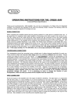
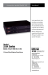
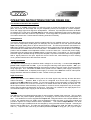
AUDI O
LIMITED
OPERATING INSTRUCTIONS FOR THE CREEK P42
The function of the basic Pre- amplifier
The function of the P42 pre-amplifier is to allow the user to control the signals from various sources
(Disc, CD, Tuner, AV and Tape) and vary the amplitude (volume) of the signal to a Power amplifier,
which will supply higher level signals to loudspeakers. Therefore, a pre-amplifier should be as flexible
as possible and, in this case, the Creek P42 has a wide range of standard functions and is designed to
be configured to meet the customers requirements. Future up-grades are possible as it uses a system
of modular construction. Please read the following instructions carefully.
Getting Started
Unpack the amplifier and keep the packing material safe for any possible future use. Connect one of
your source components (a CD player for example) into the sockets on the rear panel marked CD
Input, using high quality phono to phono interconnect cords. The Pre-amp should be connected to an
A42 power amplifier via a pair of high quality phono to phono interconnect cords plugged into Output 1,
Select CD with the Listen selector on the front panel. The balance control should be set in the middle
position and the volume control adjusted to about 9 o'clock to start with. Connect the power supply,
described below and then press the power switch on the front panel. There will be a 2 - 5 second delay
before the signal is allowed through to the power-amplifier, to prevent unwanted noises being amplified.
With a signal present on the input, adjust the volume control and, while listening to some relaxing
music, please read the rest of this instruction manual.
Power requirements
The P42 is an active pre-amp so therefore needs voltage to run its circuitry. A custom low voltage DC
power cord is supplied with the P42. If you are using the matching Creek power amplifier - A42 - you
should plug one end of the power cord into the matching socket on the rear of each unit and screw the
fixing rings tight. This will enable the P42 to draw power from the A42's power supply. Should you
want to run the P42 alone, a separate power supply or a version of the P42 with a built-in mains power
supply should be used and is available to order. Please consult your dealer.
Input Connection
All the input sockets on the P42 are factory set for line level signals only and they all have the same
relative sensitivity.
However, Aux. 1 input can be configured as a Phono input by plugging in a
suitable Creek MM or MC Phono module. To fit a Phono module it is first necessary to remove the Link
PCB which is fitted to one of the two connectors. Your dealer will be able to advise you about this. As
all the inputs have the same sensitivity it is possible to connect a source component to any of the inputs
without worrying about the description of the input. Tape input 1 & 2 allows for two tape players to be
connected and tape to tape copying in both directions is possible.
Outputs
The P42 pre-amp is equipped with three pairs of output sockets, instead of the usual one. This is to allow
for more than one power amplifier (Bi-amping or Tri-amping) to be connected to the pre-amplifier at a
time. The standard P42 comes supplied with output one configured with an active Output Module, and
2 and 3 are supplied with Link PCB's, that are designed to take the place of the active module and
provide a signal to the output without further amplification. The internal Output Module has three
different levels of gain available and can be changed by moving the slide switch if required. Normally the
switch is set for 6dB's (X 2). The other two gain settings, marked on the PCB, are 9dB and 12dB ( X 3
and X 4 ). Outputs 2 and 3 are set by an internal passive Link PCB for unity gain ( X1 ) input to output.
P42inst1
To increase the gain on these outputs it is necessary to purchase extra active Output Module/s as
required, one per stereo output. Your dealer can advise. To prevent unwanted noises , the active
Output module has a muting circuit that shorts the signal to ground when the pre-amp is switched on
and off. Caution: The outputs that have only Link PCB's fitted do not mute the output on switching-on or
off. A special Bridging module is also available that will allow two power amplifiers to be connected in
bridge mono mode, providing much higher output power.
Tape output is provided on sockets Tape Output 1 and 2 and has a 1KΩ impedance, which is low
enough to drive most machines. As the outputs are electrically buffered it is not possible to load the
normal signal path of the pre-amplifier by using one or two low impedance tape recorders.
Front panel controls
Listen
Record
Balance
Aux 1
Aux 1
CD
CD
Tuner
Tuner
Aux 2
Aux 2
Tape 1
Tape 2
Tape 1
Tape 2
Phones
Volume
Power
P 42 Pre - amplifier
1
2
3
4
5
6
To select a source component you wish to listen to, rotate selector (1) to the desired input. To record
from a source component, rotate selector (2) to the desired input. This two control facility allows you to
listen to a different input from one you may want to record. If you want to record from one tape recorder
to another it is necessary to select the source recorder on (2) and monitor the recording on (1).
Balance (3) and Volume (5) controls alter the amount of signal allowed through the pre-amplifier prior to
being amplified by the Output module. Normally, the (3) should be set with the marker in the vertical
position for equal sound level from each channel. If more or less sound level is required from one
channel, turn the control either way until the desired balance is achieved. The Volume control functions
as an attenuator for the signal, reducing the level from the maximum possible. It does not boost the
signal level.
The Phones socket (4) is inoperative until configured by the dealer. A plug-in module is required to
provide the amplification for headphones. The Phones output has an impedance of 220Ω and the
amplification factor is determined by the impedance of the phones used. Control the level required by the
volume control. When the Phones socket is used the active Output modules will be muted.
TECHNICAL SPECIFICATION
TOTAL HARMONIC DISTORTION
FREQUENCY RESPONSE
LINE INPUTS
TAPE LOOPS
OUTPUTS
TAPE OUTPUTS
GAIN From OUTPUT 2 & 3 with LINK PCB installed
GAIN From OUTPUT 1 switchable
MAXIMUM OUTPUT VOLTAGE per Outut module
OUTPUT IMPEDANCE
SIGNAL TO NOISE RATIO
SEPARATION
POWER CONSUMPTION
POWER REQUIREMENTS
WEIGHT PACKED
SIZE
< 0.01% 20 Hz to 20 kHz
0 Hz to 35 kHz -1dB
X 4 at 47kΩ
X2
X 3 Maximum
X 2 at 1kΩ
X 1 (0dB)
x 2 (6dB), X 3 (9dB) & X 4 (12dB)
6V AT 10kΩ load
1KΩ
-105dB for 600mV output
-80 dB'S at 1 kHz
7W DC (15W AC mains version)
+35 & -35V's DC from A42
3.7 Kgs, 9 lbs
420 X 60 X 230 mm 16.5 X 2.4 X 9''
CREEK AUDIO LTD, 2 BELLEVUE ROAD, FRIERN BARNET, LONDON, N11 3ER, ENGLAND.
Tel: (44) 0 181 361 4133
Fax: (44) 0 181 361 4136
email : [email protected]
P42inst1