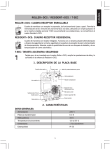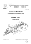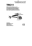
1
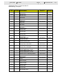
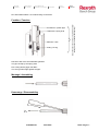
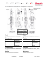
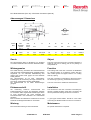
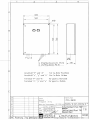
Industrial
Hydraulics
Electric Drives
And Controls
Linear Motion and
Assembly Technologies
Pneumatics
Service
Automation
Mobile
Hydraulics
S
BRUINHOF
MARINE
Siemens Nederland N.V.
P.O. Box 9607, NL-3007 AP ROTTERDAM
Boterdiep 37, NL-3077 AW ROTTERDAM
Tel.
: +31 (0) 10 497 08 08
Fax
: +31 (0) 10 482 43 50
E-mail : [email protected]
Internet : www.bruinhof.nl
Betriebsanleitung / Operating Instructions
Pneumatische Fernbedienungs Anlage
Pneumatic Remote Control Device
4/1675/4000/0
21.04.04
PFA 8600 / 24 V=
Made in Germany
Type / product
PFA
Ausführungs Nr. / design no.
8600
Auftrag Nr. / order no.
Siehe Aufkleber Schranktür
Note lable on the door of the cabinet
4/1646/4000/0
PFA 8600
Mobile Hydraulics
Bosch Rexroth AG
Inhaltsverzeichnis • Table of Contents
Sicherheitshinweise
Notes on Safety
-
4/1675/4001/0
Allgemeine Hinweise
General Remarks
-
4/1675/4002/0
Schaltschema
Control Scheme
-
4/1675/1001/0
Beschreibung + Geräteliste
Description + Parts List
-
4/1675/4003/0
Schalteinheit (Teil 70)
Control Unit (Part 70)
-
3/1675/1002/0
Beschreibung (Teil 70)
Description (Part 70)
-
4/1675/4004/0
Einstellung (Teil 70)
Adjustment (Part 70)
-
4/1675/4005/0
Schalteinheit (Teil 70) - Anordnung
Control Unit (Part 70) - Location
-
3354305100
Schnellanschlüsse
Quick-fixing Connections
-
4/1646/8214/1
Zeichnungen
Drawings
-
4/1093/5533/1
4/1093/5279/3
-
4/1093/5277/3
-
4/1675/5001/0
Ersatzteilbestellung
Spare Part Ordering
-
4/1675/4006/0
Anschriften
Addresses
-
Liste RDE 80 103
2/21
4/1675/4001/0
Mobile Hydraulics
PFA 8600
Bosch Rexroth AG
Sicherheitshinweise • Notes on Safety
1.1 Einführung
1.1 Introduction
In der vorliegenden Betriebsanleitung finden Sie Informationen zum Einbau, zur Inbetriebnahme, zur Pflege
und Wartung und zur Ersatzteilbestellung.
The present operation instructions contain information
on installation, start-up, care and maintenance as well
as spare part ordering.
Beachten Sie unbedingt die Sicherheitshinweise
dieser Dokumententation.
Make sure the safety instructions in this documentation will be carefully observed.
-
-
Allgemeine Sicherheitshinweise finden Sie in
diesem ersten Kapitel.
General notes on safety are listed in this first
chapter.
1.2 Sicherheitshinweise
1.2 Notes on Safety
Die Produkte von BOSCH-REXROTH sind nach dem
aktuellen Stand der Wissenschaft und Technik ausgelegt und hergestellt. Dennoch können Gefahren
auftreten für:
Körper und Gesundheit,
das Produkt und die Gesamtanlage,
sonstige Werte.
All BOSCH-REXROTH products are designed and
manufactured acc. to the state of the art of science and
technology. Nevertheless, it cannot be ruled out danger
may arise to:
Life and limb,
the product and overall plant,
other assets.
Gefahren können insbesonders dann auftreten:
- wenn unzureichend ausgebildetes Personal am
Produkt tätig ist,
- wenn das Produkt unsachgemäß installiert, bedient
und instand gehalten wird,
- wenn das Produkt zu nicht bestimmungsgemäßen
Gebrauch eingesetzt wird.
In particular, hazards may occur:
- if insufficiently trained personnel manipulates the
product,
- if the product is inexpertly installed, operated and
serviced,
- if the product is used for other than the intended
purposes.
Alle Personen, die mit dem Betrieb der Anlage oder
des Produktes befaßt sind, müssen:
- unbedingt das Kapitel „Sicherheitshinweise“ gelesen und verstanden haben,
- diese Betriebsanleitung zumindest in den Teilen
kennen, in denen die jeweilige Tätigkeit und zugehörige Gefahrenhinweise beschrieben sind,
- mit Abschaltprozeduren, z.B. „NOT-AUS“, der ganzen Anlage oder den für die jeweilige Tätigkeit wichtigen Teile der Anlage vertraut sein,
- technisch ausreichend ausgebildet und zu der jeweiligen Tätigkeit befugt sein,
- ihre Aufgaben und Befugnisse kennen.
All persons responsible for the operation of the
plant or product must:
- have definitely read and understood the chapter
„Notes on Safety“,
- know these Operating Instructions or at least be
familiar with those parts where the respective activity
and associated dangers are described,
- be familiar with shut-down procedures, e.g. „Emergency-OFF“, relating to the entire plant or to plant
items important to relevant activity,
- have adequate technical qualifications and be authorized to perform the relevant activity,
- know their specific duties and authority.
Sie müssen unbedingt:
- alle Handlungen unterlassen, die Gefahren für Körper und Gesundheit, Gefahren für das Produkt oder
Gefahren für andere Werte bedeuten könnten,
- alle an dem Produkt vorgenommenen Veränderungen dem zuständigen Vorgesetzten oder Betreiben mitteilen,
- alle Veränderungen beim Betrieb des Produktes,
z.B. unübliche Laufgeräusche, dem zuständigen
Vorgesetzten oder Betreiber mitteilen.
Moreover, it is mandatory that these persons:
- refrain from doing anything that might cause bodily
harm or constitute a danger to health, the product or
other assets,
- inform their superiors in charge or the Operator of
any modifications made to the product,
- inform their superiors in charge or the Operator of
any changes detected in the operational behaviour of
the product, e.g. unusual running noise.
3/21
4/1675/4001/0
Mobile Hydraulics
PFA 8600
Bosch Rexroth AG
Sicherheitshinweise • Notes on Safety
An dem Produkt dürfen keine Veränderungen vorgenommen werden, die nicht zuvor von BOSCHREXROTH genehmigt worden sind.
No modifications to the product are permitted unless the prior approval of BOSCH-REXROTH has
been obtained.
Der Anwender verpflichtet sich:
- am und um das Produkt für Sauberkeit und Ordnung
zu sorgen,
- das Produkt nur in einwandfreiem Zustand zu betreiben,
- das Produkt nur zum bestimmungsgemäßen
Gebrauch einzusetzen,
- umlaufende Teile durch geeignete Schutzvorrichtungen abzusichern,
- das Personal soweit wie nötig zum Tragen von
Schutzkleidung zu verpflichten,
- dem zuständigen Personal diese Betriebsanleitung
auszuhändigen.
The User shall undertake to:
- ensure that the product and ist surroundings are kept
clean and in good order,
- operate the product only when in perfect condition,
Zum bestimmungsgemäßen Gebrauch gehört auch die
Beachtung aller Angaben dieser Betriebsanleitung.
Beachten Sie ergänzend zur Betriebsanleitung alle
allgemein gültigen gesetzlichen und sonstigen Regelungen zur Unfallverhütung.
Using the equipment for the intended purpose as set
out above also includesobserving the instructions given
in this operating manual.
In addition to the procedures and instructions outlined
in this operating manual all generally applicable statutory and other accident prevention rules and provisions
must be observed.
Die Gewährleistung durch BOSCH-REXROTH erlischt:
The warranty obligations of BOSCH-REXROTH will
become void:
-
wenn das Produkt ohne unsere Zustimmung geöffnet oder verändert wird,
bei Nichtbeachtung der Instruktionen dieser Betriebsanleitung,
bei Ein- und Anbau nicht von uns gelieferter oder
genehmigter Ersatzteile und Zusatzgeräte,
-
bei unsachgemäßer Handhabung des Produktes.
-
-
- use the product exclusively for the intended purpose,
- safeguard rotating parts by means of suitable protective systems,
- instruct the personnel to wear protective clothing, to
extent deemed necessary,
- distribute these operating instructions among the
personnel in charge.
-
if the product is opened or modified without our
consent,
in the event the instructions in this manual are disregarded,
if spare parts and auxiliary items are built in or attached which have not been supplied or approved by
us.
if the product is improperly handled or manipulated.
Technische Änderungen, die der Verbesserung des
Produktes dienen, behalten wir uns vor.
We reserve the right to implement technical changes
for product improvement purposes.
Soweit vertraglich nichts anderes vereinbart ist, richten
sich die Gewährleistungsansprüche nach den zum
Zeitpunkt des Vertragsabschlusses geltenden "Allgemeinen Bedingungen für Lieferungen und Leistungen"
von BOSCH-REXROTH.
Unless otherwise stipulated in the contract, any warranty claims shall be dealt with in accordance with
BOSCH-REXROTH´s „General Terms and Conditions
of Supply and Services“ applicable at the time the contract has been concluded.
Urheberrecht
Das Urheberrecht an Zeichnungen verbleibt bei uns.
Eine Zeichnung darf nur zu den Zwecken benutzt werden, zu denen sie dem Empfänger anvertraut ist. Ohne
unsere ausdrückliche schriftliche Genehmigung dürfen
Zeichnungen nicht an Dritte weitergegeben oder diesen
zugänglich gemacht werden. Jede Vervielfältigung auch von Einzelheiten - ist untersagt.
Zuwiderhandlungen werden gerichtlich verfolgt.
Copyright
The copyright on drawings remains with us. A drawing
must only be used for the purposes it has been transfered to the recipient. Drawings must not be handed over
disclosed to third parties without our express consent in
writing.
Any reproduction of a drawing in whole or parts is prohibited.
Contraventions will be prosecuted.
4/21
4/1675/4002/0
PFA 8600
Mobile Hydraulics
Bosch Rexroth AG
Allgemeine Hinweise • General Remarks
1. Ausführung der Fernbedienungsanlagen
1. Desings of Remote
Control Cevices
Die Fernbedienungsanlagen enthalten alle für die
Schaltung und Überwachung der Kupplung erforderlichen Geräte.
The remote control devices comprise all control parts
required for the control and supervision of the clutch.
Die Schalteinheit (Teil 70) ist so ausgeführt, dass ein
automatisches Ausschalten der Kupplung erfolgt, wenn
der Schaltluftdruck unter den für eine schlupffreie
Drehmoment-Übertragung erforderlichen Wert abfällt.
Für jede Kupplung ist eine separate Schalteinheit vorgesehen.
The control unit (part 70) is designed to guarantee an
automatic disengagement of the clutch if the air pressure drops below the value whitch is necessery to achieve
a slipfree torque transmission. For each clutch an individual control unit is provided.
2. Beschreibung
2. Descriptions
Zu jedem Schaltschema gehört eine genaue Beschreibung der gesamten Fernbedienungsanlage.
Each control scheme is furnished with a detailed description of the complete remote control device.
3. Gerätelisten
3. Part Lists
Auf der zu jedem Schaltschema gehörenden Gerätelisten sind alle im Schaltschema enthaltenen Geräte
aufgeführt. Die Abmessung der Geräte sind aus den
angeführten Maßblättern zu ersehen.
All control parts mentioned in control scheme are listed
in a parts list. The dimension of these control parts are
show in the named demension sheets.
4. Lieferumfang
4. Scope of Delivery
Zum BOSCH-REXROTH – Lieferumfang gehören alle
auf dem Schaltschema gezeichneten Geräte mit den
Teile-Nummern 1 bis 99.
Alle Teile, mit Ausnahme der Schalteinheit (Teil 70),
werden als Einzelteile, einschließlich Verschraubungen
und Dichtungen, passend zu den in der Beschreibung
angeführten Rohrleitungen, geliefert. Die Schalteinheit
(Teil 70) ist anschlussfertig in einem Schaltschrank
eingebaut.
The BOSCH-REXROTH - supply covers all control
parts with the part numbers 1 to 99 indicated on the
control scheme.
All parts, with the exception of the control unit (part 70),
are seperately delivered including all pipe fittings and
gaskets suited to the pipes indicated in the description.
The control unit (part 70) is delivered as a completely
mounted unit in a cabinet.
Schalt- und Steuergeräte ab Teil-Nummer 100 gehören nicht zum BOSCH-REXROTH – Lieferumfang.
Control parts with part number 100 and/or more are
not delivered by BOSCH-REXROTH.
5/21
4/1675/4002/0
PFA 8600
Mobile Hydraulics
Bosch Rexroth AG
Allgemeine Hinweise • General Remarks
5. Druckluftversorgung
5. Compressed Air Supply
Wichtigste Voraussetzung für eine sichere Funktion
aller Geräte und der Kupplung ist saubere, trockene
und ölfreie Druckluft.
The indispensable requirement for safe operation of all
control parts and the clutch is a clean, dry, and oil-free
compressed air.
Wir empfehlen, außer dem Hochdruckfilter in der
Druckluftversorgungsstation, weitere Leitungsfilter an
verschiedenen Stellen im pneumatischen Steuerungssystem anzuordern.
We recommed the installment of additional air filters at
different points of the system beside the obligantory
highpressure filters in the main supply line.
Druckluftöler sollen nicht vorgesehen werden, da diese
im Laufe der Zeit zu einer Verölung der Schaltgeräte
des Schaltzylinders der Kupplung führen. Die Schmierung der Schaltgeräte-Innenteile, die bei der Montage
im Herstellwerk vorgenommen wird, ist innerhalb der
für die gesamte Anlage vorgesehenen Wartungszeiträume vollkommen ausreichend.
Compressed air lubricators should not be installed:
these devices will produce faults for the control parts
and the clutch cylinder by the oil mud. The lubrication
of the internal part of the control parts, done by the
makers during assembling, is fully sufficient for the
maintenance period which is necessary for the overall
installation.
Ein Lufttrockner ist in jedem Fall zu empfehlen, da die
an den Filter und Luftbehältern vorgesehenen Entwässerungsventile in der Regel nicht ausreichen. Ob Frostschützer vorzusehen sind, hängt von den jeweiligen
Einbauverhältnissen ab und muss von Fall zu Fall vom
Betreiber der Fernbedienungsanlage überprüft werden.
An air-drier must be installed in any case. The drainvalves on the filters and compressed air receivers are
normally not sufficient. The requirement of anti-freezig
apparatuses depends on the recpective installation
conditions and must be checked in each case by the
user of the remote control device.
Für eine ausreichende Dimensionierung der DruckluftAnlage ist zu sorgen. Der Luftverbrauch für jeden Einschaltvorgang setzt sich zusammen aus dem Volumen
des Kupplungs-Schaltzylinders (je nach Kupplungsgröße 1 bis 80 Liter) und dem zu füllenden Volumen der
Steuergeräte und Rohrleistungen selbst. Für die
Schalteinheit (Teil 70) beträgt der Luftverbrauch ca. 1,5
Liter pro Einschaltvorgang. Eine betriebssichere
Schaltung der Kupplung ist gewährleistet, wenn am
Anschluss „P“ der Schalteinheit (Teil 70) ein Luftdruck
von 10 -0,5 bar zur Verfügung seht.
A sufficient dimensioned compressed air plant must be
provided. The air consumption for each engagement is
composed of the volume of the clutch cylinder (1 to 80
litres depending on clutch size) and the volume of the
pneumatic system which must be filled up. The air
consumption of the control unit (part 70) is 1.5 litres per
angagement. A reliable clutching is ensured with an air
pressure of 10 -0,5 bar to connection „P“ of the control
unit (part 70).
Vor dem Anschluss „P“ der Schalteinheit (Teil 70), und
zwar so nahe wie möglich, muss ein Luftbehälter eingebaut werden, damit beim Einschalten der Kupplung
genügend Druckluft zur Verfügung steht. Die Größe
dieses Behälters muss etwa der 10-fachen Menge der
Kupplungsfüllung entsprechen.
A compressed air reciver of the at least 10-fold volume
of the clutch cylinder must be installed as near as possible before connection „p“ of the control unit (part 70)
to have sufficient compressed air during engagement
6/21
4/1675/4002/0
Mobile Hydraulics
PFA 8600
Bosch Rexroth AG
Allgemeine Hinweise • General Remarks
PNEUMAFLEX KA
PNEUMASTAR KU
Kupplungsgröße
Luftverbrauch je
Einschaltung
Luftbehältergröße
Kupplungsgröße
Luftverbrauch je
Einschaltung
Luftbehältergröße
clutch size
Air consumption per
engaging operation
Capacity of
air receiver
clutch size
Air consumption per
engaging operation
Capacity of
air receiver
VLmin 1)
VLmax 1)
dm
3
VB 2)
dm
VLmin 1)
3
VLmax 1)
dm
3
VB 2)
dm
3
KA 100
KA 110
KA 140
0,3
0,4
0,8
0,8
1,0
1,8
-
KU 120
KU 130
KU 140
0,7
0,9
1,1
1,7
2,0
2,5
-
KA 160
KA 180
KA 200
0,9
1,0
1,3
2,8
3,4
4,0
-
KU 150
KU 160
KU 180
1,2
1,6
1,9
2,8
3,6
4,2
-
KA 220
KA 240
KA 260
2,0
2,5
3,0
5,3
6,3
7,5
-
KU 200
KU 220
KU 240
2,5
3,0
3,9
5,2
6,2
10,3
40
KA 280
KA 300
KA 320
3,5
5,0
6,0
8,9
14
16
35
50
60
KU 260
KU 280
KU 330
4,9
5,8
7,2
12,4
14,0
16,8
50
60
80
KA 340
KA 360
KA 380
8,2
10
14
21
26
33
80
100
140
KU 350
KU 370
KU 390
8,5
11,1
12,7
20,0
25,0
27,7
100
120
140
KA 390
KA 410
KA 430
18
21
26
38
46
69
180
200
250
KU 410
KU 430
KU 450
16,2
20,1
26,5
34,3
52,0
64,4
160
200
250
KU 470
KU 490
KU 510
31,8
50,0
52,5
75,3
100
115
300
500
500
KU 530
KU 550
KU 570
67,0
78
100
134
150
200
750
750
1000
1)
Werte gelten für komprimierte Luft und für das
Volumen des Schaltzylinders in der Kupplung. Für
externe Rohrleitungen und Schaltgeräte sind entsprechende Zuschläge zu berücksichtigen. Die
Maximalwerte werden erreicht bei maximalen Verschleiß der Reibbeläge.
1) Values relate to compressed air and are based on
the clutch cylinder volume. External pipework and
actuating devices make appropriate allowances
necessary. The maximum figures indicated are
reached at maximum friction lining wear.
2)
Bei Mehrmotoren-Anlagen kann für zwei Kupplungen ein gemeinsamer Luftbehälter vorgesehen
werden, wenn die Luftbehältergröße um 50% erhöht
wird.
2) In case of multi-engine installations a common air
receiver may be employed for two clutches provided
that the receiver capacity is increased by 50%.
7/21
4/1675/4002/0
PFA 8600
Mobile Hydraulics
Bosch Rexroth AG
Allgemeine Hinweise • General Remarks
6. Verblockung
6. Interlocks
Die Schalteinheit (Teil 70) ist serienmäßig mit zwei
Magnetventilen (70.16 + 70.17) zum Anschluss an
Verblockung aller Art ausgerüstet. Beim Anschluss von
Verblockung sind jedoch die Vorschriften der Klassifikationsgesellschaft zu beachten.
The control unit (part 70) is equiped with two magnetvalves (70.16 + 70.17) for the connection of interlocks
of all kind. For the installation of interlock devices the
classification rules must be noted.
Ferner ist die Schalteinheit (Teil 70) mit einer HandNotschaltung („EIN – AUS“) ausgerüstet, die gegenüber der Fernbetätigung bevorrechtigt wirkt und auch
die oben genannten Magnetventile umgeht. Bei Betrieb
der Kupplung über diese Hand-Notschaltung wird jedoch der Schaltluftdruck nicht überwacht.
Moreover, the control unit (part 70) is equiped with an
emergency-handle („IN – OUT“) which is working privileged opposite the remote control and which by-passes
above mentioned magnet-valves. If the clutch is working by this emergency-handle the air pressure is not
supervised.
8/21
4/1675/4003/0
Mobile Hydraulics
PFA 8600
Bosch Rexroth AG
Beschreibung • Description
1. Art der Fernbedienungs
anlage
1. Type of Remote control
Device
Das Schaltschema Ausführungs-Nr. 8600 zeigt die
Schaltung einer Kupplung. Die Schaltung erfolgt
elektro-pneumatisch von einem Fahrstand.
The control scheme od design No. 8600 shows the
control of one clutch. The controlling is done electropneumatically from one station.
2. Rohrleitungen und
Anschlüsse
2. Pipe system and
Terminals
Hauptluft, Cu-Rohr 15 x 1,5 mm
Anschluss: A; P
---------___________
Steuerluft, Cu-Rohr 8 x 1 mm
Anschluss: x; y; z
Stromnetz
Main air, Pipe 15x1,5mm
Terminal: A; P
---------___________
Pipe : Cu 8 x 1 mm
Terminal: x; y; z
Electric network
Luftdruck für Anschluss „P“ : 10 – 0,5 bar
Air pressure for terminal „P“ : 10 – 0,5 bar.
3. Funktionsbeschreibung
3. Principles of Operation
3.1
3.1
Das Einschalten der Kupplung erfolgt durch
Betätigung von Taster (101). Hierdurch wird
Spule „14“ von Ventil (1) erregt, so daß ein
Steuerluft-Impuls zum Anschluss „z“ der Schalteinheit (70) gelangt und diese auf Durchgang
schaltet. Hauptluft strömt nun über Schlauchleitung (61) und Rotoranschluss (62) in die
Kupplung und schaltet diese ein.
The engagement of the clutch takes place by
actuation of push-button (101). Hereby the
magnet „14“ of vale (1) is engergized, so that a
control air impulse comes to connection „z“ of
the control unit (70) and changes it over on
passage. Now the main air flows over flexible
hoseline (61) and rotor conection (62) into the
clutch and engages it.
Funktion der Schalteinheit (70) siehe Zeichnung
Nr. 3/1675/1002/.. und 4/1675/4004/..
For function of control unit (70) see drawing No.
3/1675/1002/.. and 4/1675/4004/..
Der Schaltzustand der Kupplung wird durch die
Meldelampen (103+104) angezeigt
The position of the clutch is indicated by signal
lamps (103+104).
Luftbehälter (100) garantiert, daß beim Einschalten genügend Druckluft zur Verfügung
steht.
Air receiver (100) guarantees to have sufficient
compressed air for engagement of the clutch.
3.2
Das Ausschalten der Kupplung kann erfolgen:
3.2
The disengagement of the clutch can be effected :
3.21
Durch Betätigung der Taster (102). Hier durch
wird Spule „12“ von Ventil (1) erregt, so dass ein
Steuerluft-Impuls zum Anschluss „y“ der Schalteinheit (70) gelangt.
3.21
By actuation of push-button (102). Hereby the
magnet „12“ of vale (1) is energized, so that a
control air impulse comes to connection „y“ of
control unit (70).
3.22
Automatisch bei zu niedrigem Schaltluftdruck
durch die Schalteinheit (70).
3.22
Automatically at low air pressure by the control
unit (70).
3.23
Bei Ansprechen der Verblockungskontakte (105
und/oder 106).
3.23
If interlocks contacts (105 and/or 106) are closed.
3.24
Bei Ausfall der Druckluftversorgung.
3.24
By a breakdown in the compressed air supply.
9/21
4/1675/4003/0
PFA 8600
Mobile Hydraulics
Bosch Rexroth AG
Beschreibung • Description
4. Montage
4. Installation
Beim Einbau des Ventiles (1) ist die auf dem Maßblatt
angegebene Einbauvorschrift zu beachten.
When mounting the valve (1) the mouting instruction on
the dimension sheet must be observed.
10/21
4/1675/4003/0
PFA 8600
Mobile Hydraulics
Bosch Rexroth AG
Geräteliste • Parts List
1. Lieferung durch BOSCH-REXROTH
Delivered by BOSCH-REXROTH
Teil-Nr
Part-No.
Stück
Quantily
Bennennung
Denomination
1
1
5/3-Wege-Magnetventil
5/3-way-magnet-vale
Bestell-Nr. Maßblatt
Order No. Dimension
sheets
Hersteller, Bemerkung
Producer Remarks
Bosch
16434288
4/1093/5533/1
Bosch-Rexroth
Zur Verbindung Rohr mit 5/3-WegeMagnetventil
Bosch-Rexroth
For connection pipe with 5/3-waymagnat-vale
2
5
Verschraubung
Pipe fitting
16190037
S GEV 8 LR W
61
1
Schlauchleitung
Flexible hoseline
R15-1/2“ NPTx300
16438281
4/1093/5279/3
62
1
Rotoranschluss
Rotor connection
C2
16434153
4/1093/5277/3
Fawick
70
1
Schalteinheit (Teil 70)
Conrol unit (part 70)
16572399
3/1675/1002/0
4/1675/5001/0
Bosch-Rexroth
Bosch-Rexroth
2. Lieferung nicht durch BOSCH-REXROTH
Not delivered by BOSCH-REXROTH
Teil-Nr.
Part-No.
Stück
Quantity
Bennenung
Denomination
Zweck
Intended use
100
1
Luftbehälter
Air receiver
Pufferbehälter. Größe ist abhängig von Kupplungsgröße.
Buffer receiver. Capacity depends on clutch size
101
1
Taster
Push-button
für „KUPPLUNG EIN“
for „CLUTCH IN“
102
1
Taster
Push-button
für „KUPPLUNG AUS“
for „CLUTCH OUT“
103
1
Meldelampe
Signal lamp
für „KUPPLUNG EIN“
for „CLUTCH IN“
104
1
Meldelampe
Signal lamp
für „KUPPLUNG AUS“
for „CLUTCH OUT“
105
1
106
1
Verblockungskontakt
Interlock contact
Verblockungskontakt
Interlock contact
„KUPPLUNG AUS“
wenn geschlossen
„CLUTCH OUT“
if closed
11/21
4/1675/4004/0
PFA 8600
Mobile Hydraulics
Bosch Rexroth AG
Schalteinheit Teil 70 • Control Unit Part 70
Beschreibung • Discription
1. Aufgabe der Schalteinheit
1. Purpose of Control Unit
Die Schalteinheit – Hauptbestandteil jeder Fernbedienungsanlage ist so ausgeführt, dass ein betriebssicheres Schalten der Kupplung gewährleistet ist. Sie ist für
alle pneumatisch schaltbaren BOSCH-REXROTH Kupplungen geeignet.
The control unit – main part of each remote control
device – is designed to guarantee a reliable engaging
of the clutch. It is suitable for all pneumatically operated
BOSCH-REXROTH - clutches.
Das Einschalten von der Kupplung erfolgt mit einem
hohen, am Anschluss „P“ anliegenden Einschaltluftdruck, der nach ca. 30 sec. Automatisch auf den jeweils erforderlichen Betriebsluftdruck reduziert wird.
The engagemment of the clutch takes place with a high
engaging air pressure connected to terminal „P“, which
is reduced automatically to the necessary working air
pressure after abt. 30 sec.
Abhängig von der Kupplungstype oder den vorliegenden Betriebsbedingungen kann Einschalt- und Arbeitsluftdruck gleich sein.
Depending on clutch type or present working conditions
the engaging air pressure and working air pressure can
have the same value.
Unterschreitet der Luftdruck einen Mindestwert, so
erfolgt ein automatisches Ausschalten der Kupplung
bzw. die Kupplung kann nicht eingeschaltet werden.
If the air pressure drops below a set value, the clutch
will be disengaged automatically resp. an engagement
of the clutch is not possible.
Jede Schalteinheit ist vor Auslieferung entsprechend
Kupplungstype und Betriebsbedingungen eingestellt.
Each control unit is specially adjusted for clutch type
and working conditions before delivery.
Auf einem auf der Innenseite der Schranktür angebrachten Aufkleber sind alle Einstelldaten vermerkt.
On a lable located on the inner side of the door of
the cabinet all date about adjustment are noted.
2. Anschlüsse
2. Terminals
Anschluss P:
Terminal P:
Anschluss A:
Anschluss X:
Anschluss Y:
Anschluss Z:
Klemme 1/2
Klemme 3/4
Klemme 5/6
Klemme 5/7
Klemme 8/9
Klemme 8/10
Hauptluft mit10-0,5 bar
Cu-Rohr 15x1,5 mm
Zur Kupplung
Cu-Rohr 15x1,5 mm
Steuerluft-Versorgung für externe
Geräte.
CU Rohr 8x1 mm
Steuerluft-Impuls für „KUPPLUNG
AUS“ mit 5...10 bar.
Cu Rohr 8x1mm
Steuerluft-Impuls für „KUPPLUNG
EIN“ mit 5...10bar.
Cu Rohr 8x1mm
Stromanschluss für Magnetventil
(70.17)
Stromanschluss für Magnetventil
(70.16)
Anschluss für Meldelampe
„KUPPLUNG EIN“
Anschluss für Meldelampe
„KUPPLUNG AUS“
Alarmkreise
„LUFTDRUCKMANGEL“
Terminal 1/2
Main air with 10-0,5 bar
Pipe Cu 15x1,5 mm
To the clutch
Pipe Cu 15x1,5 mm
Control air supply for external control
Parts.
Pipe CU 8x1 mm
Control air impulse for „CLUTCH
OUT“ with 5...10 bar.
Pipe Cu 8x1mm
Control air impulse for „CLUTCH IN“
with 5...10bar.
Pipe Cu 8x1mm
Circuit for magnet-valve (70.17)
Terminal 3/4
Circuit for magnet-valve (70.16)
Terminal 5/6
Circuit for signal lamp
„CLUTCH IN“
Circuit for signal lamp
„CLUTCH OUT“
Alarm circuit
„AIR PRESSURE FAILURE“
Terminal A:
Terminal X:
Terminal Y:
Terminal Z:
Terminal 5/7
Terminal 8/10
12/21
4/1675/4004/0
Mobile Hydraulics
PFA 8600
Bosch Rexroth AG
Schalteinheit Teil 70 • Control Unit Part 70
Beschreibung • Discription
3. Interne Leitungen
3. Internal Pipes
Hauptluft, Cu-Rohr 15 x 1,5 mm
----------
Steuerluft, Kunststoffrohr (Polyamid
11) 4 x 1 mm bzw. metallumflochtener Niederdruckschlauch NW 6.
Main air, Pipe Cu 15x1,5mm
----------
Control air. Pipe: Plastics (Polyamis
11) 4 x 1 mm, resp. low pressure
hoseline with metallic coating 6 mm
nominal width.
4. Funktionsbeschreibung
4. Principles of Operation
Ist Anschluss „P“ ausreichend belüftet und Ventil
(70.01) auf Durchgang geschaltet, so schaltet Ventil
(70.15) um, und zwar durch Steuerluft über Ventil
(70.08). Ventil (70.10) schaltet nun ebenfalls um, und
zwar durch Steuerluft über Ventile (70.16 und 70.17).
If terminal „P“ is pressurized sufficient and valve
(70.01) is opened, valve (70.15) changes over, and that
by control air comming over valve (70.08). Now valve
(70.10) changes over, too, and that by control air comming over valves (70.16 and 70.17).
Manometer (70.06) zeigt den am Anschluss „P“ anliegenden Druck an.
Manometer (70.06) shows the air pressure connected
to terminal „P“.
Druckwächter (70.18) gibt Alarm bei Luftdruckmangel.
Pressurestat (70.18) gives alarm if the air pressure
drops.
Filter (70.02) ist mit einer auswaschbaren FilterPatrone 5...10 µm versehen.
Filter (07.02) is provided with a filter cartridge 5...10
µm, which can be washed out.
In der Druckluft noch vorhandenes Kondenswasser
wird durch den automatischen Kondensableiter (70.03)
nach außen abgelassen.
Condensed water, wich is still in the compressed air, is
drained by automatic drain device (70.03) to the outside of the cabinet.
4.1
4.1
Das Einschalten der Kupplung erfolgt durch
einen Steuer-Impuls auf Anschluss „z“, wodurch
Ventil (70.08) umschaltet. Steuerluft strömt nun
über Ventile (70.09, 70.10 und 70.11) zu Anschluss „4“ von Relaisventil (70.05) und schaltet
dieses auf Durchgang. Damit gelangt die am
Anschluss „P“ anliegende Hauptluft zum Anschluss „A“.
The engagement of th clutch takes place by a
Control air impulse to terminal „z“, whereby
valve (70.08) changes over. Now control air
flows over vales (70.09, 70.10 and 70.11) to
terminal „4“ of relay valve (70.05) and changes it
over on passage. Now the main air connected to
terminal „P“ comes to terminal „A“.
Gleichzeitig wird auch Anschluss „x“ von Zeitventil (70.12) belüftet, das verzögert umschaltet,
so dass auch Ventil (70.09) umschaltet. Anschluss „4“ des Relaisventil (70.05), und somit
Anschluss „A“, wird nun mit dem am Druckminderventil (70.13) eingestellten Betriebsluftdruck
belüftet.
At the same time connection „x“ of valve (70.12)
is pressurized also, which changes over delayed, so that valve (70.09) changes over, too:
terminal „4“ of relay valve (70.05), and with this
terminal „A“, is now pressurized with the working
air pressure set by the pressure reducing valve
(70.13).
Mit Ventil (70.04) wird die Kupplungseinschaltzeit reguliert.
With valve (70.04) the clutch engaging time can
be adjusted.
Manometer (70.07) zeigt den Anschluss „A“, und
somit in der Kupplung anliegenden Luftdruck an.
Manometer (70.07) shows the air pressure of
terminal „A“, which is identical with the air pressure in the clutch.
Über Druckwächter (70.19) kann der Schaltzustand der Kupplung an Meldelampen (Klemmen
5/6 bzw. 5/7) angezeigt werden.
Via pressurestat (70.19) the position of the
clutch may be indicated by signal lamps (terminals 5/6 resp. 5/7).
13/21
4/1675/4004/0
Mobile Hydraulics
PFA 8600
Bosch Rexroth AG
Schalteinheit Teil 70 • Control Unit Part 70
Beschreibung • Discription
4.2
Das Ausschalten der Kupplung erfolgt durch
einen Steuerluft-Impuls auf Anschluss „y“, wodurch der gesamte Steuerkreis über Ventil
(70.08) entlüftet wird. Anschluss „A“ wird somit
über Anschluss „3“ von Relaisventil (70.05)
entlüftet.
4.2
The disengagement of the clutch takes place by
a control air impulse to terminal „y“, whereby the
whole control air circuit is vented over valve
(70,08). Therefore terminal „A“ is also vented
over terminal „3“ of relay valve (70.05).
4.3
Luftdrucküberwachung erfolgt durch Ventil
(70.15), und zwar wird bei ausgeschalteter
Kupplung der vor dem Relaisventil (70.05) anliegende Luftdruck überwacht.
4.3
Supervision of air pressure is done by valve
(70.15). With disenaged clutch the air pressure
before relay valve (70.05) is supervised.
Beim Einschalten der Kupplung wird mit dem
Umschalten von Ventil (70.19) der hinter dem
Relaisventil (70.05) anliegende Luftdruck überwacht.
With engaged clutch and after changing over
valve (70.09) the air pressure behind relay valve
(70.05) is supervised.
Fällt der Luftdruck unter den am Ventil (70.15)
eingestellten Wert ab, so schließt Ventil (70.15)
und entlüftet den Anschluss „14“ von Ventil
(70.10): Anschluss „4“ von Relaisventil (70.05)
wird über Ventil (70.10) entlüftet, so dass:
If the air presure drops below the set value on
valve (70.15), valve (70.15) closes and connection „14“ of valve (70.10) is vented: terminal „4“
of relay valve (70.05) is vented over valve
(70.10), so that:
4.3.1 eine eingeschaltete Kupplung automatisch ausgeschaltet wird.
4.3.1 an engaged clutch is disengaged automatically.
4.3.2 ein Einschalten der Kupplung nicht möglich ist,
da die über Ventil (70.08) kommende Steuerluft
dann über Ventile (70.09 und 70.10) den Anschluss „y“ von Ventil (70.10) belüftet.
4.3.2 an engagement of the clutch is not possible,
because the control air comming over valve
(70.08) flows over valves (70.09 and 70.10) to
connection „y“ of valve (70.10) now.
Ein selbstständiges Wiedereinschalten nach Luftdruckabfall ist ausgeschlossen. Erst durch einen SteuerluftImpuls an Anschluss „y“, wodurch der gesamte Steuerkreis über Ventil (70.08) entlüftet wird, kann erneut
eingeschaltet werden.
An automatic re-engagement after an air pressure drop
is not possible. The clutch can be re-engaged only after
a control air impulse to terminal „y“, whereby the whole
control air circuit is vented over valve (70.08).
4.4
4.4
Verblockungen aller Art können an die / den
Magnetventile (70.16 und 70.17) angeschlossen
werden. Spricht eines dieser beiden Magnetventile an, so wird Anschluss „14“ von Ventil
(70.10) entlüftet, was einem Luftabfall entspricht.
Beim Anschluss von Verblockungen sind die
Vorschriften der Klassifikationsgesellschaft zu
beachten.
4.5
In Notfällen kann die Einschaltung der Kupplung
durch Betätigung von Ventil (70.14) erfolgen.
Hierdurch schaltet Ventil (70.11) um und Anschluss „4“ des Relaisventils (70.05) wird belüftet
Achtung:
a)
b)
c)
Bei Betrieb der Kupplung über Ventil
(70.14) ist zu beachten:
Der Einschalt-Luftdruck wird nicht reduziert.
Der Luftdruck wird nicht überwacht.
Das Ansprechen der Magnetventile (70.16 und
70.17) bleibt wirkungslos.
Interlocks of all kind can be connected to the
magnet valves (70.16 and 70.17). If one of these
magnet-valves is energized, connection „14“ of
valve (70.10) will be vented at once. That mans
the same as an air pressure drop.
For the installation of interlock deviced the classification rules must be noticed.
4.5
In case of emergency an engagement of the
clutch is possible by actuation of valve (70.14).
At this valve (70.11) changes over and terminal
„4“ of valve (70.05) is pressurized.
Attention:
a)
b)
c)
If clutch is working over vale (70.14) it
must be observed:
The engaging air pressure is not reduced.
The air pressure is not supervised.
The interlocks connected to the magnet valves
(70.16 and 70.17) are ot effective.
14/21
4/1675/4004/0
Mobile Hydraulics
PFA 8600
Bosch Rexroth AG
Schalteinheit Teil 70 • Control Unit Part 70
Beschreibung • Discription
5. Einstellung
5. Einstellung
Auf einem auf der Innenseite der Schranktür angebrachten Aufkleber sind alle Einstelldaten vermerkt.
On a lable located on the inner side of the door of
the cabinet all adjustment data are noted.
5.1
Der Einschalt-Luftdruck ist identisch mit dem
Anschluss „P“ anliegenden Luftdruck.
5.1
The engaging air pressure is identical with the
air pressure connected to terminal „P“.
5.2
Der Arbeitsluftdruck wird nach dem Umschalten
von Ventil (70.09) am Druck-Minderventil
(70.13) eingestellt.
5.2
Working air pressure can be set after changing
over of valve (70.09) by pressure reducing valve
(70.13).
5.3
Der Schaltpunkt für automatisches Aus
schalten
bei
Ventil
(70.15)
eingestellt.
Einstellbereich: 0,6 ... 10 bar.
5.3
Auto-disengagement air pressure can be set by
valve (70.15).
Setting range: 0,6 ... 10 bar.
5.4
Die Einschaltzeit der Kupplung wird an Ventil
(70.04) eingestellt.
5.4
Clutch engaging time can be set by valve
(70.04).
5.5
Die Umschaltzeit auf Betriebs-Luftdruck wird an
Ventil (70.12) eingestellt.
5.5
Timing for change-over to working air pressure
can be set by valve (70.12).
5.6
Der Schaltpunkt für Alarmangabe bei Luftdruckabfall wird an Druckwächter (70.18) eingestellt.
Einstellbereich: 0,5 ... 11 bar.
5.6
Switch point for alarm at an air pressure drop
can be set by pressurestat (70.18).
Setting range: 0,5 ... 11 bar.
6. Montage
6. Installation
Sämtliche Schaltgeräte der Schalteinheit (Teil 70) sind
in einem Schaltschrank anschlussfertig eingebaut.
All components of the control unit (Part 70) are mounted and pipe connected in a cabinet.
Die Schalteinheit muss örtlich so eingebaut werden,
dass die Länge der Rohrleitung zwischen Anschluss
„A“
und
der
Kupplung
nicht
mehr
als
5 m beträgt.
The control unit must installed local, so that the length
to the pipe between terminal „A“ and the clutch does
not exceed 5 m.
15/21
4/1675/4004
/
PFA 8600
Mobile
d l
Bosch Rexroth AG
Schalteinheit Teil 70 • Control Unit Part 70
Beschreibung • Discription
Teil
Part
Stück Benennung
Quantity Denomination
Bestell-Nr.
Order No.
Hersteller
Producer
Absperrhahn
Shut-off valve
Filter 30 F 24-1
Filter 30 F 24-1
Kondensatabscheider
Drain device
Drosselventil
Throttle valve
Relaisventil
Relay valve
Manometer
Manometer
Manometer
Manometer
5/2-Wege-Ventil
5/2-way-valve
5/2-Wege-Ventil
5/2-way-valve
7N1.407.001
Bosch
7N1.407.002
Bosch
7N1.407.003
Bosch
7N1.407.004
Bosch
7N1.407.005
Bosch
7N1.407.006
Wika
7N1.407.006
Wika
001.344.467
Bosch
001.344.590
Bosch
5/2-Wege-Ventil
5/2-way-valve
5/2-Wege-Ventil
5/2-way-valve
3/2-Wege-Zeit-Ventil
3/2-way-time-valve
Druckminderventil
Pressure reducing valve
3/2-Wege-Ventil + Rot Drucktaster
3/2-way-valve + Red button
001.344.592
Bosch
001.344.590
Bosch
7N1.407.012
Bosch
7N1.407.013
Bosch
7N1.407.014 +
7N1.417.014
Bosch
7N1.407.015 +
7N1.417.015
Mecman
7N1.407.016
Bosch
7N1.407.016
Bosch
7N1.407.018 +
7N1.417.018
7N1.407.019
Klöckner
7N1.407.020
Bosch
7N1.407.021
Bosch
7N1.407.021
Bosch
001.344.590
Bosch
001.344.590
Bosch
000.725.718
Bosch
70.01
1
70.02
1
70.03
1
70.04
1
70.05
1
70.06
1
70.07
1
70.08
1
70.09
1
70.10
1
70.11
1
70.12
1
70.13
1
70.14
1
70.15
1
3/2-Wege-Ventil + Anschlußplatte
3/2-way-valve + Base plate
70.16
1
70.17
1
70.18
1
70.19
1
70.20
1
70.21
1
70.22
1
70.23
1
70.24
1
70.25
1
3/2-Wege-Magnet-Ventil ; 24 V =
3/2-way-magnet-valve ; 24 V DC
3/2-Wege-Magnet-Ventil ; 24 V =
3/2-way-magnet-valve ; 24 V DC
Druckwächter + Wandbefestigungswinkel
Pressure control + Wall fixing bracket
Druckschalter
Pressure switch
Abströmdüse
Nozzle
Verteilerplatte
Distributor plate
Verteilerplatte
Distributor Plate
5/2-Wege-Ventil
5/2-way-valve
5/2-Wege-Ventil
5/2-way-valve
Rückschlagventil
Back-pressure valve
Bosch
1/2
4/1675/4004
.
PFA 8600
Mobile
.
Bosch Rexroth AG
Schalteinheit Teil 70 • Control Unit Part 70
Beschreibung • Discription
Teil
Part
Stück Benennung
Quantity Denomination
70.26
1
70.27
1
70.28
1
70.29
1
70.30
1
70.31
1
Rückschlagventil
Back-pressure valve
Rückschlagventil
Back-pressure valve
Rückschlagventil
Back-pressure valve
Abströmdüse
Nozzle
Einschraubdrossel
Throttle
Einschraubdrossel
Throttle
Bronze Filterelement 70.02
Bronze filter cartridge 70.02
Ventilplatte (Inkl. 70.08 – 70.24)
Swiveling panel (Incl. 70.08 – 70.24)
Schalteinheit Teil 70 PFA 8600 komplett
Control Unit Part 70 complete
Bestell-Nr.
Order No.
Hersteller
Producer
000.725.718
Bosch
000.725.718
Bosch
000.725.718
Bosch
7N1.407.020
Bosch
001.372.47
Bosch
001.372.4
Bosch
7N1.407.039
Bosch
7N1.407.000
7N6.572.399
Leistungsaufnahme der Magnetventile 70.16 und 70.17: = 8 W
Zulässige Kontaktbelastung für Druckwächter bzw. Druckschalter 70.18 und 70.19: = 2 A.
Power consumption for magnet valves 70.16 and 70.17: = 8 W
Permitted contact loading for pressure control resp. pressure switch 70.18 und 70.19: = 2 A
2/2
4/1675/4005/0
Mobile Hydraulics
PFA 8600
Bosch Rexroth AG
Einstellung • Adjustment
Die Schalteinheit (70) wird grundsätzlich vor der Auslieferung entsprechend Kupplungstype und Betriebsbedingungen eingestellt.
Auf einem auf der Innenseite der Schranktür angebrachten Aufkleber sind alle Einstelldaten vermerkt.
The control unit (70) is adjusted on rinciple for clutch
type and working conditions before delivery.
On a lable located on the inner side of the door of the
cabinet all data about adjustment are noted.
Sollte die Schalteinheit (70) aus irgendwelchen Gründen teilweise oder total verstellt sein, so ist die NeuEinstellung bei Stillstand der Kupplung wie folgt durchzuführen:
If for any reason the control unit (70) is partly or totally
de-adjusted, the re-adjusted has to be done with standstill of the clutch as follows:
1. Vorbereitung
1. Preparing
1.1
Drosselventil (70.04)
Kontermutter lösen, Drosselschraube von der
Hand ohne Kraftaufwand ganz einschrauben.
1.1
Throttle valve (70.04)
Loosen the lock-nut and screw in the throttle
screw totally by hand without any force.
1.2
3/2-Wege-Ventil (70.15).
Kontermutter lösen, Stellschraube soweit herausdrehen, bis die innere Feder spürbar entlastet ist.
1.2
2/3-way-valve (70.15)
Loosen the lock-nut and screw out the adjustment screw until the inner spring is perceptibly de-loaded.
1.3
Druckminderventil (70.13)
Kontermutter lösen, Handrad ohne Kraftaufwand
ganz einschrauben.
1.3
Pressure reducing valve (70.13)
Loosen reducing the lock-nut and screw in the
adjustment screw totally without any force.
1.4
3/2-Wege-Magnetventil (70.16+70.17).
Winkelstecker an der Magnet-Spule lösen und
abziehen.
1.4
3/4-way-magnet-valves (70.16+70.17).
Remove angle plugs on magnet coil.
2. Einschaltzeit der Kupplung
1. Timing for Engagement
2.1
Kupplung mit Not-Schalter (70.14) einschalten,
Drosselschraube des Drosselventils (70.04)
langsam herausdrehen und dabei den zeitlichen
Druckaufbau am Manometer (70.07) beobachten.
2.1
Engage the clutch via emergency-switch (70.14)
and screw out slowly the throttle screw of the
throttle valve (70.04). At this observe the temporal pressure rise on manometer (70.07).
2.2
Vorgang so oft wiederholen, bis der Druckaufbau in der vorgeschriebenen Zeit erfolgt.
2.2
Repeat this progress until the pressure rise
takes place within the stated time.
2.3
Kontermutter von Drosselventil (70.04) anziehen
und Not-Schalter (70.04) in Stellung „OUT“
stellen.
2.3
Fasten the lock-nut of throttle valve (70.04) and
bring emergency-switch (70.14) to „OUT“position.
3. Umschaltzeit auf Arbeitsluftdruck
3. Timing for Change-Over
to Working Air Pressure
3.1
3.1
Die vorgeschriebene Umschaltzeit auf Arbeitsluftdruck ist mit Hilfe des zentralen Drehkopfes
des Zeit-Ventils (70.12) einzustellen.
Set the stated time for change-over to working
air pressure by means of the central rotary knob
of time-valve (70.12).
18/21
4/1675/4005/0
Mobile Hydraulics
PFA 8600
Bosch Rexroth AG
Einstellung • Adjustment
4. Schaltpunkt für autom.
Ausschalten bei Luftdruckmangel
4. Switch Point for AutoDisengagement at low Air
Pressure
4.1
Kupplung durch einen Luft-Impuls auf Anschluss
„z“ der Schalteinheit (70) einschalten und warten, bis die am Zeit-Ventil (70.12) eingestellte
Zeit abgelaufen ist.
4.1
Engage the clutch by an air-impulse to connection „z“ of control unit (70) and wait until the time
set on time-valve (70.12) has run down.
4.2
Handrad von Druckminderventil (70.13) langsam
herausdrehen, bis der vorgeschriebene Schaltpunkt für autom. Ausschalten am Manometer
(70.07) erreicht ist.
4.2
Screw out slowly the adjustment screw of pressure reducing valve (70.13) until the stated
switch point for autodisengagement is shown on
manometer (70.07).
4.3
Stellschraube des Ventils (70.15) langsam einschrauben, bis ein autom. Ausschalten erfolgt.
4.3
Screw in slowly the adjustment screw of valve
(70.15) until an auto-disengagement of the
clutch takes place.
4.4
Handrad des Druckminderventils (70.13) 2 Umdrehungen einschrauben und Luft-Impuls auf
Anschluss „y“ der Schalteinheit (70) geben.
4.4
Screw in the adjustment screw of pressure reducing valve (70.13) for abt. 2 revolutions and
give an air-impulse to connection „y“ of control
unit (70).
4.5
Kupplung durch einen Luft-Impuls auf Anschluss
„z“ der Schalteinheit (70) wieder einschalten und
warten, bis die am Zeit-Ventil (70.12) eingestellte Zeit abgelaufen ist.
4.5
Engage the clutch again by an air-impulse to
connection „z“ of control unit (70) and wait until
the time set on time-valve (70.12) has run down.
4.6
Handrad des Druckminderventils (70.13) unter
gleichzeitiger Beobachtung von Manometer
(70.07) langsam herausdrehen: beim Erreichen
des vorgeschriebenen Schaltpunktes für autom.
Ausschalten muss ein Ausschalten der Kupplung erfolgen. Eine eventuell erforderliche Korrektur des Schaltpunktes kann mit Hilfe der
Stellschraube des Ventils (70.13) erfolgen.
4.6
Screw out slowly the adjustment screw of pressure reducing valve (70.13) and observe simultaneously the manometer (70.07) : if the stated
switch point for autodisengagement has reached, the clutch has to be disengaged automatically. An eventual required correction can be
made by means of the adjustment screw of
valve (70.13).
4.7
Kontermutter des Ventils (70.15) anziehen,
Handrad des Druckminderventils (70.13) 2 Umdrehungen einschrauben und einen Luft-Impuls
auf Anschluss „y“ der Schalteinheit (70) geben.
4.7
Fasten the lock-nut of valve (70.15), screw in
the adjustment screw of pressure reducing valve
(70.13) for abt. 2 revolutions, and air-impulse to
connection „y“ of control unit (70).
5. Arbeitsluftdruck
5. Working Air Pressure
5.1
Kupplung durch einen Luft-Impuls auf Anschluss
„z“ der Schalteinheit (70) einschalten und warten, bis die am Zeit-Ventil (70.12) eingestellte
Zeit abgelaufen ist.
5.1
Engage the clutch by an air-impulse to connection „z“ of control unit (70) and wait until the time
set on time-valve (70.12) has run down.
5.2
Den vorgeschriebenen Arbeitsluftdruck durch
Verstellen des Handrades von Ventil (70.13)
unter gleichzeitiger Beobachtung von Manometer (70.07) einstellen.
Hinweis: Der einzustellende Wert ist stets „vonunten-kommend“ einzuregeln!
5.2
Set the stated working air pressure by regulating
of the adjustment screw of pressure reducing
valve (70.13). At this observe the manometer
(70.07).
Direction: The stated value has to be set when
rising the pressure!
19/21
4/1675/4005/0
Mobile Hydraulics
PFA 8600
Bosch Rexroth AG
Einstellung • Adjustment
5.3
Kontermutter des Druckminderventils (70.13)
anziehen und Kupplung durch Luft-Impuls auf
Anschluss „y“ der Schalteinheit (70) ausschalten.
5.3
Fasten the lock-nut of pressure reducing valve
(70.13) and disengage the clutch by an airimpulse to connection „y“ of control unit (70).
5.4
Winkelstecker des Druckminderventils (70.16 +
70.17) wieder aufstecken und festschrauben.
5.4
Replace angle plugs on magnet coilt (70.16 +
70.17) again.
6. Schaltpunkt für Alarmgabe
6. Switch Point Alarm
6.1
Klarsichthaube des Druckwächters
(70.18)
abnehmen und Sicherungsstift, angeordnet in
einem der Löcher des Handrades, entfernen.
6.1
Remove transparent cap of
pressurestat
(70.18) and screw out retention pin from setting
dial.
6.2
Handrad linksherum drehen, bis die innere Feder spürbar entlastet ist.
6.2
Turn setting dial counter-clockwise until the
inner spring is perceptibly de-loaded.
6.3
Versorgungs-Luftdruck extern unter gleichzeitiger
Beobachtung
von
Manometer
(70.06) auf den vorgeschriebenen Alarmpunkt
reduzieren.
6.3
Reduce supply air pressure externaly up to the
stated alarm point. At this observe manometer
(70.06).
6.4
Handrad langsam rechts herum drehen, bis
Alarmgabe erfolgt.
6.4
Turn slowly setting dial clockwise until an alarm
comes on.
6.5
Sicherungsstift wieder einsetzen und Klarsichthaube aufsetzen.
6.5
Replace retention pin and transparent cap again.
6.6
Versorgungs-Luftdruck extern unter gleichzeitiger Beobachtung von Maometer (70.06)
wieder auf den vorgeschriebenen Wert hochregeln.
6.6
Adjust supply air pressure externaly to the stated value again. At this observe manometer
(70.06).
20/21
Industrial
Hydraulics
Electric Drives
And Controls
Linear Motion and
Assembly Technologies
Pneumatics
Service
Automation
Mobile
Hydraulics
PFA Schnellanschlüsse • PFA Quick-fixing Connections
Kunstoffrohr / plastic pipe
Federhülse / spring shell
Gehäuse / case
O-Ring / O-ring
Diese Teile können nicht einzeln geliefert werden!
These parts can´t be delivered separatly!
Funktion / Function
Das Rohr wird durch die Federhülse gehalten.
The pipe is kept by the spring shell.
Der O-Ring dichtet gegen das Rohr.
The O-ring makes tight against the pipe.
Montage / Assembling
Demontage / Disassembling
4/1646/8214/1
KTD Nelle
Seite / Page 1/1
Industrial
Hydraulics
Electric Drives
And Controls
Linear Motion and
Assembly Technologies
Pneumatics
Service
Automation
Mobile
Hydraulics
5/3- Wege-Magnetventil + Kupplungsdose• 5/3- Way-Magnet-Valve + Coupler Socket
Kabelverschraubung PG9
cable gland
Handhilfsbetätigung
hand operation
Kupplungsdose
Coupler socket
1)
1)
Nennspannung
Current
Leistungsaufnahme
Power consumption
Schutzart EN 60529
Protection class
24 V =
24 V DC
4,8 W
4,8 W
IP 65
IP 65
Zweck
Object
Das Ventil dient zur Belüftung von 2 Arbeitsleitungen.
The valve serves for charging off two compressed air
lines
Wirkungsweise
Function
Beide Magnete nicht erregt:
4 verbunden mit 5
2 verbunden mit 3
1 abgeschlossen
Both magnets not energized:
4 connceted with 5
2 connected with 3
1 cut off
Magnet 14 erregt:
1 verbunden mit 4
2 verbunden mit 3
5 abgeschlossen
Magnet 14 energized:
1 connected with 4
2 connected with 3
5 cut off
Magnet 12 erregt:
1 verbunden mit 2
4 verbunden mit 5
3 abgeschlossen
Magnet 12 energized:
1 connected with 2
4 connected with 5
3 cut off
Einbauvorschrift
Installation
Das Ventil kann in beliebiger Lage eingebaut werden.
Es ist jedoch darauf zu achten, daß kein Wasser
eindringen kann.
The valve may be installed in any position. But care
must be taken to ensure that no water can penetrate
the device.
Wartung
Maintenance
Eine besondere Wartung ist nicht erforderlich.
No special maintenance is required.
4/1093/5533/1
KTD Nelle
Seite / Page 1/1
Industrial
Hydraulics
Electric Drives
And Controls
Linear Motion and
Assembly Technologies
Pneumatics
Service
Automation
Mobile
Hydraulics
PFA Niederdruckschlauch (Pos. 61) • PFA Low Pressure Hoseline (item 61)
Abmessungen / Dimensions
Pos / item 61
Spezifikation
Typ 3TE 2336
Schlauchinnenschicht aus synthetischem Gummi, drei Textilgeflechte. Abriebsfeste, synthetische
Gummiaußenschicht.
Elektrisch nicht leitend.
Temperaturbeständigkeit:
-40 .... +100 °C
Durchflußmedium:
Druckluft
Betriebsdruck:
max. 10 bar
Specification
Type 3TE 2336
Hose-inside of synthetic caoutchoc, three textile nettings. House-outside of abrasionproof synthetic
caoutchoc.
No electrical conduction.
Temperature proof:
-40 .... +100 °C
Medium
Compressed air
Operating pressure
max. 10 bar
4/1093/5279/3
KTD Nelle
Seite / Page 1/1
Industrial
Hydraulics
Electric Drives
And Controls
Linear Motion and
Assembly Technologies
Pneumatics
Service
Automation
Mobile
Hydraulics
PFA Rotoranschluss (Pos. 62) • PFA Rotor Connection (item 62)
Abmessungen / Dimensions
Größe
Size
max.
Drehzahl
Speed
min-1
max.
Druck
Press.
bar
S
B2
4000
35
22,2
B3
4000
35
C2
3000
35
N
D
D1
D2
H
M
mm
mm
mm
mm
mm
5/8-18 NF
85
57
12,7
41,5
11
¼“ NPT
22,2
5/8-18 NF
85
57
12,7
41,5
14
3/8“NPT
34,9
1-14 NF
110
76
19
63,5
17
½“NPT
mm
O
Zweck
Object
Der Rotoranschluß dient zur Einführung von Druckluft
von einem stehenden Teil in eine sich drehende Welle.
The rotor connection serves as a connection between a
stationary part and a rotating part for the passage of
compressed air.
Wirkungsweise
Function
Die axiale Dichtung innerhalb des Rotoranschlusses
wird durch zwei aufeinanderlaufende, geläppte Flächen
hergestellt, d.h. ein stehender Kohledichtring wird
mittels einer Feder leicht gegen die sich drehende
Welle gedrückt.
Der Rotoranschluß ist mit einer LebensdauerFettfüllung für die Schmierung der Lager versehen, die
eine lange, wartungsfreie Laufzeit gewährleistet.
Der Rotoranschluß ist für beide Drehrichtungen
geeignet.
The rotating seal of the rotor connection is established
by a lapped surface on a stationary carbon seal ring
that is held against the lapped surface of a rotating
shaft by a spring.
Einbauvorschrift
Installation
Als Verbindung zwischen Rotoranschluß und
Zuführungsleitung ist immer ein elastischer Schlauch
zu verwenden. Starr angebrachte Rohrleitungen führen
zu einer Verspannung der Lager innerhalb des
Rotoranschlusses und vermindern die Lebensdauer
erheblich.
Beim Anschluß des elastischen Schlauches ist für das
Gewinde ein flüssiges Dichtmittel zu verwenden.
The connection to the rotor connection must always be
through a flexible hoseline. Rigid pipe connection will
tend to preload the bearings of the rotor connection.
Wartung
Maintenance
Eine besondere Wartung ist nicht erforderlich.
No special maintenance is required.
4/1093/5277/3
The rotor connection is lubricated for life at the factory
for its bearing to give long, maintenance-free service.
The rotor connection is suitable in either direction.
A good pipe thread sealant should be used when
connecting the flexible hoseline to the rotor connection.
KTD Nelle
Seite / Page 1/1
4/1675/4006/0
Mobile Hydraulics
PFA 8600
Bosch Rexroth AG
Ersatzteilbestellung • Spare Parts Ordering
Ersatzteile müssen den von BOSCH-REXROTH festgelegten technischen Anforderungen genügen. Dies ist bei
Original BOSCH-REXROTH Ersatzteilen immer gewährleistet.
Spare parts must satisfy the technical requirements
stipulated by BOSCH-REXROTH. Original spares
supplied by BOSCH-REXROTH always meet these
demands.
Geben Sie Ersatzteilbestellungen schriftlich auf. In dringenden Fällen können Sie auch telefonisch oder über
Telefax bestellen, wenn Sie dies umgehend schriftlich
bestätigen.
Please submit your spare parts orders in writing. In
urgent cases, the order can also be placed via phone or
fax; however, such orders must be confirmed in writing
without delay.
Richten Sie Ersatzteilbestellungen an die in Ihrer Nähe
niedergelassene Außenstelle von BOSCH-REXROTH
oder direkt an das Stammhaus (siehe angefügtes Verzeichnis der Anschriften).
Please send your spare parts order to an agency of
BOSCH-REXROTH located in your area or send it directly to our main offices (see attached list of addresses).
Geben Sie bei einer Bestellung folgende Daten an:
Spares orders should specify the following details:
-
die Auftragsnummer
Sie finden diese Nummer auf einem Aufkleber der
auf der Innenseite der Schranktür angebracht ist.
-
the order number
This number is given on a lable on the inner side of
the door of the cabinet.
-
die Zeichnungsnummer
die Positionsnummer
die genaue Benennung
die Teil-Nr.
Sie finden diese Nummern in der Teileliste.
-
the drawing number
the item number
the exact designation
the part-no.
These numbers are included in the parts list.
-
die Stückzahl der gewünschten Ersatzteile
die gewünschte Versandart (z.B. Expressgut,
Frachtgut, Luftfracht, Kurierdienst, usw.).
-
the required spare parts quantity
the type of shipment desired (e.g. by express,
freight, air freight, messenger etc.).
Die Anschriften finden Sie im Anschriftenverzeichnis RDE 80103.
For list of addresses, see attached RDE
80103.
21/21
Electric Drives
and Controls
Hydraulics
Linear Motion and
Assembly Technologies
Pneumatics
Service
Anschriften
RDE 80103/01.13 1/6
Ersetzt/Replaces: 09.11
Getriebetechnik
Addresses
Gear Technology
Canada
France
Great Britain
Ireland
Portugal
Spain
USA
Mexico
Argentina
Brasil
Chile
Uruguay
Venezuela
Belgium
Germany
Liechtenstein
Luxemburg
Netherland
Switzerland
Algeria
Angola
Egypt
Ghana
Kongo
Marocco
Mauretania
Mauritius
South Africa
Tunisia
Zaire
Austria
Croatia
Cyprus
Czech Rep.
Greece
Hungary
Italy
Poland
Slovakia
Slovenia
Turkey
Belarus
Bulgaria
Latvia
Lithuania
Moldavia
Russia
Romania
Ukraine
Macedonia
Bahrain
Brunei
Israel
Oman
Saudi-Arabia
U.A.E.
Yemen
China
Hongkong
Japan
Malaysia
Philippines
Singapore
South Korea
Taiwan
India
Indonesia
Iran
Pakistan
Australia
New Zealand
2/6
Anschriften/Addresses | RDE 80103/01.13
Bosch Rexroth AG
Addresses
Standorte / Locations
DEUTSCHLAND
GERMANY
WERKE
PLANTS
Bosch Rexroth AG
NÜRNBERG
Bosch Rexroth AG
Getriebetechnik
Postfach 1860
58408 WITTEN
Germany
Mannesmannstraße
58455 WITTEN
Germany
Tel.
+49 2302 877-0
Fax
+49 2302 877-148
E-Mail:
[email protected]
Internet:
www.boschrexroth.com/gears
Video-Konferenz-Anlage:
+49 2302 877-261
Leitung Vertriebliches
Produktmanagement
Head of Product
Management Sales
Tel.
+49 2302 877-401
Fax
+49 2302 877-404
Vertriebliches
Produktmanagement
Product Management Sales
Tel.
+49 2302 877-396
Fax
+49 2302 877-404
Vertrieb Kupplungen
Sales Couplings/Clutches
Tel.
+49 2302 877-711
Fax
+49 2302 877-300
Vertrieb Ersatzteile
Sales Spare Parts
Tel.
+49 2302 877-170
Fax
+49 2302 877-300
Technischer Kundendienst
After-Sales Service
Tel.
+49 2302 877-180
Fax
+49 2302 877-183
Hotline +49 173 2569948
Fax
+49 2302 877-409
E-Mail service.witten@
boschrexroth.de
Dieselstraße 10
90441 NÜRNBERG
Tel.
+49 911 665-0
Fax
+49 911 665-2358
CHINA
Bosch Rexroth (Beijing)
Hydraulic Co., Ltd.
No. 6 South Yong Chang Road
Beijing Economic-Technological
Development Area
BEIJING 100176
Tel.
+86 10 678-27001
+86 10 678-27006
Fax
+86 10 678-27015
E-Mail j.ma_bj@
boschrexroth.com.cn
USA
Bosch Rexroth Corp.
551 Telser Road
LAKE ZURICH, Illinois 60047
Tel.
+1 847 550-9800
Fax
+1 847 550-6300
E-Mail mark.wintczak@
boschrexroth-us.com
Deutschland / Germany
REGION NORDOST
REGION SÜD
Gesamtprogramm
ohne Kupplungen
Gesamtprogramm
ohne Kupplungen
Bosch Rexroth AG
Region Nordost
Walsroder Straße 93
30853 LANGENHAGEN
Tel.
+49 511 726657-201
Fax
+49 511 726657-94
E-Mail harald.behrens@
boschrexroth.de
Bosch Rexroth AG
Region Süd
Parkring 4
85748 GARCHING
Tel.
+49 89 12714-0
Fax
+49 89 12714-590
E-Mail wolfgang.kaufmann@
boschrexroth.de
REGION WEST
Gesamtprogramm
ohne Kupplungen
Gesamtprogramm
ohne Kupplungen
Bosch Rexroth AG
Region West
Postfach 1505
40835 RATINGEN
Borsigstraße 15
40880 RATINGEN
Tel.
+49 2102 409-301
+49 2102 409-302
Fax
+49 2102 409-414
E-Mail wolfgang.orberger@
boschrexroth.de
karl.scharoun@
boschrexroth.de
REGION SÜDWEST
Gesamtprogramm
ohne Kupplungen
Bosch Rexroth AG
Region Südwest
Postfach 1144
70701 FELLBACH
Siemensstraße 1
70736 FELLBACH
Tel.
+49 711 51046-480
Fax
+49 711 51046-485
E-Mail joachim.goerner@
boschrexroth.de
Bosch Rexroth AG
Region Süd
Dieselstraße 10
90403 NÜRNBERG
Tel.
+49 911 665-0
Fax
+49 911 665-2566
DEUTSCHLAND
Kupplungen
Dr.-Ing. Bender & Wippern
Postfach 702136
22021 HAMBURG
Litzowstieg 6
22041 HAMBURG
Tel.
+49 40 6525053
Fax
+49 40 6524049
E-Mail bewipek@
bewipek.de
RDE 80103/01.13 | Anschriften/Addresses
Addresses
International
Bosch Rexroth AG
Nummern mit + nur Durchwahl aus D
Numbers with + direct dial from Germany only
ALGERIA
BELARUS
CANADA
DENMARK
Address see NETHERLANDS
(Siemens Nederland N.V.)
IP "Lintera TechService"
Mashinostroiteley str. 29,
office 103
MINSK 220118
Tel.
+375 17 3870-240
Fax
+375 17 3870-251
E-Mail [email protected]
egor.zabolotsky@
lintera.info
Bosch Rexroth Canada Corp.
490 Prince Charles Drive South
WELLAND/Ontario L3B 5X7
Tel.
+1 905 735-0510-5216
Fax
+1 905 735-0791-0
E-Mail steve.apps@
boschrexroth.ca
Bosch Rexroth A/S
Postboks 501
Gungevej 1
2650 HVIDOVRE
Tel.
+45 36 77-4466
Fax
+45 36 77-0866
E-Mail ole.nyborg@
boschrexroth.dk
ANGOLA
Address see SOUTH AFRICA
ARGENTINA
Bosch Rexroth S.A.I.C.
Neuquén 5801
1606 Carapachay
ROSARIO, 2302
Pcia. BUENOS AIRES
Tel.
+54 11 4756-0140
Fax
+54 11 4756-0136
E-Mail info.brar@
boschrexroth.com.ar
AUSTRALIA
Bosch Rexroth Pty. Ltd.
P.O.Box 6207
BLACKTOWN, N.S.W. 2148
3 Valediction Road
KINGS PARK / SYDNEY,
N.S.W. 2148
Tel.
+61 2 9831-7788
Fax
+61 2 9831-5553
+61 2 9831-8188
E-Mail warren.roots@
boschrexroth.com.au
AUSTRIA
Bosch Rexroth GmbH
Industriepark 18
4061 PASCHING
Tel.
+43 7221 605-0
+43 7221 605-1126
Fax
+43 7221 605-1228
+43 7221 605-1220
E-Mail werner.schwarz@
boschrexroth.at
BAHRAIN
Whole Product Range
without Coupl./Clutches
Bahrain Hydraulic
Company WLL
P.O.Box 50
12 Kuwait Avenue
SALMABAD
Tel.
+973 17 786977
Fax
+973 17 786979
E-Mail [email protected]
Couplings/Clutches
Address see GREECE
BELGIUM
Whole Product Range
without Coupl./Clutches
Bosch Rexroth N.V.
Rue Henri Genesse 1
1070 BRUSSEL
Tel.
+32 2 451-2620
Fax
+32 2 451-2632
E-Mail didier.gillet@
boschrexroth.be
Couplings/Clutches
Address see NETHERLANDS
(Siemens Nederland N.V.)
BOTSWANA
Address see SOUTH AFRICA
BRAZIL
Bosch Rexroth Ltda.
Divisao Redutores
Avenida Tégula Nr. 888
Unidades
13/14 Bairro Ponte Alta
12952-820 ATIBAIA - SP
Tel.
+55 11 4414-5719
+55 11 4414-5600
Fax
+55 11 4414-5713
+55 11 4414-5649
E-Mail robinson.sartori@
boschrexroth.com.br
BRUNEI
Address see SINGAPORE
BULGARIA
Biuro za razwitie technika OOD
ul. Vitinya 2 zh
1517 SOFIA
Tel.
+359 2 955-4055
Fax
+359 2 955-4090
E-Mail antoaneta.gentscheva@
boschrexroth.bg
3/6
CHILE
Maestranza Diesel S.A.
Oleohidráulica/Automatización
Santa Elena 1415
SANTIAGO
Tel.
+56 2 550-2000
+56 2 550-2031
Fax
+56 2 555-0938
E-Mail [email protected]
[email protected]
EGYPT
CHINA
ESTONIA
Bosch Rexroth (Beijing)
Hydraulic Co., Ltd.
No. 6 South Yong Chang Road
Beijing Economic-Technological
Development Area
BEIJING 100176
Tel.
+86 10 678-27001
+86 10 678-27006
Fax
+86 10 678-27015
E-Mail j.ma_bj@
boschrexroth.com.cn
Address see FINLAND
CROATIA
UN-TRA d.o.o.
Savica Sanci 127
10000 ZAGREB/HRVATSKA
Tel.
+385 1 2455-919
Fax
+385 1 2455-920
E-Mail kruno.markovic@
un-tra.hr
CYPRUS
Address see GREECE
CZECH REPUBLIC
Bosch Rexroth spol.s.r.o.
Büro Ostrava
Hlubinská 16
70200 OSTRAVA
Tel.
+420 59 7488-149
Fax
+420 59 7488-104
E-Mail milan.obert@
boschrexroth.cz
Yasser Fahmy Hydraulic Eng.
65-66-68 Saudi Building Kobba
P.O.Box 6550
SAWAH 11813, CAIRO
Tel.
+20 2 45-20192
Fax
+20 2 45-30638
E-Mail yasserf@yf-hydraulic.
com.eg
FINLAND
Bosch Rexroth Oy
Lumpeenkatu 2
33900 TAMPERE
Tel.
+358 10 344-1521
+358 10 344-1708
+358 10 344-1000
Fax
+358 10 344-1500
+358 10 344-1757
E-Mail jaakko.hamalainen@
boschrexroth.fi
FRANCE
Whole Product Range
without Coupl./Clutches
Bosch Rexroth S.A.S.
B. P. 101
91, Bld. Irène Joliot Curie
69634 VÉNISSIEUX CEDEX
Tel.
+33 4 7878-5252
+33 4 7878-5267
+33 4 7878-5289
Fax
+33 4 7878-6890
E-Mail philippe.durand@
boschrexroth.fr
4/6
Anschriften/Addresses | RDE 80103/01.13
Bosch Rexroth AG
Addresses
International
Nummern mit + nur Durchwahl aus D
Numbers with + direct dial from Germany only
FRANCE
HONG KONG
INDONESIA
JAPAN
Couplings/Clutches
Bosch Rexroth (China) Ltd.
19 Cheung Shun Street
1st Floor
Cheung Sha Wan
KOWLOON
HONG KONG
Tel.
+86 852 2262-5100
+86 852 2262-5110
Fax
+86 852 2786-7033
+86 852 2786-4019
E-Mail fw.lau@boschrexroth.
com.hk
PT. Bosch Rexroth
Building No. 202
Cilandak Commercial Estate
JL Cilandak KKO
12560 JAKARTA
Tel.
+62 21 7891-169
Fax
+62 21 7891-170
E-Mail info@
boschrexroth.co.id
Bosch Rexroth Corporation
5-1 Higashi-nakanuki-machi
Tsuchiura-shi
IBARAKI-KEN 300-8588
Tel.
+81 29 831-8151
+81 29 832-0212
Fax
+81 29 833-1186
E-Mail mitsumasa.ohno@
boschrexroth.co.jp
IRAN
KAZAKHSTAN
Narvan Arra Co. Ltd.
6th Floor, Sayeh Tower
Valiasr Ave.
TEHRAN 1967713679
Tel.
+98 21 22043410
+98 21 22058691
Fax
+98 21 22058473
E-Mail kamran.kavian@
narvanarra.com
[email protected]
Bosch Rexroth
ul. Sejfulina 51, office 10
50037 ALMATY
Tel.
+7 327 232-3707
Fax
+7 327 251-1336
E-Mail akylbek.ismailov@
boschrexroth.kz
IRELAND
LATVIA
Address see GREAT BRITAIN
Lintera Riga, SIA
Ganibu Dambis Street
1005 RIGA
Tel.
+371 673 768-20
Fax
+371 673 768-21
E-Mail [email protected]
Address see NETHERLANDS
(Siemens Nederland N.V.)
GHANA
Address see SOUTH AFRICA
GREAT BRITAIN
Whole Product Range
without Coupl./Clutches
Bosch Rexroth Ltd.
15 Cromwell Road
ST. NEOTS / Huntingdon
Cambs. PE19 2ES
Tel.
+44 1 480 223200
+44 1 480 223297
Fax
+44 1 480 219052
E-Mail sean.kilgallen@
boschrexroth.co.uk
Couplings/Clutches
Marine and Industrial Products
Geoffrey Hewitt
Twistwood, Hurst Road
Walton-on-the-Hill
TADWORTH, Surrey KT20 5BN
Tel.
+44 1 73781-4125
Fax
+44 1 73781-4042
E-Mail mip.shottel@
btopenworld.com
GREECE
Bosch Rexroth S.A.
Erchias 37
19400 KOROPI
Tel.
+30 210 570-1400
+30 210 570-1389
+30 210 342-2759
Fax
+30 210 570-1408
E-Mail dimitris.borsis@
boschrexroth.gr
HUNGARY
Bosch Rexroth Kft.
Geschäftsbereich Hydraulik
und Antriebstechnik
Angol utca 34
1149 BUDAPEST
Tel.
+36 1 4223-200
+36 1 4223-204
Fax
+36 1 4223-201
E-Mail gabor.szoke@
boschrexroth.hu
INDIA
ISRAEL
Whole Product Range
without Coupl./Clutches
Ballas Engineering Co. Ltd.
Fluid Power Engineering
Postbox 35050
4, Hamanor St.
TEL AVIV 66558
Tel.
+972 3 518-4943
Fax
+972 3 518-4983
E-Mail [email protected]
[email protected]
Bosch Rexroth (India) Ltd.
Near Vatva Railway Station
Vatva
AHMEDABAD 382445
Tel.
+79 6613-2388
Fax
+79 6613-2430
E-Mail for mobile applications:
ramesh.bv@
boschrexroth.co.in
for service:
kelshikar.sg@
boschrexroth.co.in
Couplings/Clutches
Equip Engineers India Pvt. Ltd.
1512, Maker Chambers V
221 Nariman Point
MUMBAI 400021 - Bombay
Tel.
+91 22 66166100
+91 22 66166133
Fax
+91 22 22854110
E-Mail [email protected]
[email protected]
ITALY
Bosch Rexroth S.p.A.
S.S. Padana Superiore 11, n. 41
20063 CERNUSCO
s/NAVIGLIO (Milano)
Tel.
+39 02 92365-1
+39 02 92365-313
+39 02 92365-245
Fax
+39 02 92365-532
E-Mail tommaso.senesi@
boschrexroth.it
KONGO
Address see SOUTH AFRICA
LIECHTENSTEIN
Address see SWITZERLAND
LITHUANIA
UAB "Lintera"
P.O.Box 10
Ukmerges 22
55101 JONAVA
Tel.
+370 349 61-161
+370 349 61-448
Fax
+370 349 61-297
E-Mail [email protected]
LUXEMBURG
Address see BELGIUM
6/6
Anschriften/Addresses | RDE 80103/01.13
Bosch Rexroth AG
Addresses
Nummern mit + nur Durchwahl aus D
Numbers with + direct dial from Germany only
International
SOUTH KOREA
SWITZERLAND
UKRAINE
YEMEN
Bosch Rexroth Korea Ltd.
1515-14 Dadae-Dong,
Saha-Gu
BUSAN 604050
Tel.
+82 51 260-0700
+82 51 260-0790
Fax
+82 51 266-8131
+82 51 260-0737
E-Mail info@
boschrexroth.co.kr
Bosch Rexroth Schweiz AG
Hemrietstraße 2
8863 BUTTIKON
Tel.
+41 55 4646-111
+41 55 4646-245
Fax
+41 55 4646-391
+41 55 4646-222
E-Mail urs.storchenegger@
boschrexroth.ch
[email protected]
Robert Bosch Ltd.
Department Bosch Rexroth
Kramatorsk Office
Sotsialistichna str. 45,
office 402
84300 KRAMATORSK
Tel.
+38 0626 41-4831
Fax
+38 0626 48-1946
E-Mail kramatorsk@
boschrexroth.com.ua
Address see GREECE
SPAIN
TAIWAN
Whole Product Range
without Coupl./Clutches
Bosch Rexroth Co. Ltd.
1 F., No. 1, Tsu Chiang Street
Tu-Cheng Industrial Estate
236 TAIPEI COUNTY
Tel.
+886 2 2268-1346
+886 2 2268--1347
+886 6 2536565-21
Fax
+886 2 2268-5388
+886 6 2534-754
E-Mail charlie.chen@
boschrexroth.com.tw
Bosch Rexroth S.L.
Parque Empresarial Zuatzu
C/Francisco Grandmontagne, 2
Apartado de Correos 5112
20018 SAN SEBASTIAN
Tel.
+34 943 3184-00
+34 943 3184-05
Fax
+34 943 3184-49
+34 943 3184-09
E-Mail info@
boschrexroth.es
Couplings/Clutches
Expoimsa
C/Las Navas, 14 Nave E.
Polig. Rio de Janeiro
28110 ALGETE / MADRID
Tel.
+34 91 62913-88
Fax
+34 91 62913-85
E-Mail expoimsa@
expoimsa.com
SWEDEN
Bosch Rexroth AB
Varuvägen 7, Älvsjö
12581 STOCKHOLM
Tel.
+46 8 727-9200
for mobile applications:
Tel.
+46 8 727-9358
Fax
+46 8 997515
E-Mail rainer.hofstaedter@
boschrexroth.se
for industrial applications:
Tel.
+46 8 727-9208
Fax
+46 8 647-9620
E-Mail anders.engberg@
boschrexroth.se
Bosch Rexroth AG
Mannesmannstraße
58455 Witten, Germany
Telefon +49 2302 877-0
Telefax +49 2302 877-148
[email protected]
www.boschrexroth.com/gears
TUNISIA
Address see NETHERLANDS
(Siemens Nederland N.V.)
TURKEY
Bosch Rexroth A.S.
TOSB-Taysad Organize Sanayii
Bölgesi 1, Cad 14, Sok. No. 10
41480 SEKERPINAR/Çayirova
Tel.
+90 262 676-0000
+90 262 676-0010
Fax
+90 262 676-0101
+90 262 676-0044
E-Mail tayfun.gunal@
boschrexroth.com.tr
ZAIRE
Address see SOUTH AFRICA
ZAMBIA
Address see SOUTH AFRICA
ZIMBABWE
Address see SOUTH AFRICA
UNITED ARABIAN
EMIRATES
Address see GREECE
URUGUAY
Address see ARGENTINA
USA
Whole Product Range
without Coupl./Clutches
Bosch Rexroth Corp.
551 Telser Road
LAKE ZURICH, Illinois 60047
Tel.
+1 847 550-9800
Fax
+1 847 550-6300
E-Mail mark.wintczak@
boschrexroth-us.com
Couplings/Clutches
Marine Propulsion Inc.
1505 Corbin Ave.
HAMMOND,
Louisiana 70403-3809
Tel.
+1 985 542-5344
Fax
+1 985 542-5347
E-Mail marprop@
bellsouth.net
UKRAINE
Robert Bosch Ltd.
Department Bosch Rexroth
Kyiv Office
Kraynya str. 1
02660 KYIV
Tel.
+38 044 49026-80
+38 044 49026-81
Fax
+38 044 49026-82
E-Mail ukraine@
boschrexroth.com.ua
VENEZUELA
Bosch Rexroth S.A.
Av. Ppal. DU 321
Centro Industrial Caroni
Galpón No. 3
Ciudad Guayana, Edo. Bolivar
PUERTO ORDAZ
Tel.
+58 286 9940-554
+58 286 9940-379
Fax
+58 286 9940-618
E-Mail info@
ve.bosch.com
© Alle Rechte bei Bosch Rexroth AG, auch für den Fall von Schutzrechtsanmeldungen. Jede Verfügungsbefugnis, wie Kopier- und Weitergaberecht bei uns.
Die angegebenen Daten dienen allein der Produktbeschreibung. Eine Aussage
über eine bestimmte Beschaffenheit oder eine Eignung für einen bestimmten
Einsatzzweck kann aus unseren Angaben nicht abgeleitet werden. Die Angaben
entbinden den Verwender nicht von eigenen Beurteilungen und Prüfungen. Es ist
zu beachten, dass unsere Produkte einem natürlichen Verschleiß- und Alterungsprozess unterliegen.
Änderungen vorbehalten.
Printed in Germany