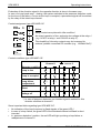
1
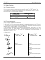
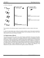
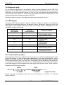
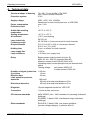
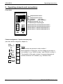
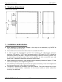
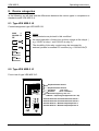
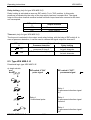
Operating instructions
Traffic detector
VEK M2E-2
FEIG ELECTRONIC GmbH Lange Straße 4 35781 Weilburg/Lahn
VEK M2E-2
© Copyright 1998 by
Operating instructions
FEIG ELECTRONIC GmbH
Lange Straße 4
D - 35781 Weilburg
The indications made in these operating instructions may be altered without previous notice.
With the edition of these instructions, all previous editions become void.
Composition of the information given in this manual has been done to the best of our
knowledge. FEIG ELECTRONIC does not guarantee the correctness of the details given in
these instructions and may not be held liable for damages ensuing from incorrect installation.
Since, despite all our efforts, errors may not be completely avoided, we are always grateful
for your useful tips.
The installation instructions given in this manual are based on advantageous boundary
conditions. FEIG ELECTRONIC does not give any guarantee promise for perfect function of
the appliance in a cross surrounding.
Copy or reproduction of these instructions, even if only partial, as well as translation into
other languages is forbidden unless a written consent has been granted by FEIG
ELECTRONIC. This also applies to the complete or partial storage of these operating
instructions on modern input- and output media for further processing in data processing
systems.
Please read the operating- and safety instructions thoroughly before putting the
appliance into operation !
Issue: 02.03.06 as
Bes-m2e_UK.doc
2
03/06
FEIG ELECTRONIC GmbH
Operating instructions
VEK M2E-2
Contents
1. General............................................................................................................... 4
2. Adjustment possibilities ...................................................................................... 5
2.1. Sensitivity.............................................................................................. 5
2.2. Frequency ............................................................................................. 5
2.3. Holding time .......................................................................................... 5
2.4. Output function...................................................................................... 6
2.4.1. Presence detection.................................................................. 6
2.4.2. Directional detection ................................................................ 6
2.5. Readjustment (Reset) ........................................................................... 8
3. Outputs and LED-display.................................................................................... 9
3.1. Working principle of the relays .............................................................. 9
3.2. Contact conditions of the relays ............................................................ 9
3.3. Loop failure ........................................................................................... 9
3.4. Diagnostic plug ..................................................................................... 10
3.5. LED-display........................................................................................... 10
3.6. Output of loop frequency....................................................................... 10
4. Technical data .................................................................................................... 11
5. Operating elements and connections ................................................................. 12
6. Housing dimensions ........................................................................................... 13
7. Installation and initiation ..................................................................................... 13
8. Device categories ............................................................................................... 14
8.1. Type VEK M2E-2 -B.............................................................................. 14
8.2. Type VEK M2E-2 -D ............................................................................. 14
8.3. Type VEK M2E-2 -E.............................................................................. 15
9. Safety instructions .............................................................................................. 17
FEIG ELECTRONIC GmbH
03/06
3
VEK M2E-2
Operating instructions
1. General
The induction loop detector is a system used for inductive vehicle detection.
Range of application:
• Barrier controls
• Door- and gate controls
• Parking- and traffic engineering
Characteristic features:
• evaluation of two loops
• galvanic separation of loop and detector electronics
• automatic system adjustment directly after switch-on
• continuous rebalancing of frequency drifts in order to avoid environmental influences
• suitable for individual job control
• no influence on loop 1 and loop 2 through multiplexing
• sensitivity adjustment independent of loop inductivity
• occupied-signal emitted by LED-display
• potential-free relay contacts as outputs
• Relay triggering may be converted from static current- to operating current principle by
switch operation.
• loop breach- or loop closing message via LED-signal
• indication of occurred and eliminated loop failures
• indication of base frequency by flash signals of the green LED
• diagnosis by external diagnostic device
• 11-pole circular connector
Possibilities of adjustment:
• two frequency levels to be used by both channels
• four sensitivity levels per channel
• Holding time: 5 minutes or infinite for both channels
• presence- or directional detection
• permanent- or pulse signal for relay channel 2
• permanent direction signal or pulse direction signal l
Structural shape:
• Housing 76x38x71mm (HxWxL) with 11-pole circular connector, RAL 5005
• 2 boards, 72x65mm each
For planning and installation of induction loops, please refer to our manual „vehicle detection
with the induction loop detector“.
4
03/06
FEIG ELECTRONIC GmbH
Operating instructions
VEK M2E-2
2. Adjustment possibilities
2.1. Sensitivity
By adjusting the sensitivity for each channel, we determine, which change of inductivity a
vehicle has to cause in order to set the detector’s output.
Sensitivity adjustment is done separately for each channel in 4 levels and according to the
dual system, with 2 DIP-switches. Adjustment for channel 1 is done with DIP-switches 1and2
and for channel 2 with DIP-switches 3 and 4.
Channel 1
DIP-switch 1
Sensitivity level
2
Channel 2
DIP-switch 3
4
1 low
(0,64% ∆f/f)
OFF OFF
OFF OFF
2
(0,16% ∆f/f)
ON
ON
3
(0,04% ∆f/f)
OFF ON
OFF ON
4 high
(0,01% ∆f/f)
ON
ON
OFF
ON
OFF
ON
2.2. Frequency
The detector’s working frequency may be selected in two common levels, to be used for both
channels. The admissible frequency range is 30kHz to 130kHz. The frequency depends on
the loop geometry, number of turns, loop supply line and the chosen switch position.
One common frequency may be adjusted for both channels with DIP-switch 5.
DIP-switch
5
ON
OFF
Frequency level
High
Low
2.3. Holding time
The common holding time for both channels may be adjusted with DIP-switch 6.
DIP-switch position
6
OFF
ON
Holding time
5 minutes
Infinite
After the holding time has expired, the "loop free" signal is indicated and the loops will be
automatically readjusted. The holding time of a detector channel starts with the assignment
of the respective loop.
FEIG ELECTRONIC GmbH
03/06
5
VEK M2E-2
Operating instructions
2.4. Output function
2.4.1. Presence detection
For the presence detection mode, you have to put DIP-switch 7 in "OFF" position. The
output signal for the relay at channel 2 is selected with the help of DIP-switch 8, while a
permanent signal is emitted at relay 1 for channel 1.
Output signal
channel 2 / relay 2
Permanent signal
Pulse when vehicle leaves
loop 2
DIP-switch position
8
OFF
ON
2.4.2. Directional detection
(not for all types; see 8. Device categories)
If DIP-switch 7 is "ON", two directional logics will be supported in dependence on DIP-switch
8. The directional pulse is mainly used in counting devices, whereas the permanent direction
signal is used for requests in gate- and barrier control units.
In the following, we will explain the function of the directional logic, taking loops 1 and 2 with
direction of motion 1Æ2 as an example. The direction signal is emitted by the relay of the
loop that the vehicle crosses first. This means that the signal will be indicated by relay 1 if
the direction of motion is 1Æ2 .
a) Single vehicle
1
2
DIP-switch 8 "ON"
pulse signal
DIP-switch 8 "OFF"
permanent signal
Relay 1
Æ directional pulse
Relay 1
Æ permanent direction signal
'on'
Ð
1
2
Ð
1
2
Ð
1
Relay 1
Æ permanent direction signal
'remains'
2
Ð
1
6
Relay 1
Æ permanent direction signal
'off'
2
03/06
FEIG ELECTRONIC GmbH
Operating instructions
VEK M2E-2
b) Queue traffic
1
2
DIP-switch 8 "ON"
pulse signal
DIP-switch 8 "OFF"
permanent signal
Relay 1
Æ directional pulse
Relays 1
Æ permanent direction signal
'on'
Ð
1
2
Ð
1
2
Ð
1
Relay 1
Æ permanent direction signal
'remains'
2
Ð
1
Relay 1
Æ permanent direction signal
'remains'
2
Ð
1
2
Ð
1
Relay 1
Æ permanent direction signal
'off'
Relay 1
Æ directional pulse
2
Ð
1
Relay 1
Æ permanent direction signal
'remains'
2
Ð
1
Relay 1
Æ permanent direction signal
'off'
2
FEIG ELECTRONIC GmbH
Relay 1
Æ permanent direction signal
'on'
03/06
7
VEK M2E-2
Operating instructions
c) Vehicle rolling back
1
2
DIP-switch 8 "ON"
pulse signal
DIP-switch 8 "OFF"
permanent signal
Relay 1
Æ directional pulse
Relay 1
Æ permanent direction signal
'on'
Ð
1
2
Ð
1
2
Ð
1
2
Ð
1
Relay 1
Æ permanent direction signal
'off'
2
Relay 2
Æ directional pulse
indicates vehicle is rolling back
The evaluation of the direction signal in opposite direction of motion is done in the same
way.
In case of a loop breach resp. closing, the system switches over to the presence detection
mode for the time of the failure. A permanent signal is now emitted by the relay of the intact
loop channel as soon as the loop is occupied.
2.5. Readjustment (Reset)
The detector automatically carries out a loop frequency adjustment as soon as the power
supply is switched on. In case of a short-term voltage loss <0,3s, no readjustment will be
carried out; conditions remain stored. A readjustment may be triggered manually by pressing
the reset key. If the loop frequency is stable, the adjustment time is approx. 1s. If the loop is
occupied during this adjustment phase, the adjustment time will be extended accordingly. In
case that the loop is permanently occupied during the adjustment process, the detector will
be readjusted as soon as the vehicle has left the loop. Due to this, the following vehicles will
again be detected. Longer adjustment times hint to an unstable loop frequency. The
loop/detector system has to be checked with regard to possible interferences.
8
03/06
FEIG ELECTRONIC GmbH
Operating instructions
VEK M2E-2
3. Outputs and LED-display
3.1. Working principle of the relays
The detector has a potential-free relay contact at each output. The static current- or
operating current principle may be selected for each channel with the help of a slide switch.
Switch
Position
right
Static current principle
(Relay coil falls off during signal output)
left
Operating current principle
(Relay coil attracts during signal output)
1
2
1
2
Working principle
3.2. Contact conditions of the relays
(For device categories, please refer to chapter 8)
The following chart illustrates the relay’s condition depending on the selected relay working
principle and the detector condition.
Detector condition
Loop is free
Loop is occupied
Loop failure
Reset
Voltage off
3.3. Loop failure
In case of a loop failure, the relay of the disturbed channel changes into the „loop is
occupied“ condition. The green LED goes out. The red LED lights up.
After the fault has been eliminated, the detector channel keeps on working independently.
The green LED pulsates now, in order to hint to the fault which has occurred and already
been eliminated. This fault indicator is restored by pressing the reset key.
FEIG ELECTRONIC GmbH
03/06
9
VEK M2E-2
Operating instructions
3.4. Diagnostic plug
For an optimum adjustment of the detector, please connect diagnostic device VEK FG2.
Diagnostic device VEK FG2 indicates all relevant data for initiation and service. It provides
information on the loop/detector system, so that we may then optimise the adjustments as
well as localise the cause for malfunctions. For further information, please refer to the
operating instructions of diagnostic device VEK FG2.
Warning: please only plug in the diagnostic cable when the detector is idle !
3.5. LED-display
The green LED indicates that the detector channel is ready for operation and sends out
important hints regarding initiation of the detector (failure, adjustment, frequency output) via
flash signals. The red LED indicates activation of the relay output in dependence on the
availability condition of the loop.
Green LED
Loop control
Off
Red LED
Loop condition
off
Flashes
flashes after adjustment
On
off
off
On
on
Off
Pulsates
on
off
Pulsates
on
Detector condition
Reset or
Lack of supply voltage
Adjustment
Loop frequency output
Detector ready,
loop free
Detector ready,
loop occupied
Loop failure
Loop free,
after temporary failure
Loop occupied,
after temporary failure
3.6. Loop frequency output
After the detector has been readjusted, the loop frequency is indicated by flash signals of the
green LED. Approx. 1s after the successful readjustment, the output starts with the 10kHzposition of the frequency value. The green LED of the detector channel will flash 1 time per
10kHz loop frequency. After a 1s break, the 1kHz-position will be indicated in the same way.
In case that the units digit has the valency '0', 10 flash signals will be emitted. The duration
of the flash signals of the 1kHz-position is a little shorter than the one of the 10kHz- position.
Example of a 57kHz loop frequency:
Zehner
Einer
1s
5x 10kHz
7x 1kHz
entspricht: 57kHz
If both channels are adjusted at the same time, the frequency of channel 1 is indicated
before channel 2.
10
03/06
FEIG ELECTRONIC GmbH
Operating instructions
VEK M2E-2
4. Technical data
Structural shape of housing
Protective system
Supply voltage
Power consumption
Protection class
76 x 38 x 71 mm (HxBxL), Ral 5005
with 11-pole circular connector
IP 40
230V +10%/-15%, 50/60Hz
transformer is short circuit-proof acc. to VDE 0551
max. 3 VA
II
Admissible working
temperature
Storing temperature
Air moisture
-20 °C to +70 °C
Loop inductivity
Frequency range
Responsiveness
Holding time
20-700 µH
30-130 kHz in 2 common levels for both channels
0,01 % to 0,65 % (∆f/f) in 4 levels per channel
0,02 % to 1,3 % (∆L/L)
5 min. or infinite, for both channels
Loop supply line
Loop resistance
< 250 m
< 20 Ohm (incl. supply line)
-40 °C to +70 °C
< 95 % non-thawing
Break-contact (make-contact for type -E)
250V AC, 4A, 1000 VA (resistive load AC)
Minimum contact load 0,25mW/10mV/1mA
Operating-/static current principle may be selected with
switch
Testing voltage
coil-contact 4000V AC
Contact-contact 1000V AC
Duration of signal, pulse time > 200 ms
80 ms
Cycle time
160 ms
Reaction time
Limit speed for presence
100 km/h
detection
90 km/h at a loop head distance of 2m
45 km/h at a loop head distance of 1m
Directional detection
Relay
Diagnosis
10-pole diagnostic socket for 'VEK FG2'
Connection
11-pole circular connector
CE-relevant standards
prEN 50082-2, Nov. 1994 resistance to jamming (Industrial
buildings)
EN 50081-1, March 1993 interference output (domestic
buildings)
Other standards
EN 61010-1, March 1994 low tension guideline
(excess-voltage category II, pollution level 2)
FEIG ELECTRONIC GmbH
03/06
11
VEK M2E-2
Operating instructions
5. Operating elements and connections
Front view:
VEK M2E
1
2
3
4
5
6
7
8
1
Empfindlichkeit Kanal 1
2
F
H 5min.
Empfindlichkeit Kanal 2
Frequenz
low / high
Haltezeit
5min / unendlich
Richtungslogik aus / ein
Dauersignal / Impulssignal
Service
1
Schleifenzustand / Schleifenkontrolle Kanal 1
2
Schleifenzustand / Schleifenkontrolle Kanal 2
1
Schalter Arbeits- / Ruhestromprinzip Kanal 1
Schalter Arbeits- / Ruhestromprinzip Kanal 2
2
Reset
Contact assignment 11-pole connector plug:
(see also: device categories, chapter 8)
230V
L
50-60Hz N
PE
12
1
2
9
2
3
4
1
5
6
1
7
8
2
10
11
Notice:
Relay contacts are pictured in idle condition !
Mixed operation of extra-low- and low voltage at the relays is
not admitted ! ( e.g. 24VDC at relay 1 and 230VAC at relay 2 ).
The durability of the relay contacts is increased by external,
parallel connected RC modules (e.g. 100Ohm/10nF)!
03/06
FEIG ELECTRONIC GmbH
Operating instructions
VEK M2E-2
6. Housing dimensions
Dimensioned drawing:
7. Installation and initiation
•
•
•
•
•
•
Mixed operation of extra-low/low voltage at the relays is not admitted (e.g. 24VDC at
relay 1 and 230V AC at relay 2) !
The isolation of the connection cables has to be suitable for 230V !
In order to set the loop/detector system into operation, the adjustments ‚presence
detection‘ (DIP-switch 7 ‚OFF‘) and ‚permanent signal‘ (DIP-switch 8 ‚OFF‘) should be
selected at detector VEK M2E. The perfect functioning of detector and relay outputs may
be checked by seizing the loops. After having passed the test successfully, you may
switch over to directional detection resp. pulse signal output.
When selecting the frequency level, please keep a frequency distance of approx. 15 kHz
to the loop frequency of a neighbouring detector.
The sensitivity level should only be chosen as high as necessary. It has to be adjusted to
the loop geometry and to the object to be detected.
The device is intended for installation in a switch cabinet. The switch cabinet has to have
a continuous base isolation. Installation of this device outside a switch cabinet-like
housing is not admitted.
FEIG ELECTRONIC GmbH
03/06
13
VEK M2E-2
Operating instructions
8. Device categories
In the following, we will deal with the differences between the various types in comparison to
standard model VEK M2E-2-A.
8.1. Type VEK M2E-2 -B
Contact assignment type VEK M2E-2-B:
230V
L
50-60Hz N
PE
1
2
9
Notice:
Relay contacts are pictured in idle condition !
1
3
4
No mixed operation of extra-low- and low voltage at the relays! (
e.g. 24VDC at relay 1 and 230VAC at relay 2 ).
2
5
6
The durability of the relay contacts may be increased by
external, parallel connected RC modules (e.g. 100Ohm/10nF)!
2
7
8
1
10
11
8.2. Type VEK M2E-2 -D
Front view of type VEK M2E-2-D:
VEK M2E
1
2
3
4
5
6
7
8
1
Empfindlichkeit Kanal 1
2
F
H 5min.
Empfindlichkeit Kanal 2
Frequenz
low / high
Haltezeit
5min / unendlich
Relaisverriegelung aus / ein
Dauer- / Impulssignal (Sperrzeit 10s / 5s)
Service
1
2
1
Schleifenzustand / Schleifenkontrolle Kanal 1
2
Schleifenzustand / Schleifenkontrolle Kanal 2
Schalter Arbeits- / Ruhestromprinzip Kanal 1
Schalter Arbeits- / Ruhestromprinzip Kanal 2
Reset
14
03/06
FEIG ELECTRONIC GmbH
Operating instructions
VEK M2E-2
Relay locking: (only for type VEK M2E-2-D)
Relay locking is activated as soon as DIP-switch 7 is in "ON" position. In this mode,
presence is indicated by the relay of the loop which has been occupied first. The signal
output of the other channel remains locked until both loops have been crossed or the timeout has expired.
DIP-switch
7
OFF
ON
Output function
Presence detection
Relay locking
Time-out: (only for type VEK M2E-2-D)
The time-out is selected in the output mode relay locking, with the help of DIP-switch 8. In
case of presence detection, it can be used to choose the signal output for channel 2.
DIP-switch
8
Output function
Presence detection
Relay locking
Permanent signal during
Time-out 10s
presence on loop 2
for both channels
Pulse when leaving loop 2
Time-out 5s
for both channels
OFF
ON
8.3. Type VEK M2E-2 -E
Directional logic type VEK M2E-2-E:
a) single vehicle
1
2
DIP-switch 8 "ON"
pulse signal
DIP-switch 8 "OFF"
permanent signal
Ð
1
2
Ð
1
Relay 1
Æ permanent direction signal
'on'
2
Ð
1
2
Relay 1
Æ directional pulse
Relay 1
Æ permanent direction signal
'remains'
Ð
1
Relay 1
Æ permanent direction signal
'off'
2
FEIG ELECTRONIC GmbH
03/06
15
VEK M2E-2
Operating instructions
Evaluation of the direction signal in the opposite direction is done in the same way.
In case of a loop break resp. –closing, the system switches to the presence detection mode
for the time of the failure. A soon as the loop is occupied, a permanent signal will be emitted
by the relay of the intact loop channel.
Contact assignment type VEK M2E-2-E:
230V
50-60Hz
L
N
1
2
1
3
4
2
5
6
2
9
7
8
1
10
11
Notice:
Relay contacts are pictured in idle condition !
No mixed operation of low- and extra-low voltage at the relays !
( e.g. 24VDC at relay 1 and 230VAC at relay 2 ).
The durability of the relay contacts may be increased by
external, parallel connected RC-modules (e.g.. 100Ohm/10nF)!
Contact conditions type VEK M2E-2-E:
Channel 1
Channel 2
Detector condition
9
7
9
7
Loop is free
8
9
8
7
9
7
Loop is occupied
8
Loop failure,
readjustment
9
*)
8
7
9
7
*)
8
9
8
7
9
7
Reset
8
9
8
7
9
7
Voltage off
8
8
*) In case of presence detection, an inverted signal is emitted for this
detector condition at channel 1!
Some important hints regarding type VEK M2E-2-E:
•
•
•
16
No indication of the loop frequency by flash signals of the green LED !
In case of a loop failure, the green LED of the disturbed channel will flash in short
intervals !
In „presence detection“ position, the red LED will light up during a loop failure or
readjustment of channel 1!
03/06
FEIG ELECTRONIC GmbH
Operating instructions
VEK M2E-2
9. Safety instructions
•
•
•
•
•
•
•
•
•
•
•
•
•
•
The device may only be used for the purpose intended by the manufacturer.
The operating instructions have to be handed out to every user and kept in an easily
accessible place.
Unacceptable changes as well as the use of spare parts and special features which are
not sold or recommended by the manufacturer, may cause fire, electric shocks and
injuries. Therefore, such measures lead to nonliability of the manufacturer and a lapse of
all warranty claims.
The appliance is subject to the manufacturer’s guarantee regulations in the version valid
at the time of purchase. We cannot be held liable for improper or faulty manual or
automatic adjustment of parameters resp. improper use of the appliance.
Repair work may only be carried out by the manufacturer.
Installation, initiation, maintenance, measuring and adjustment of the traffic detector
should only be carried out by electricians with a good knowledge of the rules for
prevention of accidents.
When handling appliances that get in contact with electricity, the valid VDE-regulations
have to be observed. In particular, these are: VDE 0100, VDE 0550/0551, VDE 0700,
VDE 0711, VDE 0860, VDE 0105 as well as the rules for the prevention of accidents and
fire, VBG4.
If an operation display goes out, this is not a proof that the appliance is disconnected
from the mains and idle.
All labour that is carried out on the appliance as well as its initiation, has to conform to the
national as well as the local electric regulations.
The user has to make sure that the appliance is installed and operated according to the
technical rules of the country of installation as well as other regional regulations. Cable
dimensions, protection, grounding, disconnection, insulation control and excess current
protection should be especially considered.
Mixed operation of low- and extra-low voltage at the two relay outputs is not admitted.
The isolation of all connecting cables to the 11-pole circular connector has to be suitable
for 230V. The circular connector conforms to the base isolation.
The diagnostic cable of the diagnostic unit VEK FG2 as well as the cover of the
diagnostic socket should only be plugged in resp. removed if the traffic detector is idle. As
soon as the diagnostic procedure is terminated, the cover has to be put back into place.
According to machine directive 89/392/EWG, appendix IV, the appliance must not be
used as a safety component. Systems with a high danger potential need additional safety
contrivances !
FEIG ELECTRONIC GmbH
03/06
17
VEK M2E-2
Operating instructions
Notes:
18
03/06
FEIG ELECTRONIC GmbH