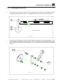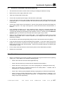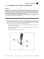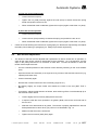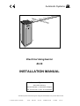
1
Automatic Systems stems atic Sy Autom 1300 IUM E - BELG WAVR TEL: 02.11 (32) 10.23. - FAX: 02.02 (32) 10.23. Electrical rising barrier BL26 INSTALLATION MANUAL Automatic Systems s.a. Head office & factory: Avenue Mercator 5, 1300 Wavre, Belgium Tel.: 32-10-23.02.11 Fax: 32-10-23.02.02 Automatic Systems reserves the right to change the characteristics of its products without notice. Automatic Systems BL26-GB YD-XX MQ-1302 30/11/95 Installation manual 1-1103GB Rev.: B Automatic Systems Table of contents 1. INTRODUCTION............................................................................................................... p. 3 2. 2.1. 2.2. 2.3. 2.4. 2.5. GENERAL......................................................................................................................... Front sectional views ...................................................................................................... Lateral sectional view ..................................................................................................... Switching off the equipment ........................................................................................... General conditions of use............................................................................................... Emergency operation ..................................................................................................... 2.5.1. Opening or closing in case of power failure .................................................... 2.5.2. In case of breakdown ...................................................................................... p. p. p. p. p. p. p. p. 4 4 6 7 7 8 8 8 INSTALLATION ................................................................................................................ Preliminary work on site ................................................................................................. Handling and installing the unit....................................................................................... Installing the barrier arm................................................................................................. General dimensions and characteristics ........................................................................ Levelling the barrier arm................................................................................................. Installing the arm tip support (option) ............................................................................. Electrical connections and initial power-up .................................................................... Check-list ........................................................................................................................ Temporary dismantling ................................................................................................... 3.9.1. Disconnecting the equipment.......................................................................... 3.9.2. Dismantling the barrier arm............................................................................. 3.9.3. Removing the unit ........................................................................................... 3.10. Scrapping the equipment................................................................................................ p. p. p. p. p. p. p. p. p. p. p. p. p. p. 9 9 9 10 11 12 13 14 14 15 15 15 16 16 4. 4.1. 4.2. 4.3. 4.4. 4.5. ADJUSTMENTS AND TECHNICAL INTERVENTIONS .................................................. Arm balance adjustment................................................................................................. Belt tension adjustment .................................................................................................. Safety torque limiter adjustment ..................................................................................... Limit switch adjustment .................................................................................................. 4.4.1. Electrical closing test....................................................................................... 4.4.2. Electrical opening test ..................................................................................... Replacing the balance spring ......................................................................................... p. p. p. p. p. p. p. p. 17 17 18 20 21 22 22 24 5. MAINTENANCE................................................................................................................ p. 27 6. ANNEX 1: TECHNICAL SHEET 7. ANNEX 2: ELECTRICAL DIAGRAMS 8. ANNEX 3: INSTALLATION PLAN 9. ANNEX 4: SPARE PARTS 10. ANNEX 5: RECOMMENDED SPARE PARTS 3. 3.1. 3.2. 3.3. 3.4. 3.5. 3.6. 3.7. 3.8. 3.9. Automatic Systems BL26-GB YD-XX MQ-1302 30/11/95 Installation manual 1-1103GB Rev.: B p. 2/27 Automatic Systems 1. INTRODUCTION We thank you for having chosen the electrical rising barrier type BL26 designed and manufactured by Automatic Systems. We are confident that your purchase will fully meet your requirements. However, in order to obtain maximum satisfaction from this equipment for a maximum period of time, we strongly advise you to read this manual carefully before installing the equipment. Although this manual has been prepared with great care, some information may seem erroneous or unclear to you. In this case, please do not hesitate to contact us with your remarks or questions. WARNING: YOUR RISING BARRIER TYPE BL26 COMPRISES A MECHANISM AND VARIOUS ELECTRICAL COMPONENTS. ANY NEGLIGENCE DURING AN INTERVENTION IN THE MACHINE MAY SERIOUSLY ENDANGER YOUR SAFETY. AS SOON AS YOU OPEN THE HOUSING, SWITCH OFF THE MAGNETO-THERMAL CIRCUIT BREAKER OF THE ELECTRICAL CONTROL BOARD LOCATED BEHIND THE SIDE DOOR. BE CAREFUL IN HANDLING ANY INTERNAL ELEMENT WHICH MIGHT BE UNDER POWER OR COULD BE SET IN MOTION. THE HOOD SHOULD BE REMOVED ONLY IF YOU NEED TO REPLACE THE DRIVING SHAFT OR THE BALANCE SPRING, ADJUST THE BELT OR PROCEED WITH THE MAINTENANCE. IMPORTANT INFORMATION CONCERNING HEALTH & SAFETY PROCEDURES The introduction of a pedestrian or vehicle barrier product as manufactured by Automatic Systems places a duty of responsibility for the safety and well-being of any user(s) or person(s) in close proximity to such equipment. You are required therefore to observe and put in place appropriate safety measures, as deemed necessary. ♦ Pedestrian flow must be prohibited anywhere within a vehicle barrier passage-way, unless the movement of the barrier system is clearly indicated, e.g. audible and/or visual signals, floor marking, notices, etc. ♦ Access keys to any of the internal mechanisms can only be issued to authorised and qualified personnel, aware of the relevant electrical and mechanical safety codes and regulations in force. All equipment housing must be kept locked. You have a legal obligation and responsibility to enforce good safety practices at all times. See also note below. Note: In the countries of the European Union, the requirement 1.3.7.2 of the EC Machines Directive prescribes that the pictogram for "Dangerous area* -- no entry for pedestrians" be affixed on both sides of the equipment (* within 1 meter of the barrier arm in its closed position). black white red Automatic Systems BL26-GB YD-XX MQ-1302 30/11/95 Installation manual 1-1103GB Rev.: B p. 3/27 Automatic Systems 2. 2.1. GENERAL Front sectional views 1:7 1:8 1:2 1:3 1:4 1:5 1:6 1:1 1:9 1:10 1:11 Solution 1 & 2 Legend: 1:1 Motor 1:2 Gearbox 1:3 Safety torque limiter 1:4 Limit switches 1:5 Balance spring (arm length over 2.90 metres) 1:6 Driving belt 1:7 Hood 1:8 Driving shaft 1:9 Motor control board (or "logic") 1:10 Earth bolts 1:11 Housing Fig. 1 Automatic Systems BL26-GB YD-XX MQ-1302 30/11/95 Installation manual 1-1103GB Rev.: B p. 4/27 Automatic Systems 2:7 2:8 2:2 2:3 2:4 2:5 2:6 2:1 2:9 2:10 2:11 Solution 3 & 4 Legend: 2:1 Motor 2:2 Gearbox 2:3 Safety torque limiter 2:4 Limit switches 2:5 Balance spring (arm length over 2.90 metres) 2:6 Driving belt 2:7 Hood 2:8 Driving shaft 2:9 Motor control board (or "logic") 2:10 Earth bolts 2:11 Housing Fig. 2 Automatic Systems BL26-GB YD-XX MQ-1302 30/11/95 Installation manual 1-1103GB Rev.: B p. 5/27 Automatic Systems 2.2. Lateral sectional view 3:7 3:8 3:4 3:2 3:12 3:3 3:5 3:6 3:1 3:9 3:10 3:11 Legend: 3:1 Motor 3:2 Gearbox 3:3 Safety torque limiter 3:4 Arm-fixing jaw 3:5 Balance spring (arm length over 2.90 metres) 3:6 Driving belt 3:7 Hood 3:8 Driving shaft 3:9 Motor control board (or "logic") 3:10 Earth bolts 3:11 Housing 3:12 Abutment Fig. 3 Automatic Systems BL26-GB YD-XX MQ-1302 30/11/95 Installation manual 1-1103GB Rev.: B p. 6/27 Automatic Systems 2.3. Switching off the equipment 4:7 4:6 4:5 4:4 4:3 4:1 Logic control type B4 4:2 Legend: 4:1 Magneto-thermal circuit breaker 4:2 Terminals L and N 4:3 Earth point 4:4 General connection block 4:5 Presence detector connector 4:6 Motor terminal block 4:7 Fuse supports Fig. 4 • As soon as you open the housing, switch off the magneto-thermal circuit breaker (4:1) of the motor control board, located behind the side door. 2.4. • General conditions of use Your electrical rising barrier type BL26 has been designed to operate in any kind of climatic environment, from -15°C (*) to +70°C, with up to 95% of relative humidity. (*) Without optional heater. Automatic Systems BL26-GB YD-XX MQ-1302 30/11/95 Installation manual 1-1103GB Rev.: B p. 7/27 Automatic Systems 2.5. • Emergency operation The following instructions are to be given to the installation supervisor. 2.5.1. Opening or closing in case of power failure -- Open the side door. -- Switch off the magneto-thermal circuit breaker (4:1) of the motor control board. -- Grasp the driving belt (1:6) and act on it in either direction to unlock the barrier arm mechanically from its closed or open position, then raise or lower the arm by hand until the desired position is reached. 2.5.2. In case of breakdown -- Check the general power supply. -- Open the side door. -- Check the state of the two fuses on the electrical control board. -- Check the tension of the power supply to the magneto-thermal overload protection of the electrical control board, and check if the protection is properly engaged (circuit breaker ON). -- Check all wire connections. Some connections may need to be tightened. -- Check the connection of the control wires referring to the electrical diagram inside the housing. -- Proceed with an electrical opening/closing test by means of the external control tool (e.g. optional push button box). -- Put the side door in place again and lock it. Note: If the trouble persists after you carry out the checks above, call your local Automatic Systems agent. Automatic Systems BL26-GB YD-XX MQ-1302 30/11/95 Installation manual 1-1103GB Rev.: B p. 8/27 Automatic Systems 3. INSTALLATION 3.1. • Preliminary work on site This is basically the following: -- PVC tube (minimum diameter 60mm) to be provided to allow the power supply and remote control wires to exit from within the concrete base. -- Construction of a concrete base according to the instructions of plan Nr CH2790. A barrier installation basement kit is available as an optional accessory. -- Wiring (to be provided by the customer, according to the legal prescriptions in use in the country of installation): # # 3.2. Power supply (from the general power supply box to the concrete base) Control wiring (from the place where the control tool will be installed to the concrete base). Ensure that the cables have a minimum of 1 metre out of the concrete base. Handling and installing the unit • The barrier has been packaged suitable for transport. Carry the material to the installation site, place the unit upright and dismantle the conditioning materials. • Unlock and remove the side door. Keys are attached on the arm-fixing jaw (3:4) by means of adhesive tape. • Unlock and remove the hood. • Check the state of the equipment. Though it has been carefully packed, damage may have occurred during transport: in this case, do not forget to advise your local Automatic Systems agent or your insurance company. If need be, proceed with the necessary repairs. • Strip the insulation of the cables along approx. 50cm. • Place the barrier on its concrete base respecting the orientation desired with regard to the roadway. • Draw a mark in each of the four oblong holes at the bottom of the housing inside the unit, then remove the barrier. • Drill four holes on the marks you have just drawn on the concrete base, and fix expansible bolts (e.g. "Rawlbolt" type) in these. • Position the barrier again and secure it to the concrete base. • If required, add shims between the sealing frame and the housing in order to ensure the barrier is perfectly level. Note: Since final adjustment of the alignment with the roadway may be necessary after the arm is installed, do not block the barrier onto the concrete base firmly now. Automatic Systems BL26-GB YD-XX MQ-1302 30/11/95 Installation manual 1-1103GB Rev.: B p. 9/27 Automatic Systems 3.3. Installing the barrier arm 5:4 5:2 5:1 5:3 Fig. 5 • Remove the three screws (5:1) and the flat washers (5:2) from the arm-fixing jaw (5:3). • Position the arm boom (5:4) onto the arm-fixing jaw, and fix the flat washers (5:2) and the screws (5:1) again as illustrated above. • Check the alignment of the arm boom with the arm-fixing jaw, and tighten the screws (5:1) firmly. • Grasp the driving belt (1:6) and act on it to unlock the mechanism, then lower the arm by hand to the horizontal position. • Check the alignment of the complete barrier with the roadway and adjust if necessary. • If no arm tip support is to be installed, block the barrier onto the concrete base. Automatic Systems BL26-GB YD-XX MQ-1302 30/11/95 Installation manual 1-1103GB Rev.: B p. 10/27 Automatic Systems 3.4. General dimensions and characteristics MAX.: 5000mm 475 380 95 870 1050 380 360 Fig. Solution 1 (standard) Solution 2 Solution 4 Solution 3 Fig. 7 Note: For more information on the logic control, the exact model of barrier to install or the correct choice of loops to use (depending on the site configuration, etc.), please refer to the corresponding data sheets or contact your local Automatic Systems agent. Automatic Systems BL26-GB YD-XX MQ-1302 30/11/95 Installation manual 1-1103GB Rev.: B p. 11/27 Automatic Systems 3.5. • Levelling the barrier arm The barrier is closed in the "0 position" if the points (x), (y) and (z) of the crankshaft-rod device are perfectly aligned as shown below. If the alignment is correct, the arm must be horizontal. x y z (Arm horizontal) Fig. 8 • Check if the arm is perfectly vertical in its open position, then lower it to the closed position. If the arm is horizontal, go directly to paragraph 3.6. If this is not the case while the points (x), (y) and (z) are aligned, adjust the arm level as follows, e.g. if the barrier is not precisely level with the ground: 9:2 9:1 Fig. 9 Automatic Systems BL26-GB YD-XX MQ-1302 30/11/95 Installation manual 1-1103GB Rev.: B p. 12/27 Automatic Systems -- Loosen the lock nut (9:1). -- Loosen the eccentric screw (9:2) very slightly to adjust the arm level. -- When the desired arm level is reached, tighten the lock nut (9:1) firmly again. -- So, the "0 position" implies: 3.6. Arm horizontal. Points (x), (y) and (z) aligned. Motor stopped. Limit switch (15:1) engaged. Installing the arm tip support (option) • The arm tip support is supplied as an option. • The tip support must be fixed onto a flat and level concrete base by means of four rawlbolts following the instructions of plan Nr CH2656. Its role is to assure the rigidity of the arm and maintain its tip when in the closed position. • If required, adjust the height of the tip support as follows: 10:1 10:2 Fig. 10 -- Remove the screw (10:1). -- Rotate the fork (10:2) of the tip support in either direction so that the arm tip just rests on it when the arm is locked in the closed position. -- Fix the screw (10:1) again. -- Align the arm in the tip support, if necessary by rotating the barrier on its concrete base. -- Block the barrier onto the concrete base. Automatic Systems BL26-GB YD-XX MQ-1302 30/11/95 Installation manual 1-1103GB Rev.: B p. 13/27 Automatic Systems 3.7. Electrical connections and initial power-up • The electrical connections must be made according to the diagram inside the housing. • Make sure the power supply cables are not live. • Take down the electrical control board. • Connect the one-phase power supply to the terminals L and N (4:2). • Connect the earth wire to the bolt (1:10) located at the bottom of the housing inside the unit, and make sure there is a connection between this bolt and the earth point (4:3) of the electrical control board. • Connect the control wires to the terminals 2, 5 and 6 of the general connection block (4:4) for a logic control type B4. For a logic control type C4, connect the control wires to the terminals 2, 5, 6 and 8. • If the installation includes one (or more) detection loop(s), check the connection between the detector(s) and the control board. Connect the wires of the closing loop to the terminals 9 and 10, and of the opening loop (if existing) to the terminals 11 and 12. Contact your local Automatic Systems agent if you wish to know more about the various types of logic control. • Switch on the magneto-thermal circuit breaker (4:1). If the installation includes one (or more) detection loop(s), make sure no vehicle is present on the loop(s) since this might distort the detector(s)' sensitivity. • Proceed with an electrical opening/closing test by means of the external control tool (option). • It may be that the motor runs without activating the mechanism. In this case, switch off the circuit breaker and reverse the connection of the motor terminals J2.2 and J2.4 on the terminal block (4:6) at the rear side of the electrical board. Re-arm the overload protection by switching the circuit breaker on again. • Fix the cables under the electrical control board by means of the cable binders provided. • Replace the control board. 3.8. • Check-list Before commissioning your barrier type BL26, proceed with the general electrical tests (opening, closing, etc.). Then make sure to review the following points: -- Check if all screws and nuts have been tightened firmly. -- Check if all wires are firmly connected to their respective terminal blocks. -- Check if the arm is correctly fixed. If not, refer to paragraph [3.3. Installing the barrier arm]. -- Check if the barrier arm is perfectly horizontal in the closed position. If needed, refer to paragraph [3.5. Levelling the barrier arm]. -- Check if the V-belt is properly adjusted referring to paragraph [4.2. Belt tension adjustment]. -- Check if the arm reopens with difficulty in case a closing movement is reversed, or if it cannot be stopped by hand during a manoeuvre. If necessary, refer to paragraph [4.3. Safety torque limiter adjustment]. Automatic Systems BL26-GB YD-XX MQ-1302 30/11/95 Installation manual 1-1103GB Rev.: B p. 14/27 Automatic Systems -- Open and close the barrier electrically: check if the arm stops in the vertical position, with motor stopped, and if the three points (x), (y) and (z) of the crankshaft-rod device are perfectly aligned in the closed position, also with motor stopped. If not, refer to paragraph [4.4. Limit switch adjustment]. -- Check if you did not forget any tool inside the barrier. -- Remove any foreign body from the inside of the barrier (scraps, etc.) and clean. -- Replace and lock the hood. -- Replace and lock the side door. -The barrier is now operational. Although all adjustments have been carried out in factory, a final regulation may be required after the transport or mounting procedure. In this case, see chapter [4. Adjustments and technical interventions]. 3.9. • Temporary dismantling If the equipment has to be temporarily dismantled, e.g. if you need to change its place, proceed in the following order. 3.9.1. Disconnecting the equipment -- Unlock and remove the side door. -- Make sure the power supply cables are not live. -- Switch off the circuit breaker (4:1) on the electrical control board. -- Take down the electrical control board. -- Remove the phases of the power supply from the terminals L and N (4:2). -- Disconnect the earth wire from the bolt (1:10) located at the bottom of the housing inside the unit. -- Disconnect the control wires from the general connection block (4:4). -- Disconnect any other wires (from the detection loops, etc.). -- Cut off the cable binders under the electrical control board so you can detach the cables. -- Replace the electrical control board. 3.9.2. Dismantling the barrier arm -- Grasp the driving belt (1:6) and act on it to unlock the mechanism, then raise the arm by hand up to the vertical position. -- Remove the screws (5:1) and dismount the arm. together to avoid losing any. Automatic Systems BL26-GB YD-XX MQ-1302 30/11/95 Gather all screws and flat washers Installation manual 1-1103GB Rev.: B p. 15/27 Automatic Systems 3.9.3. -- Removing the unit Remove the fixing accessories from the barrier, then remove this from the concrete base. 3.10. Scrapping the equipment • When the equipment is withdrawn from use, proceed with the dismantling procedure as described in paragraph [3.9. Temporary dismantling]. Do not fail, however, to empty the oil from the gearbox and to scrap the various elements of the machine in the appropriate way (metal parts, electronic components, etc.) in line with your country code/regulations. Automatic Systems BL26-GB YD-XX MQ-1302 30/11/95 Installation manual 1-1103GB Rev.: B p. 16/27 Automatic Systems 4. ADJUSTMENTS AND TECHNICAL INTERVENTIONS WARNING! REMINDER: YOUR RISING BARRIER TYPE BL26 COMPRISES A MECHANISM AND VARIOUS ELECTRICAL COMPONENTS. ANY NEGLIGENCE DURING AN INTERVENTION IN THE MACHINE MAY SERIOUSLY ENDANGER YOUR SAFETY. AS SOON AS YOU OPEN THE HOUSING, SWITCH OFF THE MAGNETO-THERMAL CIRCUIT BREAKER OF THE ELECTRICAL CONTROL BOARD LOCATED BEHIND THE SIDE DOOR. BE CAREFUL IN HANDLING ANY INTERNAL ELEMENT WHICH MIGHT BE UNDER POWER OR COULD BE SET IN MOTION. THE HOOD SHOULD BE REMOVED ONLY IF YOU NEED TO REPLACE THE DRIVING SHAFT OR THE BALANCE SPRING, ADJUST THE BELT OR PROCEED WITH THE MAINTENANCE. 4.1. • Arm balance adjustment In case of an arm boom length over 2.90 metres, the power needed to set the mechanism in motion is minimal due to the built-in traction spring. To operate properly, the tension of the spring must be correctly adjusted, i.e. the strength needed to activate the mechanism must be equal in either direction. If necessary, proceed with the adjustment as follows: -- Grasp the driving belt (1:6) and act on it to unlock the mechanism, then bring the arm by hand up to an angle of approx. 20°. -- Uncouple the torque limiter by loosening the four lock nuts (14:1) and the four screws (14:2) without removing them. -- Move the barrier arm manually to an angle of 45°. 11:3 11:1 11:2 Fig. 11 Automatic Systems BL26-GB YD-XX MQ-1302 30/11/95 Installation manual 1-1103GB Rev.: B p. 17/27 Automatic Systems a) If the arm moves downwards: ) Loosen the lock nut (11:1). ) Tighten the nut (11:2) smoothly against the sole (11:3) to stretch the traction spring harder and position the arm at 45°. ) When the desired result is obtained, tighten the nut (11:1) again to block the nut (11:2). b) If the arm moves upwards: • Loosen the lock nut (11:1). ) Loosen the nut (11:2) smoothly to release the spring and position the arm at 45°. ) When the desired result is obtained, tighten the nut (11:1) again to block the nut (11:2). Check the V-belt following the instructions of paragraph [4.2. Belt tension adjustment], then adjust the safety clutch referring to paragraph [4.3. Safety torque limiter adjustment]. 4.2. • ) Belt tension adjustment The tension of the belt must be adjusted after replacement or after a certain time of operation, or when all the motor power cannot be transmitted to the mechanism. As a consequence, the belt slips on the pulleys and there is a formation of black dust. Proceed as follows to check the tension and/or replace the belt. -- Arm the overload protection of the electrical control board by switching on the circuit breaker (4:1). -- Open the barrier arm electrically to an angle of 90° by means of the external control tool (e.g. optional push button box). -- Close it electrically again. -- Reverse the movement when the arm is half-way (angle of 45°). -- By slipping slightly, the torque limiter must absorb the inertia of the arm (NOT THE VBELT!). -- If necessary, adjust the belt tension as follows, after switching off the circuit breaker (4:1) on the electrical control board: ) Loosen slightly the four screws (12:1) that fix the motor. ) If required, slide the motor upwards in its guides (12:2), remove the old V-belt and fix the new one. ) Slide the motor downwards in its guides. The tension is properly adjusted if the belt can be depressed about 10mm when you push on it as illustrated in Fig. 13. ) Make sure that the motor is horizontal. ) Tighten the four screws (12:1) firmly again. Automatic Systems BL26-GB YD-XX MQ-1302 30/11/95 Installation manual 1-1103GB Rev.: B p. 18/27 Automatic Systems 12:1 12:2 12:1 Fig. 12 10mm Fig. 13 Reminder: In case a closing or opening movement is reversed, the belt must not absorb the inertia of the mechanism! Automatic Systems BL26-GB YD-XX MQ-1302 30/11/95 Installation manual 1-1103GB Rev.: B p. 19/27 Automatic Systems 4.3. • • Safety torque limiter adjustment The torque limiter is a safety device and is factory-adjusted. However, some further adjustment may be necessary when the equipment has been installed or after a certain time of operation. Proceed with the adjustment in the following cases: -- Either the barrier arm does not open easily when a closing movement is reversed. The friction clutch then slips and must be tightened. -- Or the force needed to block the arm by hand during a closing or opening movement is too strong. The friction clutch then sticks and must be loosened. -- Or after a balance adjustment with the spring (for an arm length over 2.90 metres). In either case, the state of the V-belt must first be checked according to paragraph [4.2. Belt tension adjustment]. Then proceed as follows: 14:1 14:2 Fig. 14 -- Loosen the four lock nuts (14:1). -- Tighten the four screws (14:2) to tighten the torque limiter, untighten them to loosen it. -- Arm the overload protection of the electrical control board by switching on the circuit breaker (4:1). -- Make an electrical opening/closing test by means of the external control tool (e.g. optional push button), and repeat the procedure above until the desired result is obtained. Never forget to first switch off the equipment. -- When the adjustment is completed, switch off the circuit breaker (4:1). Automatic Systems BL26-GB YD-XX MQ-1302 30/11/95 Installation manual 1-1103GB Rev.: B p. 20/27 Automatic Systems Attention: Proceed smoothly by 1/8th of a turn successively, since the adjustment is very sensitive. When the adjustment is completed, do not forget to tighten the four lock nuts (14:1) firmly again. IMPORTANT: Excessive tightening of the clutch may damage the gearbox! • 4.4. • To test the torque limiter adjustment, proceed as follows: -- Arm the overload protection of the electrical control board by switching on the circuit breaker (4:1). -- Open the barrier arm electrically to an angle of 90° by means of the external control tool (e.g. optional push button box). -- Close it electrically again. -- Reverse the movement when the arm is half-way (angle of 45°). -- By slipping slightly, the torque limiter must absorb the inertia of the arm (NOT THE VBELT!). -- When the check is completed, switch off the circuit breaker (4:1). Limit switch adjustment At the end of a closing or opening movement, the barrier arm stops by means of the limit switches (15:1) and (15:2) actuated respectively by the adjustable cams (15:3) and (15:4). To check if the position of these two cams is correct, proceed with the following test, after you have made sure that the arm level is correctly adjusted according to paragraph [3.5. Levelling the barrier arm]: x y 15:4 z 15:3 15:2 15:1 A Automatic Systems BL26-GB YD-XX MQ-1302 Fig. 15 30/11/95 B Installation manual 1-1103GB Rev.: B p. 21/27 Automatic Systems Reminder: The mechanical locking of the barrier arm is assured by the alignment of the points (x), (y) and (z) of the crankshaft-rod device. 4.4.1. Electrical closing test -- Arm the overload protection of the electrical control board by switching on the circuit breaker (4:1). -- Close the barrier arm electrically by means of the external control tool (e.g. optional push button). The three points (x), (y) and (z) of the crankshaft-rod device must be perfectly aligned, with motor stopped, and the end of the rod being flush with the upper rubber bumper. a) If the movement stops before alignment of the points (x), (y) and (z) [i.e. too early]: 1. Activate the electrical opening command shortly so that you can have access to the locking screw of the cam (15:3). 2. Switch off the circuit breaker (4:1). 3. Loosen the cam (15:3). 4. Move it slightly in the direction (B). 5. Tighten the cam (15:3) again. 6. Re-arm the overload protection by switching the circuit breaker (4:1) on again. 7. Make a test. 8. If necessary, repeat the above procedure until the desired result is obtained, and never forget to first switch off the equipment! b) If the movement stops after alignment of the points (x) (y) and (z) [i.e. too late: the abutment is squeezed and the motor keeps running]: 1. Activate the electrical opening command shortly so that you can have access to the locking screw of the cam (15:3). 2. Switch off the circuit breaker (4:1). 3. Loosen the cam (15:3). 4. Move it slightly in the direction (A). 5. Tighten the cam (15:3) again. 6. Re-arm the overload protection by switching the circuit breaker (4:1) on again. 7. Make a test. 8. If necessary, repeat the above procedure until the desired result is obtained, and never forget to first switch off the equipment! 4.4.2. Electrical opening test -- Arm the overload protection of the electrical control board by switching on the circuit breaker (4:1). -- Open the barrier arm electrically to an angle of 90° by means of the external control tool (e.g. optional push button). The motor must stop, the end of the rod being flush with the lower rubber bumper, and the three points (x), (y) and (z) of the crankshaft-rod device being theoretically aligned. Automatic Systems BL26-GB YD-XX MQ-1302 30/11/95 Installation manual 1-1103GB Rev.: B p. 22/27 Automatic Systems x A B 16:3 z 16:4 y 16:2 16:1 Fig. 16 a) If the arm stops before 90°: 1. Activate the electrical closing command shortly so that you can have access to the locking screw of the cam (16:4). 2. Switch off the circuit breaker (4:1). 3. Loosen the cam (16:4). 4. Move it slightly in the direction (B). 5. Tighten the cam (16:4) again. 6. Re-arm the overload protection by switching the circuit breaker (4:1) on again. 7. Make a test. 8. If necessary, repeat the above procedure until the desired result is obtained, and never forget to first switch off the equipment! b) If the arm stops after 90° (the abutment is squeezed and the motor keeps running): • 1. Activate the electrical closing command shortly so that you can have access to the locking screw of the cam (16:4). 2. Switch off the circuit breaker (4:1). 3. Loosen the cam (16:4). 4. Move it slightly in the direction (A). 5. Tighten the cam (16:4) again. 6. Re-arm the overload protection by switching the circuit breaker (4:1) on again. 7. Make a test. 8. If necessary, repeat the above procedure until the desired result is obtained, and never forget to first switch off the equipment! When the adjustment is completed, switch off the circuit breaker (4:1). Automatic Systems BL26-GB YD-XX MQ-1302 30/11/95 Installation manual 1-1103GB Rev.: B p. 23/27 Automatic Systems 4.5. • Replacing the balance spring Grasp the driving belt (1:6) and act on it to unlock the mechanism, then bring the arm by hand up to the vertical position. See to it that the mechanism remains locked. 17:9 17:5 17:8 17:6 17:7 17:4 17:3 17:1 H 17:2 Fig. 17 • First measure the distance "H" on the equipment in place. • Loosen the lock nut (17:1) then the nut (17:2) to release the spring to the maximum. • Loosen the nut (17:3) so that you can remove the screw (17:4). • Loosen the lock nut (17:5), then loosen the screw (17:6) to disconnect the spring assembly (17:7) from the driving shaft. • Mount the new spring assembly in the reverse order, including the nut (17:8), and position the screw (17:6) into the threaded hole (17:9) of the shaft. Automatic Systems BL26-GB YD-XX MQ-1302 30/11/95 Installation manual 1-1103GB Rev.: B p. 24/27 Automatic Systems • Tighten or loosen the nut (17:2) according to the distance "H". • Tighten the lock nut (17:1) again. 1 A Solution 1 A Fig. 18 2 A A Solution 2 Fig. 19 Automatic Systems BL26-GB YD-XX MQ-1302 30/11/95 Installation manual 1-1103GB Rev.: B p. 25/27 Automatic Systems 3 A Solution 3 A Fig. 20 4 A A Solution 4 Fig. 21 • When the procedure is completed, make the necessary adjustments referring to paragraphs [3.5. Levelling the barrier arm], [4.1. Arm balance adjustment] and [4.3. Safety torque limiter adjustment]. Automatic Systems BL26-GB YD-XX MQ-1302 30/11/95 Installation manual 1-1103GB Rev.: B p. 26/27 Automatic Systems 5. • MAINTENANCE The following operations are to be repeated every 6 to 12 months according to the traffic intensity. -- Unlock and remove the side door, and the hood if necessary. -- Remove all the dust and clean the interior of the housing, and remove any foreign body from the inside of the cabinet (scraps, etc.). -- Check if all screws and nuts have been tightened firmly. -- Check if all wires are firmly connected to their respective terminal blocks. Check the state of the contacts and relays of the motor control board: black traces, etc. -- Check if the arm is correctly fixed. If not, refer to paragraphs [3.3. Installing the arm]. -- Check if the barrier arm is perfectly horizontal in the closed position. If needed, refer to paragraph [3.5. Levelling the barrier arm]. -- Check the state and the tension of the V-belt referring to paragraph [4.2. Belt tension adjustment]. -- Check if the arm reopens with difficulty in case a closing movement is reversed, or if it cannot be stopped by hand during a manoeuvre. If necessary, refer to paragraph [4.3. Safety torque limiter adjustment]. -- Open and close the barrier electrically: check if the arm stops in the vertical position, with motor stopped, and if the three points (x), (y) and (z) of the crankshaft-rod device are perfectly aligned in the closed position, also with motor stopped. If not, refer to paragraph [4.4. Limit switch adjustment]. -- If the equipment comprises a balance spring, check its general state. Should it be replaced, refer to paragraph [4.5. Replacing the balance spring]. -- Grease the ball straps (spherical rod ends) once a year. Use a lithium or metallic lithiumbase anticorrosive, multifunction grease with a working range from -25°C to +110°C (-13°F to +250°F). -- Check if you did not forget any tool inside the barrier. Put the hood and the side door in place again and lock them. -- Clean the outside of the housing and the arm with a soft cloth or brush. In countries with prolonged periods of sunshine, it is also advisable to polish the outside of the housing on a regular basis. Notes: -- The reduction gearbox and the pillow blocks are life-lubricated and do not require any maintenance. Just check on a regular basis if they do not leak. -- If you install an accessory on the barrier arm (road sign, etc.) or remove one, refer to paragraphs [3.5.], [4.1.] and [4.3.] to re-adjust the arm balance. Automatic Systems BL26-GB YD-XX MQ-1302 30/11/95 Installation manual 1-1103GB Rev.: B p. 27/27