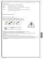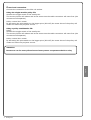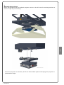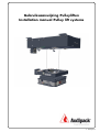
1
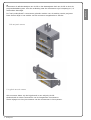
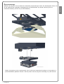
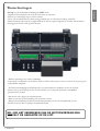
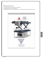
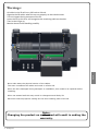
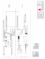
Gebruiksaanwijzing Pulleyliften
Installation manual Pulley lift systems
© Audipack
De Pulley liften zijn speciale liften die speciale aandacht vragen bij de installatie en gebruik.
De Pulley lift is een lift die automatisch de kabelverbinding verbreekt van de projector.
Het installeren, aanhelen van kabelverbindingen en instellen van de lift vragen om
vakmanschap en zorg aan het product.
Naast een juiste installatie is gebruik en beheer erg belangrijk.
Lees de onderstaande punten goed door en hanteer deze ook in toekomst.
Zorg dat de lift goed is geïnstalleerd.
Zorg voor voldoende serviceruimte om de lift heen
Zorg er voor dat de lift en connectoren goed zijn afgesteld.
Belast de lift nooit meer dan de toegestane belasting.
Onder de maximale belasting van de lift wordt verstaan:
-Projectormount
-projector
-plafondtegel / afwerking
Alle 3 deze elementen moeten binnen de maximale belasting vallen.
Indien de lift gebruikt wordt, laat de lift nooit afrollen of oprollen indien de kracht van de
hijskabels is afgenomen!
Werking van de lift:
De Pulley lift kan los toegepast worden van een eventuele schaarlift.
Indien een projector moet dalen worden automatisch de kontakten verbroken.
De projector daalt via 2 of 4 kabels naar beneden.
De maximale slag is fabrieksmatig begrenst.
Indien de lift in de onderste stand is, mag het beweegbare frame niet vastgehouden worden
tijdens dalen of heffen.
Als de projector weer omhoog beweegt, zal het beweegbare deel weer tegen de lift aanlopen.
De centreerpunten zorgen voor een exacte herpositionering van de projector.
Indien de centreerpunten in elkaar steken, loopt de motor nog iets door. Het ingebouwde
verenpakket in het beweegbare deel zorgen voor een permanente spanning en dus centrering
van het onderframe.
In deze positie kunnen de connectoren weer aangeheeld worden en zullen de
veiligheidshaken ook in positie komen.
© Audipack
Nederlands
Lees alvorens installeren:
De Pulley lift is een lift uitsluitend geschikt voor servicedoeleinden van de projector.
De projector zal alleen functioneren indien de lift in ingetrokken toestand word gebruikt.
De pulley liften kunnen in 4 verschillende modellen onderscheiden worden:
P2687
P2271
P1678
P2685
Pulley lift voor projectoren tot 20 Kg, 2 kabels
Pulley lift voor projectoren tot 45 Kg, 4 kabels
Combi Pulley lift met schaarlift voor projectoren tot 20 Kg, 2 kabels
(Geld ook voor de meerslags varianten)
Combi Pulley lift met schaarlift voor projectoren tot 45 Kg, 4 kabels
(Geld ook voor de meerslags varianten)
----Algemene montage
1.
Monteer de lift met de daarvoor bestemde montagepunten aan het plafond.
Zorg voor een stevige en stabiele montage. Draag er zorg voor dat alle
plafondbevestigingspunten gebruikt worden.
Houdt bij de montage in het plafond een vrije ruimte rondom de lift van ca 200 mm
voor service en onderhoudt doelen.
2.
Op de lift zijn 1 of 2 grijze besturingskasten gemonteerd (afhankelijk van uw model).
In de grootste doos zit de bediening voor de complete pulley lift. Afhankelijk van het model zit er
bij de combinatie liften 1 besturingsdoos voor de lift bij
Demonteer de deksels en vervang de reeds aangesloten bedieningskabels voor de definitieve
kabels.
De bediening van kabels dient met een eenvoudige potentiële schakelaar te geschieden.
Met bewegingsrichting een apart relais of schakelcontact. (zie aansluitschema).
Zie de bijlage voor het aansluiten van de liftbekabeling.
© Audipack
Nederlands
Gebruiksaanwijzing Pulley liften
Bij gebruik van een enkele pully:
Activeer de toggle-schakelaar van de kleine print (beveiliging / connectormotor).
De beveiliging van het systeem zal vrijkomen en de connectoren zullen zich van elkaar af
bewegen.
Bij het bedienen van de printschakelaars op de print kan vervolgens het liftdeel zakken.
Bij een gebruik van een combinatielift:
Pulley:
Activeer de toggle-schakelaar van de kleine print (beveiliging / connectormotor).
De beveiliging van het systeem zal vrijkomen en de connectoren zullen zich van elkaar af
bewegen.
Daalmotor:
Activeer vervolgens de daalmotor door op de “down” schakelaar te drukken op de grote
print. Het onderframe zal nu dalen tot op de hoogte zodat de projector gemonteerd kan
worden.
Schaarlift:
Activeer vervolgens de daalmotor door op de “down” schakelaar te drukken op de andere
grote print. Het onderframe zal nu dalen tot op de hoogte zodat de projector gemonteerd
kan worden.
Opmerking:
Let op dat er per motorbeweging een aparte bedieningsschakelaar of
aanstuurrelais gebruikt wordt.
Tevens het raadzaam per beweging een apart relais te gebruiken.
© Audipack
Nederlands
3.
Het bedienen en aansluiten.
Steek de stekkers van het systeem in het stopcontact in de juiste volgorde de systemen.
Beide motorbewegingen in de lift zijn door een volgordeschakeling aan elkaar gekoppeld.
Dit betekend feitelijk dat de connectoren pas kunnen verbinden indien de lift volledig in de
bovenste positie is.
In het beweegbare gedeelte van de lift is een vrijgavestift die ervoor zorgt dat er een
vrijgavesignaal gegeven wordt aan de connector-motor.
Indien deze stift niet goed op hoogte staat kan de connector-motor te vroeg starten of geheel
niet bewegen.
Stelbout
© Audipack
Nederlands
Opmerking:
De “early-make/break” connectoren gebruikt worden voor de aarding van de projector.
Deze dienen altijd in het midden van de connector aangebracht te worden.
Slede met female contacten
Vast gedeelte met male contacten
Alle connector-delen zijn los bijgeleverd in een zakje bij de lift.
Onderscheid de video-connectoren van de hoogstroom-connectoren.
Zie de bijlage voor het juist inzetten van de connectoren in het systeem.
© Audipack
Nederlands
4.
Demonteer de afschermbakjes van de lift en het beweegbare deel van de lift en sluit de
projectorbekabeling aan. Voor de verbinding naar de connectoren zijn krimptang en / of
soldeerbout benodigd.
Indien de projector juist is gemonteerd, kan de lift weer geactiveerd worden en de projector in
presentatiestand gebracht worden. Stel de positie van de projector eenmalig in op het scherm.
© Audipack
Nederlands
5.
Projectormontage.
Monteer de projector met de daarvoor bestemde projectorbeugel onder het beweegbare frame van
de lift. Gebruik alle mogelijke montagepunten die beschikbaar zijn Houdt rekening met de
maximale belasting van de lift (of liftcombinatie).
Het afstellen van de lift.
De pulley-liften zijn vanuit de fabriek reeds afgesteld op de motorlimieten en mogen niet
versteld worden.
Indien de schaarlift van de combinatie versteld dient te worden (inbouwpositie en
projectiehoogte), kan dit met de draaiknop versteld worden op de lift.
Hanteer de standaard plafondliften handleiding voor meer details.
© Audipack
Nederlands
6.
Neem de volgende stappen tot het uitlijnen van de centreerpunten.
1.
Zorg dat het onderframe los is van de lift, dus minimaal een afstand van 1000 mm.
2.
Los de montageschroeven met maximaal 2 gangen zodat de centreerpunten met de hand een
beetje kunnen schuiven. Doe dit alleen bij de bovenste centreerpunten.
3.
Laat de lift intrekken tot hij zelf stopt en richt de projector na.
4.
Borg vervolgens weer de schroeven van de bovenste centreerpunten.
© Audipack
Nederlands
7.
Uitlijnen centreerpunten.
Indien de plaatsing van het projector niet consequent is, is het mogelijk dat de centreerpunten
uitgelijnd moeten worden ten opzichte van elkaar.
-Let op, op alle elektrische bedrading kan 230 V staan.
-Organiseer de hijskabels van de lift alvorens deze te activeren.
-Dit kan op eenvoudige wijze verricht worden.
-Het is van noodzaak dat de kabels goed geordend zijn voor de juiste werking van de lift.
-Indien de kabels niet recht zijn opgerold dient de lift eerst geheel afgerold te worden, dan de kabels
rechtleggen en de lift omhoog laten komen.
-Haal de spanning nooit van de staalkabels.
Verkeerd op en afwinden van de kabels leidt tot slecht functioneren van het systeem en als gevolg een
verminderde veiligheid.
-Eventuele beschadigingen/afwijkingen die ontstaan tijdens de installatie en die van invloed
kunnen zijn op de werking van het systeem dienen, na overleg met de dealer, onmiddellijk
gerepareerd te worden.
-Sluit de lift aan volgens het aansluitschema.
-Denk er om dat op alle bedrading 230 V kunnen voeren.
-Monteer de bekabeling aan het bouwtechnisch plafond (niet het systeemplafond) op een
dermate wijze dat deze vrij blijft van draaiende delen.
NB.: BIJ HET VERBREKEN VAN DE MOTORVERZEGELING
VERVALT DE GARANTIE OP DE LIFT.
© Audipack
Nederlands
Waarschuwingen:
Thermische beveiliging
De plafondlift is voorzien van een zeer compacte en sterke motor.
Door de compacte bouw ontstaat er een warmteontwikkeling in de motorbuis van de lift.
De draaitijd van de motor bedraagt maximaal +/- 4 min. continu.
Na langer gebruik zal de motor vanzelf afslaan door de thermische beveiliging.
Laat de motor net zo lang afkoelen als dat de heftijd is voordat deze weer omhoog gaat.
De thermische beveiliging is niet een beveiliging waar bouwtechnisch of gebruiksmatig rekening mee
mag worden gehouden! Als de beveiliging intreed is dit een waarschuwing dat de lift overmatig wordt
gebruikt of overbelast wordt hetgeen kan leiden tot beschadigingen.
Bij het veelvuldig intreden van de beveiliging is het verstandig de oorzaak te achterhalen en een
oplossing daarvoor te zoeken.
Mogelijke reden activering thermische beveiliging:
De draaitijd is langer dan 4 min. achtereen (te hoge warmte-ontwikkeling).
Te hoge belasting
Bij het intreden zal de lift zelf uitschakelen, deze zal na een wachttijd van +/- 9-10 min weer
gebruiksklaar zijn.
© Audipack
Nederlands
Waarschuwing
Let op dat kledingstukken, haar , vingers en gereedschappen niet verstrikt
raken
Reed before installing:
The Pulley lift systems are special lift systems that require special attention and skills for
installation and use.
The Pulley lifty is a lift that is able to disconnect the projector cabling automatically before it’s
starts to decent.
The installation of the wires and connections must be done carefulley.
Next to the installation, service, maintanace and way of use is very important.
Read below items carefully.
Make sure the lift is proper and safe installed.
Be sure there’s anough space around lift lift in the ceiling for service and maintanance.
Be sure to adjust lift and connectors the right way.
Never overload the lift; this will have a negative affect on the system..
The max load is determined by:
-Weight projectormount
-Weight projector
-Weight ceiling finishing
When the lift is lowered, never hold on to the movable frame during movement.
The Pulley lift can be used in combination with a scissor lift system.
When a projector is being lowered, the cable connections will be disconnected automatically.
The projector wil decent by 2 or 4 cables. The maximum travel is factory set.
When the lift is lowered, never hold on the the movable frame during movement.
When the projector goes back up, it will centre with the centration cams. These make sure
the projector is aligned with the screen again..
When the movable frame is in upper position, the motor will run just a little bit further. The
build in springs will keep tension on the cables to make sure the cable connectors are
aligned.
The projector is ready to be used again.
© Audipack
English
How does the lift work?
The pulley lift systems are systems designed for servicing projectors, positioned at high altitudes in
buildings heights.
The pulley lift systems are available in 4 different models:
P2687
Pulley lift for projectors up to 20 Kg, 2 cables
P2271
Pulley lift for projectors op to 45 Kg, 4 cables
P1678
Combi Pulley lift systems with scissor lift up tot 20 Kg, 2 cables
(And the lifts with multiple strokes)
P2685
Combi Pulley lift systems with scissor lift up tot 45 Kg, 4 cables
(And the lifts with multiple strokes)
2.
On the lift, 1 or 2 control boxes are mounted (depending on the model).
On the single module pulley’s 1, on the combination lifts 2.
The large grey is for activating the safety device, cable connector management and the
pulley lift
The small one is for the scissor lift system.
Remove the covers and replace the current connected cables for the official ones.
In the print is shown how to connect. The control of the print must be done by potential free
relays or switched with a neutral middle position. (see attachment for the right way of
connecting).
© Audipack
English
General mounting instructions.
1.
Mount the lift level to the ceiling.
Use all mounting positions provided on the lift.
Keep a clearance around the lift in the ceiling of 200 mm.
This is reserved space for future maintenance and service.
3.
Control and connection.
Connect the connectors to the 230 volt outlets.
Using the single module pulley lift:
Activate the toggle switch of the small print.
The security hooks will release and at the same time the cable connection will come free (the
connectors will separate).
Pulley vertical drive motor:
By activating the print switch on the bigger print (261125) the motor drive of the pulley will
rotate and lower the projector mount.
Using a pulley combination lift:
Pulley:
Activate the toggle switch of the small print.
The security hooks will release and at the same time the cable connection will come free (the
connectors will separate).
Pulley vertical drive motor:
By activating the print switch on the bigger print (261125) the motor drive of the pulley will
rotate and lower the projector mount.
Attention:
English
Be sure to use for every direction and every motor a separate switch or relay
© Audipack
Remark:
The pulley lift motor actions are secured.
This means the connectors will only be connected when the lift is in upper position.
It might be possible to readjust the activation switch. When the lift is in upper position, a pin will
activate a release switch. The switch is for activating the connector motor drive.
By setting the right height of the pin, the exact time of release can be set.
English
Pin
© Audipack
4.
Undo the connector covers of the lift and remove the connectors.
Connect the projector cables to the connector and place the female pieces tot the motorized
part (!).
The early make-brake pieces must be used for grounding.
and should be in the centre of the connector.
See the attached drawing for the right connector configuration.
English
Female contacts
Male contacts
All connector parts are supplied separately in a bag with the lift.
Organize the power connectors from the signal connectors!
When the connectors are removed, carefully test the fitting in
the lift (and each other) to avoid connector damage.
© Audipack
English
5.
Mounting the projector
Mount the projector with an Audipack projector mount to the lift. Use all mounting positions to
secure a right way of mounting.
When the projector is mounted, the lift can be activated again and bringing the projector to
presentation height
© Audipack
6.
Adjusting the scissor lift.
English
The pulley lift system are preset in the factory.
These settings may not be disturbed.
For adjusting the scissor lift please refer to the manual instruction of that lift system.
© Audipack
Warning
Beware of clothing fingers and long hair when working on the lift!
Thermostatic security
All lift systems are equipped with tubular motor with a max. running time of +/- 4 min.
continuously.
When using the motor longer, will result that the motor will stop automatically.
When this happened a cooling period of 9-10 min is obligated.
WHEN THE LIFT WILL STOP, CAUSED BY THERMOSTATIC STOP,
THIS IS A WARNING THAT THE LIFT IS USED TO LONG or is in overload.
English
By doing this very often this may result in a damaged and burned motor.
Warranty conditions.
The warrenty poriod of the lift is 12 months.
It is obligated to check the llift and connection every 6 months. A record should be kept.
See the general terms of delivery for warranty conditions
© Audipack
7.
Lining out the centre points of the pulley lift.
When the accuracy of replacement of the pulley is not good, the centre points of the lift may
need to be reset.
1.
Lower the projector plate for at least 1000 mm. And take away the power of the lift (230 volt)
2.
Loosen the mounting screws of of the centre points on the projector frame. This will give a little
play to slide the centre points.
3.
Let the lift go up and let it make the centre points linig out on each other.
4.
Fasten in the situation the centre points again.
© Audipack
English
Take following measures to reset the centre points.
Warnings:
English
All cables in the lift will carry 230 volts or 24 volt.
Organize the lift cables when the are not properly on the tubular motor.
This can happen during transport of the lift.
Lower the lift in this case, and reorganize the remaining cable on the tube.
Then let the lift go up.
Monitor these kind of handling carefully.
Never take away the physical tension of the cables.
This may unorganise the cables and result in a faulty lift.
When the lift is damaged during transport or installation, this needs to be repaired before
installing.
When not treated well this may result in a dangerous and faulty lift.
Mount all external projector cabling etc free from rotating parts of the lift.
Note.:
Changing the product un authorized will result in ending the
warranty.
© Audipack
Audipack's general conditions of sales and delivery apply to all of Audipack's
deliveries. These conditions can be downloaded from Audipack's website,
www.audipack.com, or will be sent by post on request.
Audipack
liefert
ausschließlich
unter
die
allgemeine
Verkaufund
Lieferungsbedingungen von Audipack. Diese Bedingungen sind zum downloaden
verfügbar auf die Webseite von Audipack, www.audipack.com, oder werden
Ihnen auf Anfrage per Post gesendet.
Alle leveringen geschieden uitsluitend volgens de Algemene Verkoop- en
Leveringsvoorwaarden van Audipack. Een afschrift hiervan kunt u downloaden
van de website van Audipack, www.audipack.com, of wordt u op aanvraag
gestuurd per post.
Les conditions de vente et de livraison de Audipack s'appliquent à tous les
livraisons de Audipack. Cette conditions sont disponible sur le site internet de
Audipack, www.audipack.com, où seront envoyé par poste sur demande.
AUDIPACK
Industriestraat 2-4
2751 GT Moerkapelle
the Netherlands
Tel: +31(0)795931671
Fax: +31(0)795933115
Email: [email protected]
www.audipack.com
Audipack reserves the right to make changes in specifications and other information contained in this document without prior written notice. The
information provided herein is subject to change without notice. In no event shall Audipack be liable for any incidental, special, indirect, or consequential
damages whatsoever, including but not limited to lost profits, arising out of or related to this manual or the information contained herein, even if
Audipack has been advised of, known, or should have known, the possibility of such damages.
© Audipack