1
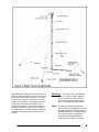
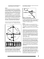
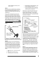
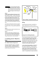
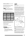
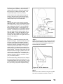
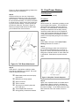
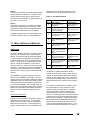
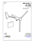
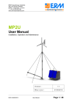
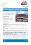
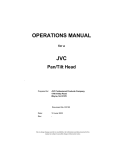
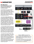
Version 2.0
July 2001
BWC XL.1
Tilt.Tower
Tilt
Installation Manual
9 m (30 ft) Tilt.Tower
13 m (42 ft) Tilt.Tower
19 m (64 ft) Tilt.Tower
25 m (84 ft) Tilt.Tower
32 m (104 ft) Tilt.Tower
Bergey Windpower Co., Inc.
2001 Priestley Ave.,
Norman, OK 73069 USA
Telephone: (405) 364-4212
Fax: (405) 364-2078
E-mail: [email protected]
Web: www.bergey.com
Please Help Us Improve This Manual
We would be very interested to hear any comments you might have on this
new installation manual. We are particularly interested in learning of mistakes or omissions and subjects that are unclear. Please call, fax, or e-mail
and direct your comments to Steve Wilke in Customer Service. Thank you
very much for your assistance.
Tel: 866-237-4397 (toll-free in U.S.)
Tel: 405-364-4212
Fax: 405-364-2078
e-mail: [email protected]
1
BWC Tilt-up Tower & BWC XL.1
INSTALLATION MANUAL
Table of Contents
1.
2.
Overview ……………………...
Safety …………………………
2
3
3.
4.
5.
6.
7.
Cautions and Warnings ……..
Components ………………….
Anchors and Base …………...
Tower Assembly ……………..
Initial Tower Raising ……….
3
3
3
6
10
8.
9.
10.
11.
Tower Lowering ……………...
XL.1 Wind Turbine …………..
Final Tower Raising ………..
Miscellaneous Reference Material …………………………...
11
12
15
16
1. Overview
The Tilt.Tower is the factory recommended tower
for the Bergey XL.1 tower because it combines
cost-effectiveness and ease of installation. Over
the long-term the Tilt.Tower will also reduce “total
costs of ownership” by making it easier for owners
to inspect, provide preventive maintenance (particularly in corrosive environments), and perform
repairs to the XL.1 wind turbine.
the guy wires along the tilt-axis will change appreciably between the tilted-up and tilted-down positions. If the anchors are lower than the base the
tension in the cable(s) can become excessive. If
the anchors are higher than the base the cable(s)
can become too loose to provide proper stability
of the tower sections. When installing in sloped
terrain, the Tilt.Tower should always tilt-down in
the upslope direction.
After assembly of the tower, wind turbine, and
tower wiring on the ground, the tower and turbine
are tilted-up to the vertical position using a winch
(not supplied) or a vehicle. A winch is preferred
because of the greater control they afford. It is
possible to raise the 30 ft. (9 meter) tower and
turbine without a winch, but it takes 3-4 crewmembers to do it safely. The towers are provided
with a lever arm, called a gin-pole, which runs
from the base to one of the guy anchors. The ginpole converts the pulling force on the pull-up rope
or cable into a lifting force on the turbine and
tower. Without the gin-pole it would be virtually
impossible to raise the tower.
The Tilt.Tower kit includes all of the components
and fasteners required to assemble and ground
the tower. The tower can be installed without concrete work in areas with good soil strength and no
rocks (that would impede the screw-in guy-wire
anchors). In weak or rocky soils the use of concrete to fix the anchors is required. Proper
grounding (or “earthing”) is an important element
in protecting the system from lightning damage.
As shown in Figure 1, the tower is guyed in four
directions. The tower is guyed at vertical intervals
of approximately 20 ft (6 meters). The Tilt.Tower
is best installed on level ground, but can be installed on slopes or uneven terrain provided that
the base and the anchors on the tilt-axis can be
kept fairly level. If this is not done, the tension in
Figure 1, 9 m (30 ft) Tilt.Tower
2
2. Safety and Quality Assurance
The following recommendations should be carefully observed as part of any tower raising and
lowering, and during the tower siting process. In
particular, the safety of the crewmembers must be
placed ahead of all other considerations. Some of
the following warnings or cautions have been
highlighted in the appropriate section of the manual.
1. DO read and follow the Tower Installation
Manual.
At several points in the manual items of special
interest or significant impact are highlighted by
one of the following notices.
Warning:
Hazards or unsafe practices that
could cause personal injury or death.
Caution:
Hazards or unsafe practices that
could cause product damage.
Note:
Significant points of interest
2. DO NOT climb the tower.
3. DO NOT erect the tower within 1 1/2 times the
tower height of electric power lines.
4. DO NOT place guy anchors near roads, driveways, or normal paths for vehicles.
5. DO NOT permit unnecessary persons on the
tower site while the tower is being raised or
lowered.
6. DO NOT use a tractor or other vehicle to erect
the tower without exercising extreme caution.
7. DO determine the soil type at your site and
install the correct anchoring.
8. DO place tower anchors according to the anchor manufacturer’s recommendations.
9. DO properly ground the towers electrically.
10. DO thoroughly understand the tower erection
procedure before beginning the installation.
The Tilt.Tower is cost-effective, safe, and convenient; but the forces involved in raising and lowering are very large. Inadequate attention to proper
rigging and procedures can lead to destruction of
the equipment and/or serious injury. DO NOT cut
corners or get into a hurry.
3. Cautions and Warnings
This manual contains important information on the
installation of your Tilt.Tower, XL.1 wind turbine,
and PowerCenter controller. We strongly recommend that you read and follow the instructions
contained in this manual.
4. Components
The major components for the tower kits are
shown in Figure 2. This figure shows a 25 meter
(84 ft) tower, which like the 19 m (64 ft.) and 32 m
(104 ft.) towers uses larger diameter and longer
tower tubes and has a ginpole that is shorter than
the guy radius. The 9 m (30 ft.), like the one
shown on the cover of this manual and in Fig. 1,
and the 13 m (42 ft.) towers use smaller and
shorter tubes and have a ginpole that extends out
to the anchor point.
5. Anchors & Base Plate
Please review the Anchoring Reference section in
Section 11 before proceeding further. Different
soil conditions may require different anchoring
methods to ensure proper strength.
Tools Required:
5-6 wood or metal stakes
Hammer
Sledge-hammer
100 ft. tape measure
2 1/2 ft long x 1” –1 1/2” diameter metal bar
or pipe
Shovel (if ground is too hard for screw-in anchors)
9/16” box-end wrench
12” crescent wrench
Procedure:
Step 1:
Mark the ground location for the tower base plate,
guy anchors, and the lifting anchor for the gin pole
(not required for 30’ and 42’ towers). The appro-
3
priate dimensions and ground layout are shown in
Figure 3. Make sure that you have sufficient room
for the tower and turbine to tilt down. If you plan
to mount solar modules on the tower we recommend that the ginpole be oriented towards South
in the Northern Hemisphere and North in the
Southern Hemisphere. If the site is not level, try
to position the tower so that it will be lowered in
the uphill direction. Check the diagonal distance
between anchor points to ensure that they are
“square”.
Warning:
The tower must not be erected
within 1 1/2 times the tower height of
electric power lines. Most overhead
power lines are not insulated, so they
pose a life-threatening shock hazard.
Note: The side guy anchors and the base
plate must be on a straight line to insure
adequate cable tension during raising or
lowering operations. If exact placement
of an anchor point is not possible, it
should be moved outward from the
base rather than inward. Try to keep
4
the side anchors and the base plate at
approximately the same elevation
Step 2:
Screw in the four Guy Anchors at ~ 45 degrees
pointing towards the tower base stake, leaving 4
inches to 8 inches (10 cm - 20 cm) above ground,
as shown in Figure 4. When finished the eye at
the end of the anchor rod should have its eye oriented vertically, as in Fig. 4. A ~ 2 1/2 ft. metal
bar or heavy wall pipe, ~ 1 - 1 1/2 inch in diameter, will be necessary to develop the high torque
required to screw the anchors in. The 4’ ground
rods may be used, but they are awkward because
they are too long. The screw anchors for the 9
and 13 m towers have a 4” helix and are 1.37 m
(54”) long. The screw anchors for the taller towers have a 6” helix and are 1.68 m (66”) long.
On the 19, 25, and 32 m towers the Ginpole Anchors are screwed in at a ~ 45 degree angle also.
be necessary to dig holes, insert the anchors and
fill the hole with concrete.
Towards Center Pad
~ 45 Degrees
~ 150 mm (6“)
Ground level
Screw-in Anchor
Figure 4, Anchor Angle
For weak or problematic soils it may be necessary
to use concrete for the anchors or use an alternate anchoring method. These topics are covered
in Section 11, under Anchoring.
Step 3:
For most installations the base plate will sit directly on the ground. This is actually the preferred
configuration. A concrete base is only needed
when the soil strength is very low, such as sand or
marsh.
Tower
Uphill Guy Anchor
g
ia
D
on
Assemble the four piece base plate with the galvanized bolts supplied with the kit as shown in
Figure 5. Install the base plate with its upturned
flanges aligned with the tower lay-down direction.
Sink the down turned edges into the soil. Pound
in the 4 ft (1.2 m) copper-clad ground rod through
one of the two ¾” holes in the base plate using a
sledgehammer. Leave ~ 4 inches (10 cm) of rod
above the Base Plate.
n
ta
is
D
al
ce
Guy Radius
Side Guy
Anchor
Side Guy
Anchor
Base
Plate
Ginpole
Anchor
Distance
Ginpole
Anchor
Downhill Guy
Anchor
Layout Dimensions in Feet
Tower
Height
30 ft.
42 ft.
64 ft.
84 ft.
104 ft.
Guy
Radius
19 ft.
19 ft.
35 ft.
50 ft.
60 ft.
Ginpole
Diagonal Anchor
Distance Distance
26.8 ft.
N.A.
26.8 ft.
N.A.
49.5 ft.
20 ft.
70.7 ft.
29 ft.
84.6 ft.
29 ft.
Layout Dimensions in Meters
Tower
Height
9m
13 m
19 m
25 m
32 m
Guy
Radius
5.8 m
5.8 m
10.7 m
15.2 m
18.3 m
Diagonal
Distance
8.17 m
8.17 m
15.1 m
21.6 m
25.8 m
Ginpole
Anchor
Distance
N.A.
N.A.
6.1 m
8.9 m
8.9 m
Figure 3, Anchor Layout
Turn the screw anchor clockwise so that the auger
bit bites into the ground. One hint for getting the
screw anchor started is to press the auger part
into the ground with your foot while turning. If the
anchors cannot be screwed in due to rocks, it may
When using a concrete base for the tower we recommend a base that is roughly 60 cm x 60 cm x
30 cm deep (2 ft x 2 ft x 1 ft deep), with several
pieces of steel reinforcing bar placed horizontally.
The Tilt.Tower Base Plate must be secured to the
concrete using two 5/8” hex head bolts (not supplied) or concrete anchor bolts (not supplied) installed through the ¾” holes normally used for the
ground rods.
You can either cast hex bolts into the concrete or
pour the concrete pad and install anchor bolts after the pad has cured. Drilling the pad for anchor
bolts will generally require the use of a hammer
drill. For cast in bolts, we recommend two 6” long
galvanized 5/8” diameter bolts with ~ 2 ½” of the
threaded end sticking up above the concrete. The
bolts should be centered on the pad and be
5
spaced 15 ¼” apart. Note the tower tilt alignment
direction required in Figure 5.
For non-concrete installations the channel plate
that faces towards the gin-pole anchor should be
assembled in the extended position, as shown in
Figure 5. When being bolted to a concrete pad
the channel plate should be assembled in the retracted position. Securely bolt the Base Plate to
the concrete pad. Install the ground rods adjacent
to the concrete pad.
Galvanized
bolts (6 places)
Top View
3/4“ holes for ground
rods or concrete
anchors
Ginpole
direction
Tower tiltdown
direction
Not used
Bolt hole for
tower tube
Move this
channel
in when
mounting
on concrete
Bolt hole for
ginpole tube
Side View
Figure 5, Base Plate Assembly
6. Tower Assembly
Tools Required:
3/4” box-end wrench
½” box-end wrench
12” crescent wrench
7/16” nut driver or box-end wrench
Tape measure
Electric drill
7/32” drill bit
3/8” socket drive
Electrical tape
Procedures:
9 m (30 ft) and 13 m (42 ft) Towers:
These two heights use 89 mm (3.5”) tubing that
comes in nominal lengths of 2 m (6.5 ft). The
taller XL.1 towers (19, 25, & 32 m) use tubing that
is larger in diameter and longer.
Step 1:
Bolt the base tower section to the base plate using a 1/2” diameter x 5” long bolt and nut through
the hole drilled in the flared end of the base section. Use the lower hole in the center of the long
base plate, as shown in Figure 5.
Note:
If the power leads are to be carried inside the tower, as is recommended,
they should be installed as the tower is
being assembled. See Section 9 for
wire size recommendations.
Step 2:
On a 30 ft (9 m) tower, add three more 2 m (6.5 ft)
sections. Add the shorter 1.4 m (4.5 ft) turbine
mounting section, making sure that it is firmly
seated. This is a highly stressed joint and requires reinforcement with three self-tapping ¼”
screws, as shown in Figure A below. If these fasteners are not added the joint will loosen over
time. To install the ¼” fasteners, drill a 7/32” pilot
hole ~ 1” above the bottom of the top section.
Then use a 3/8” socket drive to screw in the ¼”
self-tapping screw.
The other two screws are spaced 9.8 cm (3 7/8”)
in both directions around the outside of the tube
from the first fastener. This measure will place
them equally spaced at 120 degrees. Repeat the
process of drilling and screwing in the ¼” fasteners.
Slide on the guy ring over the top of the tower
while the spooled guy wire sets are attached. Do
not unspool the guy wires at this stage. There is
only one set of guy wires on the 9 m (30 ft) tower.
On the 13 m (42 ft) tower, add three 2 m (6 ft)
sections to the base section for a total of ~ 8 m
(26 ft). Slide on the first guy ring (Labeled 20 ft
level) over the top of the fourth tube while the
spooled guy wire set are attached. Do not unspool the guy wires at this stage.
The procedures are somewhat different for the 9
and 13 meter towers and the taller 19 – 32 m towers:
6
Make sure that the guy wire labeled “40 ft level
lifting” is on the top. There is a red tag on the lifter
eye of this wire.
You can now proceed to Step 7.
Top 1.4 m
Section
19 m (64 ft), 25 m (84 ft), and 32 m (104
ft) Towers:
1“ (25 mm)
1/4“ Self-Tapping
Screws, 3 equally
spaced around the
tube (120 degree
spacing)
Drill 7/32“ (5.6 mm)
pilot hole before
inserting screw
Upper 2 m
or 3 m Section
Figure A, Top Section Fasteners
Step 3:
Slide the guy ring all the way down the tube to the
flared connection where the tubes join. Make
sure that the guy ring “ears” are facing towards
the base plate. The ring will rest against the
flared diameter of the tube.
Make sure that the guy wire labeled “20 ft level
lifting” is on the top. There is a red tag on the lifter
eye of this wire.
Step 4:
In the case of a 13 m (42 ft) tower, add two 2 m
(6.5 ft) sections. Then add the shorter 1.4 m (4.5
ft) turbine mounting section. Secure the top section with the three ¼” self-tapping fasteners as
described in Step 2 and shown in Figure A.
Slide on the second guy ring (Labeled 40 ft level)
over the top tube while the spooled guy wire set is
attached. Do not unspool the guy wires at this
stage.
Slide the guy ring all the way down the tube to the
flared connection where the tubes join. Make
sure that the guy ring “ears” are facing towards
the base plate. The ring will rest against the
flared diameter of the tube.
These three heights use 114 mm (4.5”) tubing that
comes in nominal lengths of 3 m (10 ft). They
also have a gin-pole, which is shorter than the guy
radius, requiring a fifth screw-in anchor.
Step 1:
Bolt the base tower section to the base plate using a 1/2” diameter X 6” long bolt and nut through
the hole drilled in the flared end of the base section. Use the lower hole in the center of the long
base plate, as shown in Figure 5.
Note:
If the power leads are to be carried inside the tower, as is recommended,
they should be installed as the tower is
being assembled. See Section 9 for
wire size recommendations.
Step 2:
Add two 3 m (10 ft) sections to the base section
for a total of 9 m (30 ft). Slide on the first guy ring
(Labeled 20 ft level) over the top of the third tube
while the spooled guy wire set are attached. Do
not unspool the guy wires at this stage.
Slide the guy ring all the way down the tube to the
flared connection where the tubes join. The ring
will rest against the flared diameter of the tube.
Make sure that the guy ring “ears” are facing towards the base plate.
Make sure that the guy wire labeled “20 ft level
lifting” is on the top. There is a red tag on the lifter
eye of this wire.
Step 3:
Add two more 3 m (10 ft) sections and slide on the
40 ft level guys. Make sure that the guy ring
“ears” are facing towards the base plate. Slide
the guy ring all the way down the tube to the
flared connection where the tubes join. The ring
will rest against the flared diameter of the tube.
Do not unspool the guy wires at this stage.
7
Make sure that the guy wire labeled “40 ft level
lifting” is on the top. There is a red tag on the lifter
eye of this wire.
scribed in Step 2 (in previous section, for the 9 m
tower) and shown in Figure A. Then slide on the
100 ft level guy ring.
Step 4:
On a 19 m (64 ft) tower, add one more 3 m (10 ft)
section. Then add the shorter 1.4 m (4.5 ft) turbine mounting section. Secure the top section
with the three ¼” self-tapping fasteners as described in Step 2 (in previous section, for the 9 m
tower) and shown in Figure A.
Make sure that the guy ring “ears” are facing towards the base plate. Slide the guy ring all the
way down the tube to the flared connection where
the tubes join. The ring will rest against the flared
diameter of the tube. Do not unspool the guy
wires at this stage.
On the 25 m and 32 m towers, add two more 3 m
(10 ft) sections and slide on the 60 ft level guy ring
and wires.
Make sure that the guy ring “ears” are facing towards the base plate. Slide the guy ring all the
way down the tube to the flared connection where
the tubes join. The ring will rest against the flared
diameter of the tube. Do not unspool the guy
wires at this stage.
Make sure that the guy wire labeled “100 ft level
lifting” is on the top. There is a red tag on the lifter
eye of this wire.
Step 7:
Roll out the side guy wires to the side anchors.
Use a screwdriver or small diameter rod through
the center of the wire spool as an “axle”. Let the
wire unwind as you walk out to the anchor point.
Note:
On the 19 m and taller towers, the guy
wires marked for “Lifting” must be on
the upper side of the horizontal tower
sections. The guy wires marked “Lifting” have an eye swaged to the cable.
This eye is clipped to the top of the gin
pole. These guy wires serve as the lifting wires until the tower is fully erected.
Note:
Guy wires must be rolled out to the anchors, not let out from a coil held in the
hand or from the side of the spool.
These latter two methods will allow the
wire to become severely twisted and
stressed, making it very difficult to handle.
Make sure that the guy wire labeled “60 ft level
lifting” is on the top. There is a red tag on the lifter
eye of this wire.
Step 5:
On a 25 m (84 ft) tower, add one more 3 m (10 ft)
section. Then add the shorter 1.4 m (4.5 ft) turbine mounting section. Secure the top section
with the three ¼” self-tapping fasteners as described in Step 2 (in previous section, for the 9 m
tower) and shown in Figure A. Then slide on the
80 ft level guy ring.
On the a 32 m (104 ft) tower, add two more 3 m
(10 ft) sections and slide on the 80 ft level guy ring
and wires.
Make sure that the guy ring “ears” are facing towards the base plate. Slide the guy ring all the
way down the tube to the flared connection where
the tubes join. The ring will rest against the flared
diameter of the tube. Do not unspool the guy
wires at this stage.
Make sure that the guy wire labeled “80 ft level
lifting” is on the top. There is a red tag on the lifter
eye of this wire.
Step 6:
On a 32 m (104 ft) tower, add one more 3 m (10
ft) section. Then add the shorter 1.4 m (4.5 ft) turbine mounting section. Secure the top section
with the three ¼” self-tapping fasteners as de-
Step 8:
When the guy wires are rolled out to all the anchors, check to insure that the tower forms a right
angle with the line joining the side anchors and
the base plate. Check also that the front and rear
anchors and the lifting anchor are in line with the
tower.
Caution: Extra care must be taken while raising the tower if the anchor placement is
not perpendicular to the tower, or if the
side anchors are not at the same elevation, or if the side anchors and base
plate are not in a straight line. Any of
these conditions will effect the guy wire
tension as the tower is raised. Tension
8
must be adjusted periodically as the
tower is raised.
4.
5.
Step 9:
Slide three wire rope malleable clips (supplied in
the guy set box) onto each guy wire end. Thread
the guy wire end through the anchor rod eye,
double back and slide through the first wire rope
malleable clip.
The guy wires are wrapped around the anchor
eye as shown on the anchor detail in Figure 6.
Place the wire rope clips on the wire so that the
forged, grooved part cradles the wire coming from
the tower (the “tension side”) and the “U-bolt” part
clamps down on the end-most section of the wire.
Leave a little slack in the guy wire. Snug up the
wire rope clip nuts using a 7/16” nut driver, but not
too tight - it may be necessary to adjust them during the tilt-up procedure. Let the other two clips
remain loose until the tower has been erected and
leveled.
When bolting gin pole to base plate, pass
bolt through loop in safety wire.
When assembling gin pole tie top brackets at the outer end of the gin pole, pass
bolt through loop in safety wire.
The 9 and 13 m (30’ and 42’) towers use a 6 m
(20 ft) gin-pole, made up of three 2 m sections.
The 19 m (64’) tower uses a ~ 20 ft. gin pole,
made up of two 10 ft. sections. The 25 and 32 m
(84’ and 104’) towers use a ~ 30 ft gin pole, made
up of three 10 ft sections.
Malleable Clip
Figure 7, Ginpole Safety Wire
Assembly
Note: 6“ ”Tripleye”
anchor for 19 - 32 m
towers shown
Figure 6, Guy Wire Attachment
Step 10:
Referring to Figure 5, the gin pole will attach to
the base plate with a ½” x 6” bolt. The ginpole is
assembled in the same direction as the tower itself, with the ginpole resting on top of the tower
sections. The following procedure integrates the
assembly of the gin pole safety wire (see Figure
7), which will keep the gin pole from coming apart
when the load direction changes during tower
raising:
1.
2.
3.
Assemble gin pole – align holes at each
end
Slide safety wire inside gin pole.
Assemble gin pole on top of tower.
Make sure that the bracket bolt in the end section
of the gin pole is aligned as shown in Figure 7.
Bolt the tie top brackets to the end section. Attach
the snap links to the tie top bracket with shackles.
A snap link is a heavy galvanized steel or
stainless steel loop with a spring-loaded gate or
opening side bar. A shackle is a heavy galvanized steel U-shaped ring with a heavy pin that
when assembled forms a D-shaped connector.
Be sure that the snap link opens down and away
from the base plate. This will allow the lifting guy
wires to be clipped and unclipped in the correct
order.
Step 11:
Roll out each level of the lifting guy wires and attach each of the swaged-on lifting eyes to the
snap links shackled to the bracket at the end of
the gin pole. The top guy wire attaches to the
forward snap link. The lower guy(s) are clipped to
the second snap link, the lowest guy wire first.
Make sure that the guy wires are not twisted. The
9
free ends of the remaining guy wires will be attached to the forward anchor after the tower is
erected. Keep the wires well organized so this will
be easy to do.
Step 12:
Attach the two yellow polypropylene ropes to the
top of the gin pole. Run one of the ropes to each
of the side anchors. The ropes prevent the gin
pole from falling sideways when vertical and center it as the tower is being raised.
Step 13:
Attach the cable from the lifting device to the gin
pole tie top bracket with a shackle from the hardware kit. Electric or hand winches may be used.
The pull-up forces (including the XL.1 turbine) and
the pull-up cable lengths are given below:
Pull-up
Cable
Travel,
meters (ft)
Height,
meters
Height,
feet
Pull-up
Force, kgs
(lbs)
9
30
160 (350)
9 (29)
13
42
250 (550)
9 (29)
19
64
340 (750)
13.1 (43)
25
84
520 (1,150)
13.1 (43)
32
104
700 (1,550)
13.1 (43)
These loads are static loads. Bouncing or shock
loading can cause higher momentary loads. We
recommend using at least 3/16” steel wire rope for
the lifting. We also recommend a 2:1 pulley block
arrangement to reduce the line tension for the 25
and 32 meter towers. A 2:1 pulley block will cut
the pull-up force in half. The pulley block is attached to the ginpole shackle or snap-link. Please
remember that using a 2:1 pulley will double the
pull-up cable travel to 27 m (86 ft).
Warning:
If a winch is used we strongly
recommend that a worm-gear type be
used and that a spur-gear type be
avoided. A worm-gear winch is inherently self-locking and cannot free-spool
like a spur-gear type winch.
Bergey Windpower offers manual and electric
winch kits that are rigged and ready to go. Contact your dealer or Bergey Windpower for information and pricing.
Caution:
If using a tractor or truck, extreme
care must be exercised. Use a pulley
block at the lifting anchor. Never attach
a cable from a truck/tractor directly to
the gin pole end. Proceed slowly and
smoothly.
Step 14:
Walk the gin pole toward the vertical position
while taking in the slack with the lifting device.
When the gin pole is nearly vertical, all the lifting
wires should be tight. If using a drum winch, try to
guide the cable onto the drum so that it is distributed evenly across the surface of the drum.
Step 15:
Use some tape to secure the tower electrical wiring at the top end of the tower so that it will not
slide down the tower when the tower is raised.
Step 16:
Lift the tower 1.2 m to 1.8 m (4 ft to 8 ft) above the
ground to check the operation of the lifting device
and the security of the lifting and guy cables. The
side guy wires must be tended to prevent the
tower from bowing or falling off to one side or the
other. In addition to checking the security and
adjustment of the guy wires, check the lifting anchor for movement. If the gin pole anchor will not
hold, the soil is too poor for this type of anchor or
the depth of the anchor was insufficient. The
maximum lifting force is experienced when the
tower is first lifted from the ground.
Warning: Do not work under or near the
tower while it is being lifted. Do not
work under or near the tower when it is
off the ground, unless it is resting on
blocks or is fully guyed.
Step 17:
Lower the tower and make any necessary adjustments to the guy wires or anchors. Roll out the
guy wires that will be attached to the back anchor
located under the tower pole.
7. Initial Tower Raising
At this stage, an initial tower raising without the
wind turbine in place is recommended. It will insure that all the cables and anchors are secure,
that the lifting procedure is satisfactory, and will
10
allow the back guy wires to be attached and adjusted. The sequence is shown in Figure 8.
Note: The guy wires can be pulled in by one
person when the winch is stopped.
Brute force is not required.
Tools Required:
7/16” nut driver
Procedure:
Step 1:
o
o
Start lifting the tower 10 to 20 at a time. Monitor
the side guy wires and the yellow gin pole ropes
carefully. They may become either loose or tight
if the site and the anchor points are not perfectly
level. Although there must be some tension in the
wires at all times to provide side support for the
tower, there must always be visible slack in the
guy wires. If no slack is visible, the tension is too
great. Over-tension may cause failure of the
wires, the anchors, or the tower. For further information, refer to the section on SLACK at the
end of the instructions.
Step 2:
o
Continue lifting and adjusting until the tower is 45
o
to 60 toward the vertical. Attach the set of back
guy wires to the back anchor. The back wires
should be walked over to the side anchors to get
an approximate length prior to attachment.
Step 3:
As the tower approaches vertical, it is important to
maintain tension on the back guy wire set. This
should be done by standing to one side of the anchor, not directly under the tower, pulling on ropes
attached to the guy wires. All back guy wires
should be held, allowing the raising device to pull
against the tension until the tower is vertical or the
gin pole is on the ground.
Note: The tower will lift easily at this point.
Very little force is required to lift the
tower into its final position.
Step 4:
Check the side guy wire tension for a moderate
degree of slack, corresponding to a wire pull of
about 23 kilograms (50 pounds). Check the security of the wire rope clips.
Failure to install the Ginpole
Safety Wire can lead to ginpole
separation !
Maintaining tension on the lifting cables with the
raising device, use a carpenter’s level on the base
tube to adjust the guy wires until the base tube is
vertical. Insure that the tower is straight by sighting up the tower while the final guy adjustments
are being made.
For this initial lift, it will not be necessary to transfer the lifting guy wires from the gin pole to the
forward anchor.
Figure 8, Tower Tilt-up Sequence
Adjust the cable tension as required using the
wire rope clips. Work slowly. Fast uneven
movements tend to make the tower swing or waver. Try to work smoothly and insure that those
people tending the cables are able to follow along
with the tower raising process.
Caution: Be sure that communication between all members of the lifting team is
clear and concise.
8. Lowering the Tower
The procedure is just the reverse of raising the
tower, although certain precautions must be
taken.
Step 1:
If the raising process has indicated that the tension of the side guy wires will vary as the tower is
being lowered, it is important that the side guy
wires be tended to avoid excessive tightening or
slackening.
11
WARNING: At no time during the lowering
operation should personnel, vehicles, or
other equipment be located where they
could be hit by the tower or the side guy
wires. Determine the boundaries of the
potentially dangerous area and keep it
clear.
Step 2:
Tension must be applied to the back guy wires to
pull the tower away from the raising device as it
begins letting out cable. In order to clear the danger area, it will be necessary to apply the tension
through ropes attached to the guy wires. The
ropes should be attached above the back anchor
and should be long enough to insure that personnel are located well beyond the point where the
top of the tower will touch the ground when lowered. Pull as required to keep tension on the guy
wires.
As the tower is lowered and reaches an angle beo
o
tween 60 and 45 , it will no longer be necessary
to maintain tension on the guy wires opposite the
winch.
Step 3:
Set the tower down on blocks placed about every
6 m (20 ft) along the tower.
Step 4:
Ground the tower base by installing the brass
“acorn nut” to one of the ground rods and attaching one end of the 1/8” bare copper grounding
wire. Attach the other end of the grounding wire,
using a small loop, to the ½” tower pivot bolt.
9. Installing the XL.1 Wind Turbine
XL.1 Wind Turbine Components
The major components of the XL.1 wind turbine
are shown in Figure 9. Installing the turbine requires connecting it to electrical wiring to the
PowerCenter controller and then assembling the
turbine at the top end of the tower.
Powerhead
Tail Fin
Nacelle
Alternator
Blades
Spinner
Tail Boom
Tower
Mount
Figure 9, Major Components of the XL.1
Wiring
The basic electrical schematic for the BWC XL.1
battery charging system is shown in Figure 10.
Alternator
DC Wire Run
Rectifier
(on turbine)
PowerCenter
Figure 10, XL.1 Wiring Schematic
The wind turbine alternator produces a 3-phase
AC, which is rectified into DC up in the nacelle. A
two (2)-conductor wire is needed between the
wind turbine and the PowerCenter controller. The
PowerCenter has a DC circuit breaker for the wind
turbine input, so no fused-disconnect switch is
required at the base of the tower (as is recommended for the other BWC wind turbines).
In some cases it will be possible to provide direct
point-to-point wiring between the XL.1 wind turbine and the PowerCenter. For this purpose we
recommend 2-conductor VNTC (Vinyl Nylon Tray
Cable), which is suitable for outdoor and directburial applications. For rocky soils we recommend that the underground wire run be installed in
conduit. If a wiring junction is made at the base of
12
the tower then a watertight junction box should be
installed for the connections.
The recommended wire sizes for the 24 VDC XL.1
wind turbine are shown in Table 2. The listed distances include the height of the tower.
Maximum Current: 60 amps
Caution: Installing wire sizes larger than
those recommended will increase the
maximum current produced by the turbine.
Table 2: Recommended Wire Sizes for the
XL.1
Distance
Size (U.S.)
Size (metric)
23 m (75 ft)
#8 AWG
8.4 mm2
46 m (150 ft)
#6 AWG
13.3 mm2
69 m (225 ft)
#4 AWG
21.2 mm2
91 m (300 ft)
#4 AWG
21.2 mm2
114 m (375 ft)
#2 AWG
33.6 mm2
130 m (450 ft)
#2 AWG
33.6 mm2
Note: These wire sizes have been engineered to provide optimum rotor loading for the BWC XL.1/24 wind turbine. Deviation from these recommendations can result in decreased
performance from your machine and / or unnecessary additional wire-run costs. The use of a wire gage one size larger
than the recommended size is acceptable and is recommended if aluminum wire is used.
Procedure:
Step 1:
Place the powerhead of the wind turbine near the
top end of the tower.
The tower wiring is connected to the XL.1 wind
turbine at the slip-ring using the two small screws
on the positive and negative slip ring terminals.
The best way to do this is with ring terminals chosen for your tower wire type. The polarity of the
connections is marked. If your conductors are
color-coded we recommend making note of the
colors connected to positive and negative leads.
The slip ring assembly is not designed to support
the weight of the down-tower wire. A strain relieving installation is required, as shown in Figure 11.
Use the two nylon cable ties provided to secure
the tower wiring to the tower adapter casting. After completing the connections, pull on the tower
wire to make sure that it is secure before mounting the wind turbine on the tower.
Turbine
Mounting
Bolts
Nylon
Cable
Ties
Power
Cables
Turbine Installation
The fasteners on the XL.1 are all metric.
Tools Required:
17 mm box end wrench
17 mm socket and ~ 12” ratchet drive
8 mm socket or wrench
pliers
crimpers for wiring terminals (U-shaped
crimp preferred over straight crimp)
thread locking compound (like Locktite 242)
tape measure, 12 ft.
Figure 11, Turbine Mounting
Step 2:
Raise the tower about 1 meter (3 ft) off the ground
to provide room to assemble the XL.1 turbine. We
recommend fashioning a temporary support stand
to hold the tower up during turbine assembly.
Step 3:
Mount the wind turbine tower adapter to the top of
the tower using the six M10 x 1.5 bolts and six
lock washers. We strongly recommend applying
Loctite 242 (Thread Locking Compound) to the
13
threads prior to installation to reduce the likelihood
of loosening due to vibration. We recommend
using a torque wrench to achieve the proper fastener torque on the tower mounting bolts. The
recommended toque is 47 N.m (35 ft-lbs).
On the 19-32 m (64-104 ft) towers the larger diameter of the tower tubing means that spacers
are added to the inside of the top section to provide the proper fit-up for the wind turbine.
Step 4:
Complete the wiring to the PowerCenter before
adding the blades. This is recommended so that
you can test the DC polarity of the wiring by spinning the alternator by hand. It is very important
that the polarity [positive (+) and negative (-)] is
correct when the turbine is connected to the PowerCenter. The best way to ensure this is to complete the wiring and then test the polarity with a
Volt-Ohm-Meter. Turning the alternator by hand
will provide enough voltage to make this check.
Carefully mark the positive and negative electrical
leads for later reference.
Step 5:
Turn the XL.1 powerhead upward so that the alternator is facing up. Attach the blades as shown
in Figure 12 using the M10 hardware provided.
We recommend bolting one blade up solidly and
leaving the other two somewhat loose while you
check the tip-to-tip blade distance. We recommend checking, and adjusting as necessary, the
blade tip spacing to ensure that the blade tips are
equally spaced. This step will help make the wind
turbine as smooth running as possible, which will
maximize the operating life of the bearings and
reduce vibration related noise. The blade tip-to-tip
distances should not differ by more than 12 mm
(1/2”) for smooth operation.
We recommend using a torque wrench to achieve
the proper fastener torque on the blade nuts. The
recommended toque is 47 N.m (35 ft-lbs). Loctite
is not necessary on the blade fasteners because
the nylon locking nuts provide adequate locking.
Spinner
Fasteners
Blade Nuts &
Washers
Longer bolt
goes here
Blade Bolts
Figure 12, Blade and Spinner Fasteners
Step 6:
Attach the spinner (nose cone) using the three M5
bolts and lock washers provided, as shown in Figure 12. We recommend applying Loctite to the
bolt threads prior to assembly.
Tail Fin Fasteners
Figure 13, Tail Fin Attachment
Step 7:
Bolt the tail fin to the tail boom using the eight M5
bolts and lock-washers provided, as shown in
14
Figure 13. We recommend applying Loctite to the
bolt threads prior to assembly.
Step 8:
Place the tail boom on the rear of the turbine
powerhead and insert the 12 mm (1/2”) tail pivot
pin from the top. If the parts are aligned properly
the pin should insert easily. Do not use a hammer
to pound the pin in place, as this may cause scoring of the bronze bushings. Secure the tail pivot
pin with two cotter pins, as shown in Figure 14.
Failure to properly install and secure both cotter
pins will lead to loss of the tail boom.
Tools Required:
7/16” nut driver (several)
Procedure:
Step 1:
Short-circuit the XL.1 alternator by twisting or bolting the output wires together. This will keep the
wind turbine from spinning during the raising of
the tower. If the PowerCenter connections have
already been made this can be easily done by
moving the positive lead over to the negative terminal. We recommend switching the turbine circuit breaker (left side of enclosure) to the OFF
position to avoid sparking during the reconnection
procedure.
Step 2:
Follow Steps 1 through 3 of the Initial Tower
Raising instructions in Section 7.
Tail Pivot
Pin
Cotter
Pin
10. Final Tower Raising
Cotter
Pin
Step 3:
Transfer the lifting guy wires one at a time from
the gin pole to the forward anchor, as shown in
Figure 15. Secure each wire with wire rope clips,
being sure to maintain tension on each cable as it
is transferred. Start with the top level and work
down.
Figure 14, Tail Boom Attachment
Step 9:
Check the XL.1 wind turbine carefully to make
sure that the installation is complete. We recommend the following checklist:
q
q
q
q
q
q
q
Blade fasteners are secure and properly torqued
Blade tips are evenly spaced
Spinner is secure
Tail fin is secure
Tail pivot pin is locked in place with
both cotter pins.
Tower adapter bolts are secure
Wiring polarity is tested and marked
Figure 15, Guy Wire Transfer Sequence
Step 4:
Again, use a carpenter’s level on the base tube to
check that the tower is vertical in all directions.
Make a final adjustment of all guys to insure that
the tower is straight. On the taller towers this may
take some time due to the number of wires involved.
15
Step 5:
Pull all guy wires tight by hand with approximately
45 kg (100 lbs) pounds tension. Tighten the second and third wire rope clips on each guy wire.
There will be a small amount of visible slack in all
guy wires. This is normal.
Step 6:
Check the guy wires in 2 or 3 weeks and tighten
as required. Depending on the soil type, it may
require one or more checks and adjustments before the tower and anchors have fully settled.
Installation instructions for the PowerCenter controller are provided in the XL.1 Owners Manual.
11. Misc. Reference Material
Anchoring
For most installation sites the 4” diameter (9 & 13
m tower) or 6” diameter screw anchors supplied
with the Tilt.Tower kits will be perfectly adequate.
In some cases the soil will either be too weak for
proper strength or too “hard” for screwing the anchors in. In these cases, a subsurface concrete
pad can usually be substituted. In the case of
hard rock, however, special rock anchors may be
necessary. This reference section is designed to
provide you with considerations and recommendations that will ensure that you install adequate
anchors.
The installation of guy wire anchors is a critical
element in the installation of the tower. The anchoring system must be able to withstand, without
appreciable creep, the steady and vibratory loads
of the guy wires through all weather conditions for
the life of the installation. Site conditions will dictate the type of anchoring system used. Soil type,
water level, freeze depth, and weather variations
all have an effect the holding capacity of the anchors.
Soil Types & Conditions
Most anchoring systems are designed to work in a
limited range of soil conditions. To choose the
proper anchoring system, it must be possible to
identify these various soils. The accompanying
Table 2 shows a system of soil classification de-
veloped by the A. B. Chance Company on the
basis of the mechanical properties of the soil.
Table 2: Soil Classifications
Common Soil-Type
Description
Geological Soil
Classification
0
Sound hard rock, unweathered
Granite, Basalt, Massive Limestone
1
Very dense and/or cemented sands; coarse
gravel and cobbles
Caliche, (Nitratebearing gravel/rock)
2
Dense fine sand; very
hard silts and clays (may
be preloaded)
Basal till; boulder clay;
caliche; weathered
laminated rock
3
Dense clays, sands and
gravel; hard silts and
clays
Glacial till; weathered
shales, schist, gneiss,
and sandstone
4
Medium dense sandy
gravel; very stiff to hard
silts and clays
Glacial till; hardpan;
marls
5
Medium dense course
sand and sandy gravels;
stiff to very stiff silts and
clays
Saprolites, residual
silts
6
Loose to medium dense
fine to course sand; firm
to stiff clays and silts
Dense hydraulic fill;
compacted fill; residual soils
7
Loose fine sand; Alluvium;
loess; soft-firm clays;
varied clays; fill
Flood plain soils; lake
clays; adobe; gumbo;
fill
Class
Peat, organic silts; inunMiscellaneous fill,
dated silts; fly ash
swamp marsh
Used by permission of A. B. Chance Co.
8
The presence of water reduces the holding
strength of the anchors. Anchor creep can be a
problem in soils with large variations in moisture
content. If this condition can occur, it is best to
ensure that the bearing surface of the anchor be
placed below the level of periodic surface saturation.
If an anchor is located above the depth to which
the ground freezes, it may experience a phenomenon known as “freeze-throw” or “jacking”.
This is the tendency of buried objects to be
pushed toward the surface by the freeze-thaw
cycles. To avoid this problem, the bearing surface
of the anchors must be placed below the level to
which the ground freezes. In areas of permafrost,
the anchors should be below the permafrost line.
Provisions should be made to prevent solar energy from being transmitted down the rod. If you
must anchor within the permafrost zone we rec-
16
ommend using the services of a local contractor
with expertise in artic / cold climate anchoring.
Anchor Rods
All the anchoring systems described in the following sections use a galvanized steel rod to connect
the guy wire to the bearing surface of the anchor.
The rod ends form an “eye”, which provides an
attachment point for the guy wires.
The anchor rods should be installed at an angle
that will minimize the bending loads acting on
them. The angle for the BWC XL.1 towers should
be approximately 45 degrees, with the eye of the
anchor rod toward the tower.
ANCHOR TYPES & THEIR INSTALLATION
should be tamped vigorously as it is returned to
the hole.
Towards Center Pad
~ 45 Degrees
~ 150 mm (6“)
Ground level
0.91 m (36“)
for 9 & 13 m
Towers
1.14 m (45“)
for 19, 25, &
32 m Towers
300 mm
(12“)
750 mm (30“)
Top View
750 mm (30“)
Three types of anchoring systems may be used to
accommodate various soil types: screw-in anchors, sub-surface concrete pads, and expanding
or bonded rock anchors.
Screw Anchors
In most areas of the country, power-installed
screw anchors have become the standard anchoring system used by the utilities. Screw anchors
are furnished as standard equipment with the
BWC XL.1 towers. They are intended to be installed manually with a stout bar through the eye
or with a hand-held electric drive. The screw anchors included with the tower are suitable for
installation in Soil Classes 3-5, and in some Class
6. If there is any doubt about the quality of the
soil, consider other anchoring options or consult
the factory.
Concrete Anchor
A second option is to dig a hole about 0.7 m (2.5
ft) square to a depth of at least 0.9 meter (3 ft).
Place the anchor as shown in Figure 16 and fill
the bottom of the hole with concrete to a depth of
at least 0.3 meters (1 ft), covering the helix and
part of the rod. Since the anchor rods for the 19,
25, and 32 m towers are longer, the hole depth
will need to be greater (as shown). Also, you
should move the centerline of the hole you will dig
back ~ 1 m (40”) away from the center of the
tower to account for angle of the anchor rod.
Reinforcing rods should be incorporated in the
concrete so as to provide adequate strength and
load distribution in the pad. The backfilled earth
Screw-in Anchor
Figure 16, Concrete Anchors
Other anchor rod configurations may be used with
a concrete pad, but the size and depth of the pad
must be at least as large and as deep as shown.
The anchor rod and its attachment to the foot that
is to be imbedded in the pad must have at least
the strength of the anchor supplied with the tower
kit.
Rock Anchors
Expanding rock anchors or bonded rock anchors
are the best choice for Class 0 and Class 1 soil.
Rock drilling is hard and tedious work. It requires
special equipment, including a compressor and air
drill. When needed, rock anchors should be installed by, or with the advice and assistance, of a
local contractor familiar with this type of anchor.
In all cases, the recommendations of the anchor
manufacturer should be followed. Bergey Windpower can also provide advice on rock anchoring.
Customer-Supplied Anchor Rods
The screw anchors provide a large radius for each
of the guy wires as it is attached to the anchor
eye. This is an important part of the installation in
order to avoid sharp bends in the cables. Any
alternative anchor rods should incorporate similar
provisions.
17
Guy Wires
Guy Wire Slack
There must be visible slack in all guy wires during
all phases of tower installation. It is possible to
have too much slack or too little slack. The following discussion is aimed at defining these conditions.
Unless the anchors are placed precisely in their
correct locations and the site is perfectly level,
some guy wires will tighten and some will loosen
as the tower is raised or lowered. For this reason,
all guy wires must be watched and adjusted as
needed throughout the tower raising or lowering
process.
When a guy wire loses its slack and becomes
tight, there is no easy or obvious way to tell how
much tension there is in the wire. A wire that becomes tight can quickly apply a very large force
on both the anchor and the tower to which it is
attached. If the tower lifting or lowering process is
continued, the force may increase to the point at
which the tower will buckle, causing it to fall and
endanger people, vehicles, or equipment nearby.
When the tower has been assembled and is first
lifted slightly off the ground to test the winch anchor, the lifting wires running from the top of the
gin pole to the tower should be studied. They will
all have a certain amount of droop or slack.
Studying the tower’s top lifting wire will give all
members of the lifting crew a good idea of slack.
Make sure that the side guy wires have noticeably
more slack than this reference wire. They should
not, however, appear sloppy. A droop greater
than three or four feet should not be allowed to
develop during the raising/lowering procedure.
The tower should have no more than a gentle
bend from base to top. If the bow becomes more
than about one foot, the side guy wires or the lifting wires should be adjusted before proceeding
further.
This sequence of observing, communicating observations, issuing commands to guy tenders,
adjusting guys, and retightening wire rope clips
must be well understood by all members of the
team before lifting or lowering starts. It is a continuing process throughout the lifting/lowering sequences. Particular care should be taken at sites
where guy wires might catch on tree limbs, roots,
rocks, or other obstructions.
A guy wire will have about 23 kilograms (50
pounds) of tension when the tower is properly
erected. This amount of tension is a comfortable
but hearty pull on the wire for an average crew
member. The uppermost guy wire will have one
foot to two feet of droop with 23 kilograms (50
pounds) of tension. Letting out just six inches of
the top guy wire will add approximately two feet of
droop to the wire and will cause the tower to move
over a few inches at the attachment point.
Tower Lift Crew
The following is a suggested guide to forming an
efficient and safe crew to erect a BWC XL.1
tower.
Four members:
1.
One member to operate the winch and
serve as the key person or leader.
2.
Two people to attend to and adjust each
side guy anchor. These individuals must
be familiar with taking in and letting out
guy wires.
3.
One person free to assist in holding or
pulling guy wires as required. This person should also continuously observe the
guy wires and the entire lifting operation
for any unusual or dangerous situations.
Warnings
The following warnings should be carefully observed as part of any tower siting and raising or
lowering operation. Some of the following warnings or cautions have been highlighted in the appropriate section of this manual.
1.
Read and follow the TOWER INSTALLATION MANUAL
2.
DO NOT climb the tower.
3.
DO NOT erect the tower within 1 1/2
times the tower height of electric power
lines.
4.
DO NOT place guy anchors near roads,
driveways, or normal paths for vehicles.
18
5.
DO NOT permit unauthorized persons on
the tower site while the tower is being
raised or lowered.
6.
DO NOT use a tractor or truck to erect the
tower without exercising extreme caution.
7.
DO determine the soil type at your site
and install the correct anchors.
8.
DO place tower anchors according to the
anchor manufacturer’s recommendations.
9.
DO properly ground the tower electrically.
10. DO thoroughly understand the tower erection procedure before beginning the installation.
YOU MUST BECOME FAMILIAR with all components of the tower, including hardware, and how
they function, before attempting to install the
tower. Tall guyed towers can be dangerous and
you or members of your crew could be injured or
killed.
19